Measuring the Power Consumption
The power consumption can be measured with two variables, namely the voltage and the current. The power is simply the product of these.
Using a Bench Power Supply
Using a bench power supply is probably the easiest method. In case the power supply is set to the required voltage and a load-depended current, the voltage and current can instantly be read from the display when the microcontroller is powered by the bench power supply.
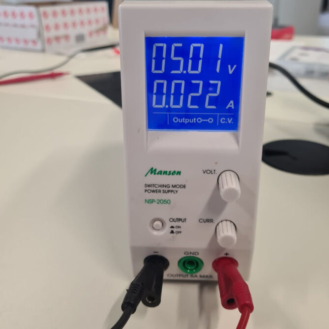
The setup for this is easy. Firstly, the bench power supply is turned on and then the voltage is regulated to about 5.0 V. Next, the current limiter is increased by connecting the plus and minus and pressing the "Output" button of the bench power supply and adjusting the current shown on the display with a turning know. Here, we set a value of about 0.2 A. Then, after turning the output off again, the plus of the bench power supply was connected to the 5V pin of the Seeedstudion XIAO and the minus to the ground. Now, the output can be turned on again. With this, the bench power supply showed a voltage of 5.01 V and a current of 0.022 A. This equals a power consumption of about 0.11 W.
Using Two Multimeters
For measuring the power consumption with multimeter, the voltage and the current also must be captured. However, when measuring these, the aspect of the arrangement must be considered. For the voltage, the multimeter must be arranged in parallel with the microcontroller. For the current, the multimeter must be in series with the microcontroller. Therefore, using two multimeters at the same time is beneficial.
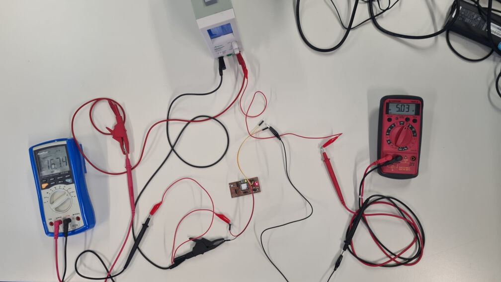
The setup is shown in the image. The power supply still powers the microcontroller. Additionally, two multimeters are connected to it, one in series for measuring the current (on the left) and one in parrallel for measureing the voltage (on the right). Here, the current is shown to be 16.74 mA and 5.03 V. This equals a power of approximately 0.08 W.
Blink Example
Commonly, an oscilloscope is used to measure (or even generate) waveforms as it allows a relatively high time-resolution, contrary to multimeters and bench power supplies. However, they are therefore also relatively expensive.
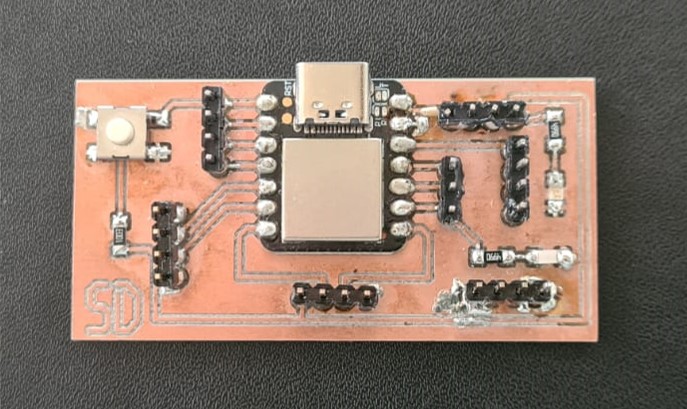
The first test with the oscilloscope for measuring the change of voltage included the measurement of the voltage for a blinking LED. Therefore, we used the PCB from Electronics Production (week 04) of Sophia Döring.
We used a simple blinking program in the Arduino IDE to get the built in LED to blink.
    const int ledPin =  8;// the number of the LED pin

    // the setup function runs once when you press reset or power the board
    void setup() {
        // initialize digital pin LED_BUILTIN as an output.
        pinMode(ledPin, OUTPUT);
    }

    // the loop function runs over and over again forever
    void loop() {
        digitalWrite(ledPin, HIGH);   // turn the LED on (HIGH is the voltage level)
        delay(1000);                       // wait for a second
        digitalWrite(ledPin, LOW);    // turn the LED off by making the voltage LOW
        delay(1000);                       // wait for a second
    }
To measure the voltage of the blinking pin, we attached the two end of one input of the oscilloscope to the according pin and the ground. While the oscilloscope was in the "running" state, it showed the high and low voltage that is alternating on the display as a horizontal line jumps up and down. By turning a certain know, the x-axis can be scaled such that the high and low phases were visible simultaneously.
It is also possible to measure certain parameters with the oscilloscope. In this case, we measured the amplitude which was found to be exactly 3.3V which is in accordance to the operating voltage of the microconroller.
Observing Pulse Width Modulation
Pulse Width Modulation (PWM) is a technique where a power source is rapidly switched on and off at varying intervals. The width of the on-time pulses can be adjusted, allowing control over the average power delivered to a device. It's commonly used in applications like motor speed control and LED dimming for its efficient and precise power regulation capabilities.
    const int PWMpin = 2;
    void setup() {
        pinMode(PWMpin, OUTPUT);
    }

    void loop() {
        analogWrite(PWMpin, 200);
    }
When measuring the voltage of that pin the multimeter showed a value of 2.6 V. We then measured the voltage with the oscilloscope to see PWM of the pin.
There are various parameters that can be measured. Here, we measured the amplitude which was 3.3
V. The frequency was 732.60 Hz and
the duty cycle was 78.13%. The latter matched the specified duty cycle quite well. The
analogWrite function in the
code above set the PWM duty cycle to 200 of 255 which is 78.43 %. With an amplitude of 3.3 V,
this averages to a voltage of
2.6 V which is the voltage we measured with the multimeter.
