SAMD11C Chip Programming
I used the Quentorres RP2040 Board that I made during Week 4 to flash the initial firmware to the SAMD11C chip. I went through multiple iterations of a SAMD11C board before settling on the board I would use. After flashing the firmware to allow the chip to be recognized as a SAMD11C chip by my laptop's USB port and the Arduino IDE, I wrote a simple LED blinking program to test the board. I then wrote a bare metal program and sent that to the chip.
Board Selection
Originally, I wanted to use a SAMDino board as my target board to program the SAMD11C. However, this board was not the final target board that I actually programmed. Due to a rough milling job and questionable soldering, I would end up abandoning this board in favor of the Hello D11C board. The Hello D11C board is a simpler board and also does not require the use of a connector, which is another part that the SAMDino requires that could have issues. The final board I used was the Hello D11C Board.
Work Distributions
We worked in small groups for this assignment. My group consisted of myself and Alana Duffy.
| People | Description |
| Richard | Documentation |
| Richard | SAMDino Board Milling |
| Richard | Hello D11C Board Milling |
| Richard | Hello SWD 10-4 Pin Connector Milling |
| Richard | Hello D11C Board & SAMDino Board Programming |
| Richard | RP2040 Programmer Setup |
| Richard | Flashing Firmware with EDBG |
| Richard | Bare Metal Programming |
| Alana | SAMDino Board Soldering |
| Alana | Hello D11C Board Soldering |
SAMDino
I initially decided to create a SAMDino board for the SAMD11C chip. I got the PNG from the SAMDino's website, which I then converted into a millable file.
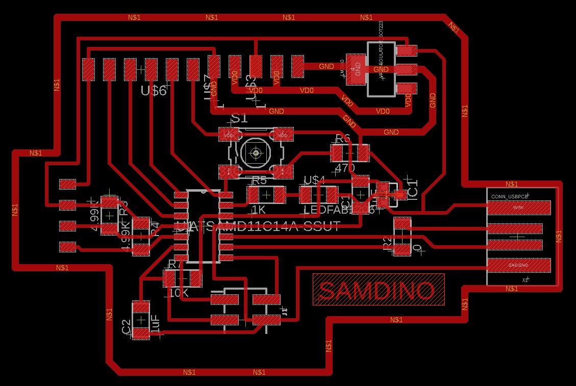
I then opened the NC file in Bantam, and milled the job. The milling job was pretty rough, which I found out afterwards was because I happened to choose a bit that was slightly chipped on the end. I only realized this when checking over the health of our bits with my instructor, Mr Dubick.
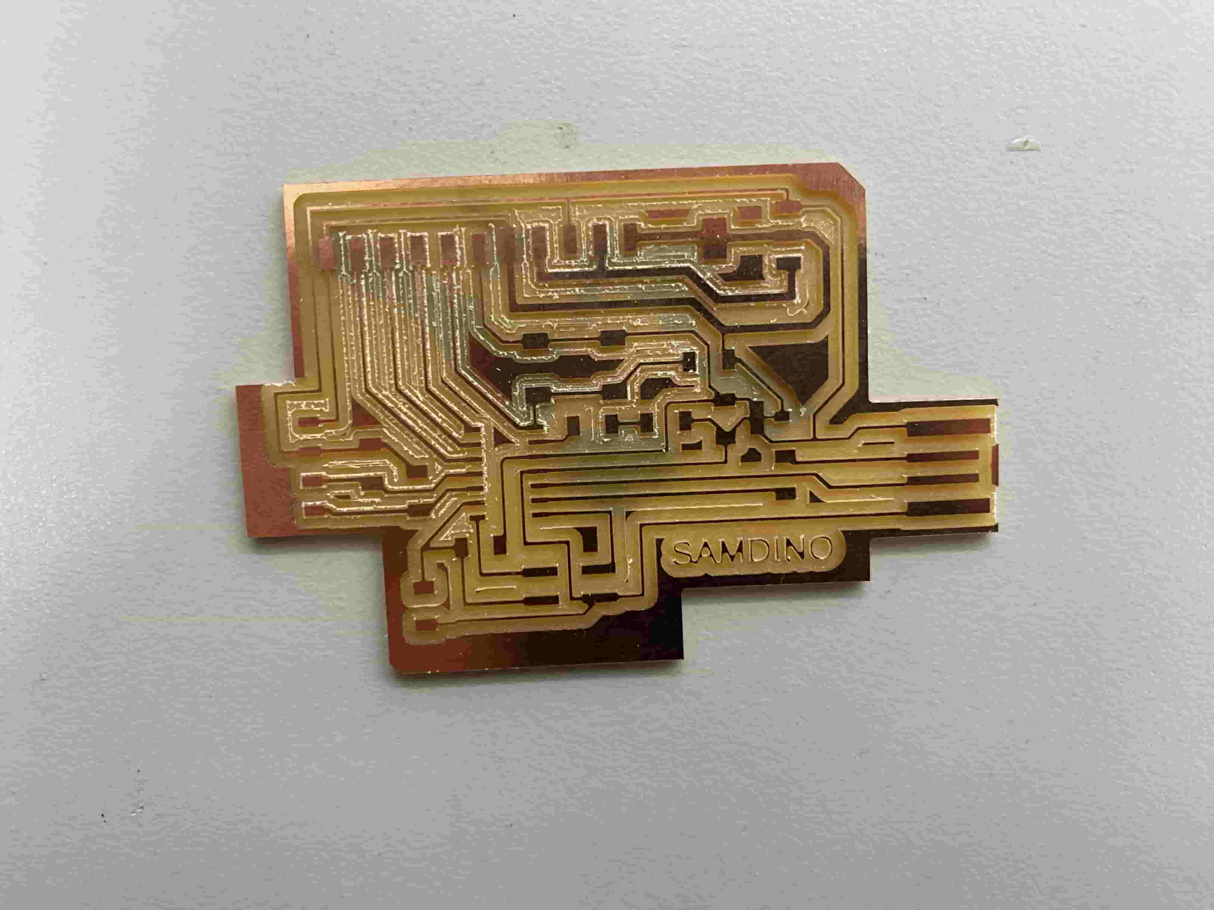
I then started preparing the programming as my partner, Alana Duffy, began to solder the SAMDino board.
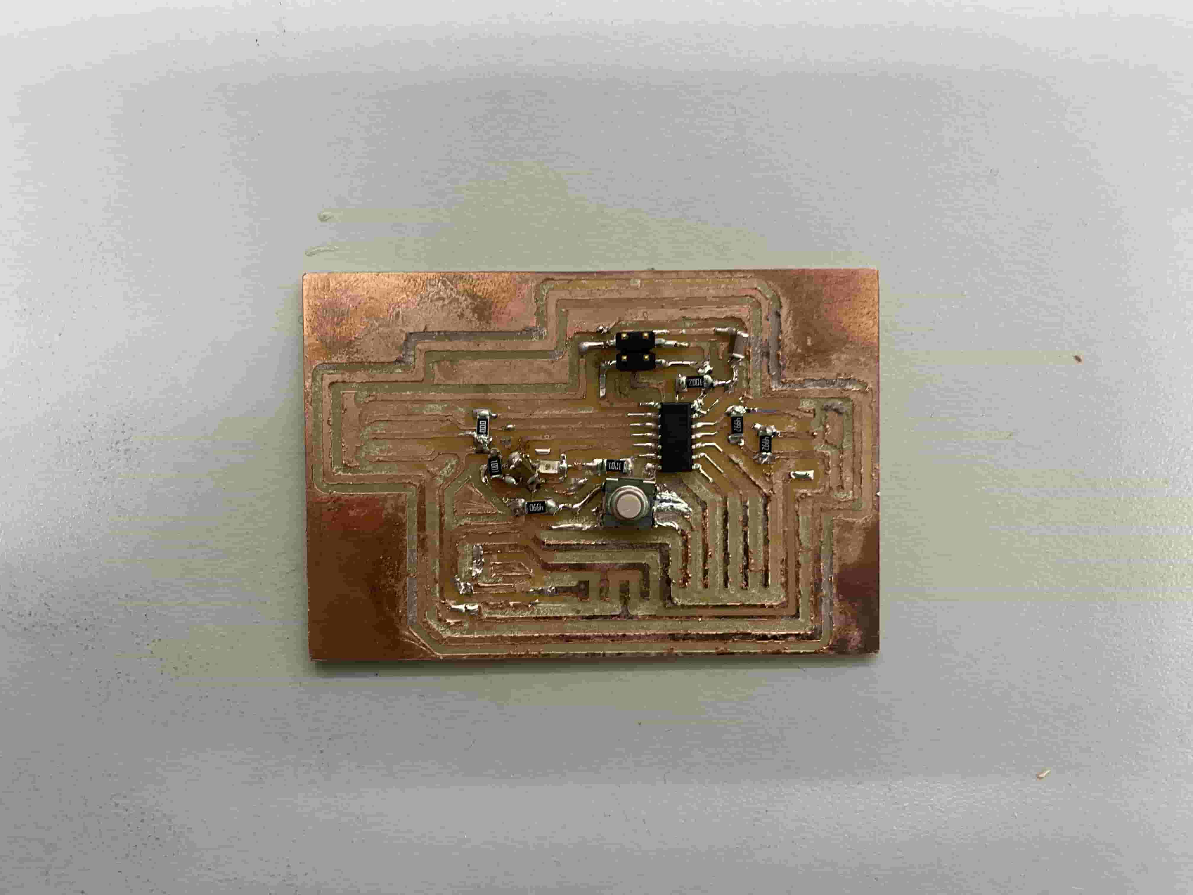
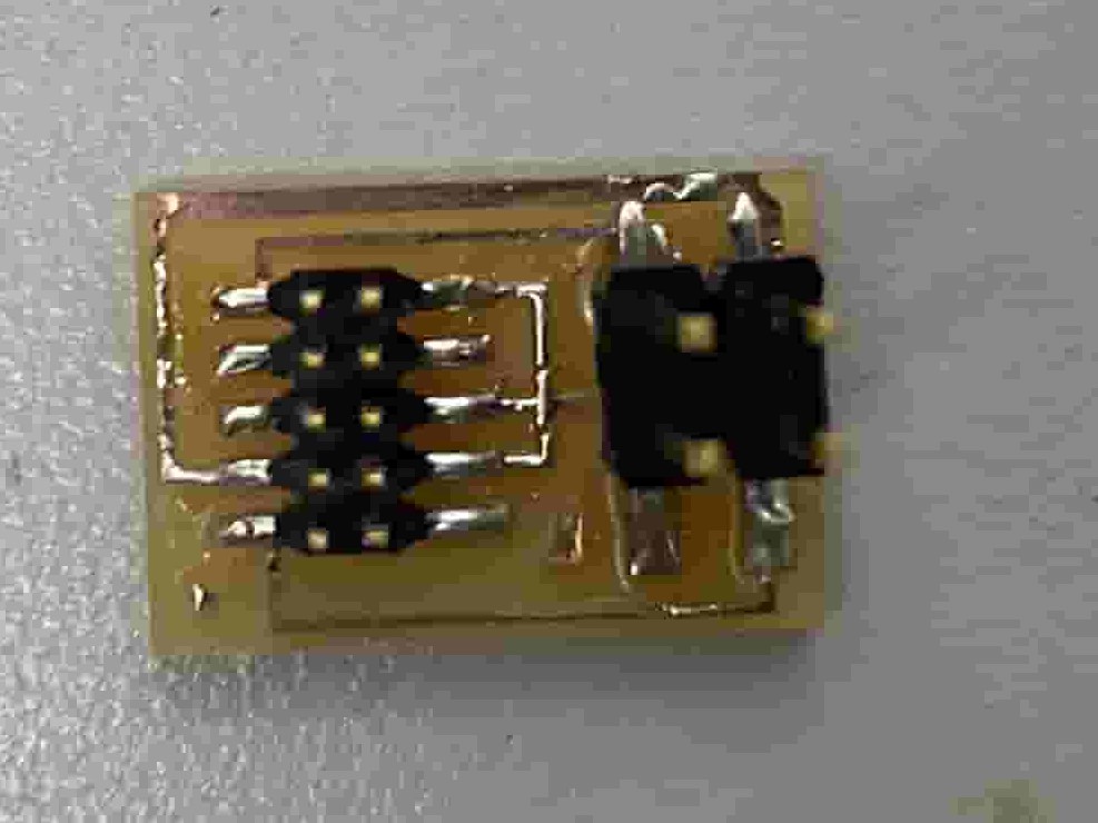
To be able to program the chip from the RP2040, we needed to design a connector that would adapt from a 2x5 pin cable to a 2x2. The RP2040 outputs from 2x5 pins but the SAMDino board takes a 2x2 pin input. I first downloaded the PNG of the schematic from the Fab Academy Schedule website.
I sent the schematic to Bantam Tools and ran the milling job. I milled two connector boards as I was going to give one of the boards to another group that was also dealing with the SAMD11C chip.
Alana then soldered the components.
I then took a careful look at the schematic of both the connector board and the SAMDino board to ensure that I wired the GND, RST, D10, and CLK pins to their respective corresponding pins on each board.
When I tried to program the board however, I encountered a multitude of errors. After around 5 hours of debugging, I ended up changing the SAMD11C board from the SAMDino to the Hello Board as it was a lot simpler.
SAMD11C Hello Board
After deciding to switch to the Hello Board, I first downloaded the PNG of the schematic from the Fab Academy schedule.
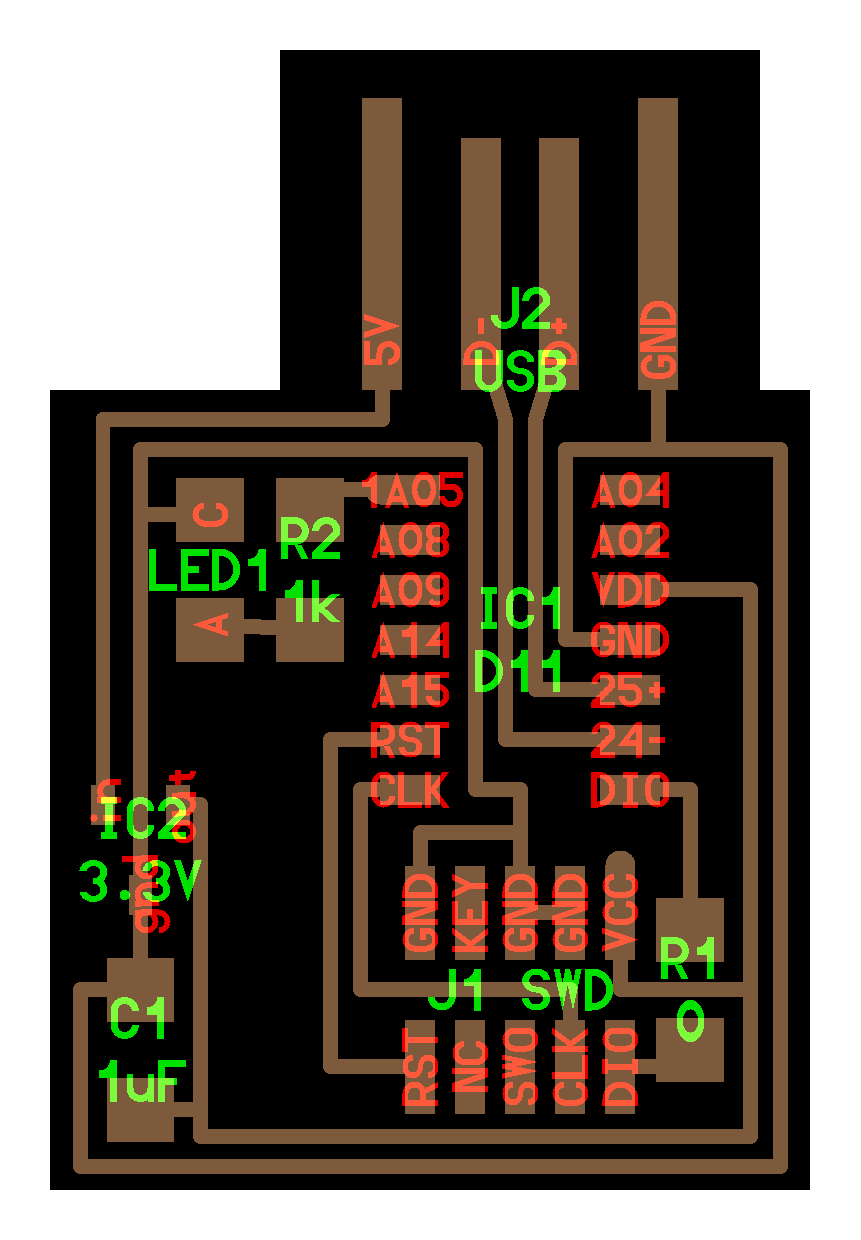
I then turned the PNG into a NC millable file and sent it to Bantam. I milled the board using a 1/32" bit and a 1/64" bit.
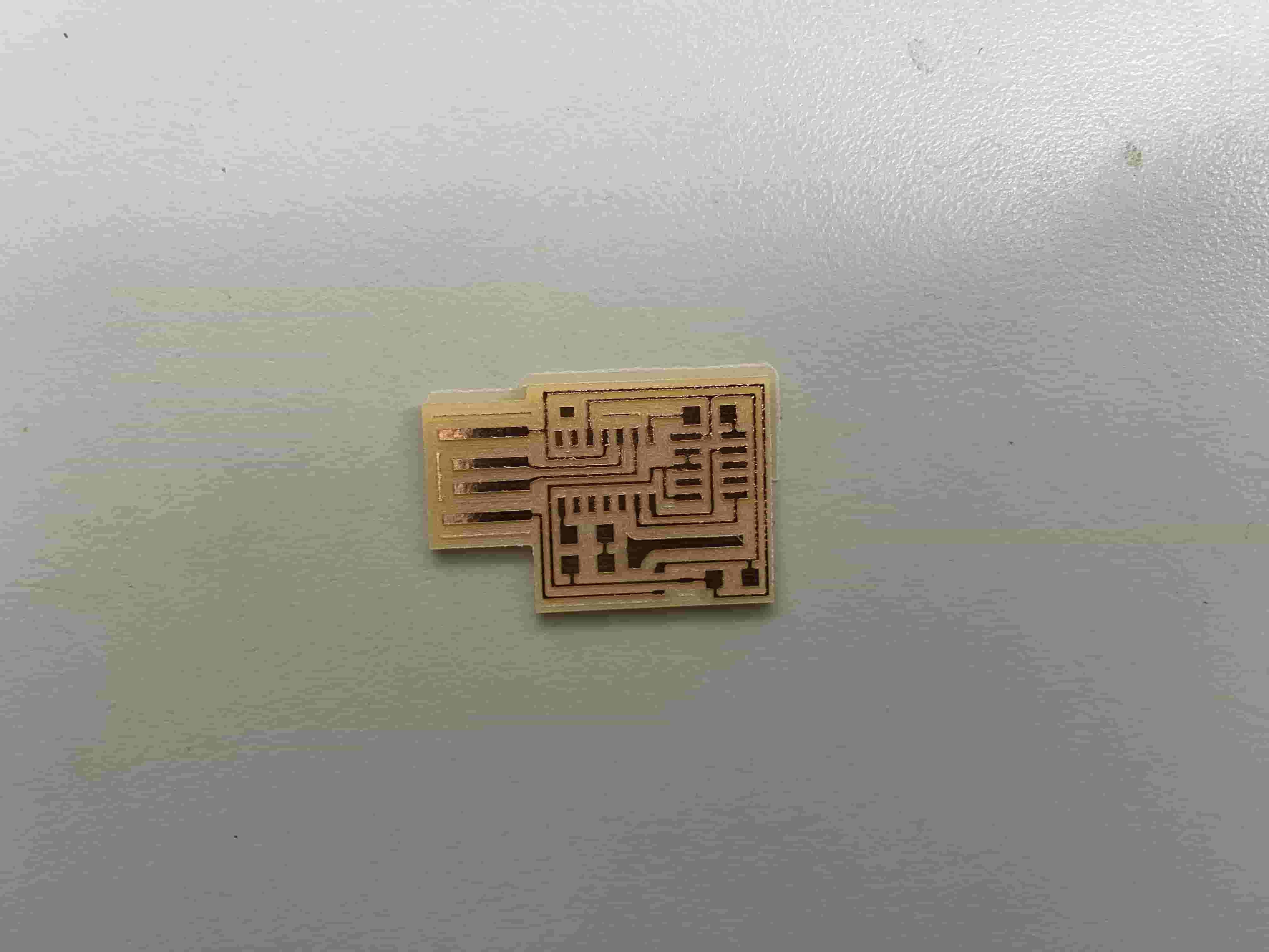
Alana soldered as usual.
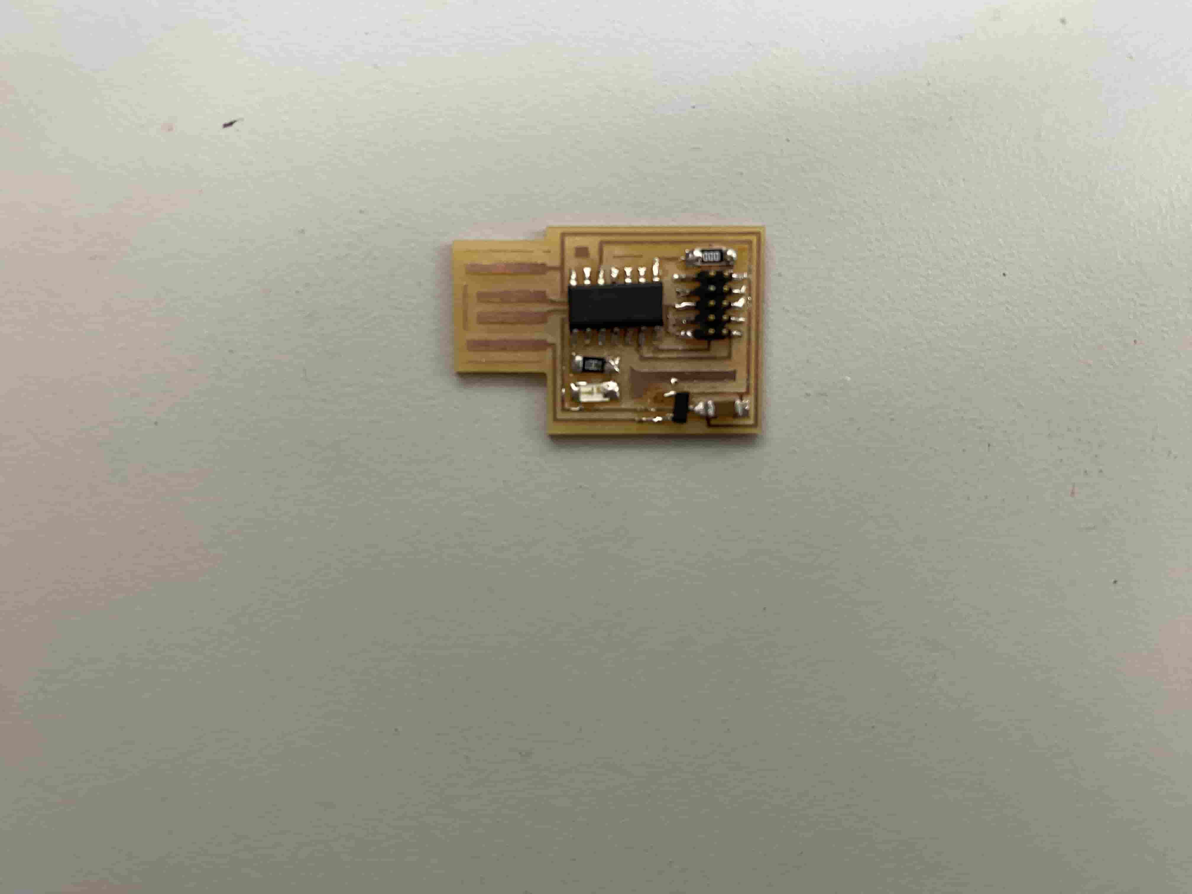
The board is now ready for programming!
Flashing Firmware
Debugger
To turn the RP2040 into a debugger, I uploaded the free_dap_rp2040.uf2 file to the RP2040, which I downloaded from the Fab Academy schedule and can also be found under my files for this week. To upload the file, I entered bootloading mode on the RP2040 by holding down the B button and clicking R. After doing that, the RP2040's storage appeared in Windows Explorer on my computer, where I uploaded the free_dap_rp2040.uf2 file.
EDBG
N.B.: When running the EDBG command, ensure that you call upon the executable using .\edbg instead of edbg as windows forces you to run untrusted commands as a executable
I first downloaded the latest Windows version of EDBG from the binary releases found here. EDBG, the Atmel Embedded Debugger, allows debugging of a target chip and flashing of firmware without the need of a specialized debugger. I then installed the sam ba Generic D11C14A SAMD11C14A bin file from this Github repo. This binary file is the basic level firmware that I will flash onto the target SAMD11C chip via the RP2040, which will allow the SAMD11C chip to be recognized by my computer's USB ports and be programmed directly via Arduino IDE.
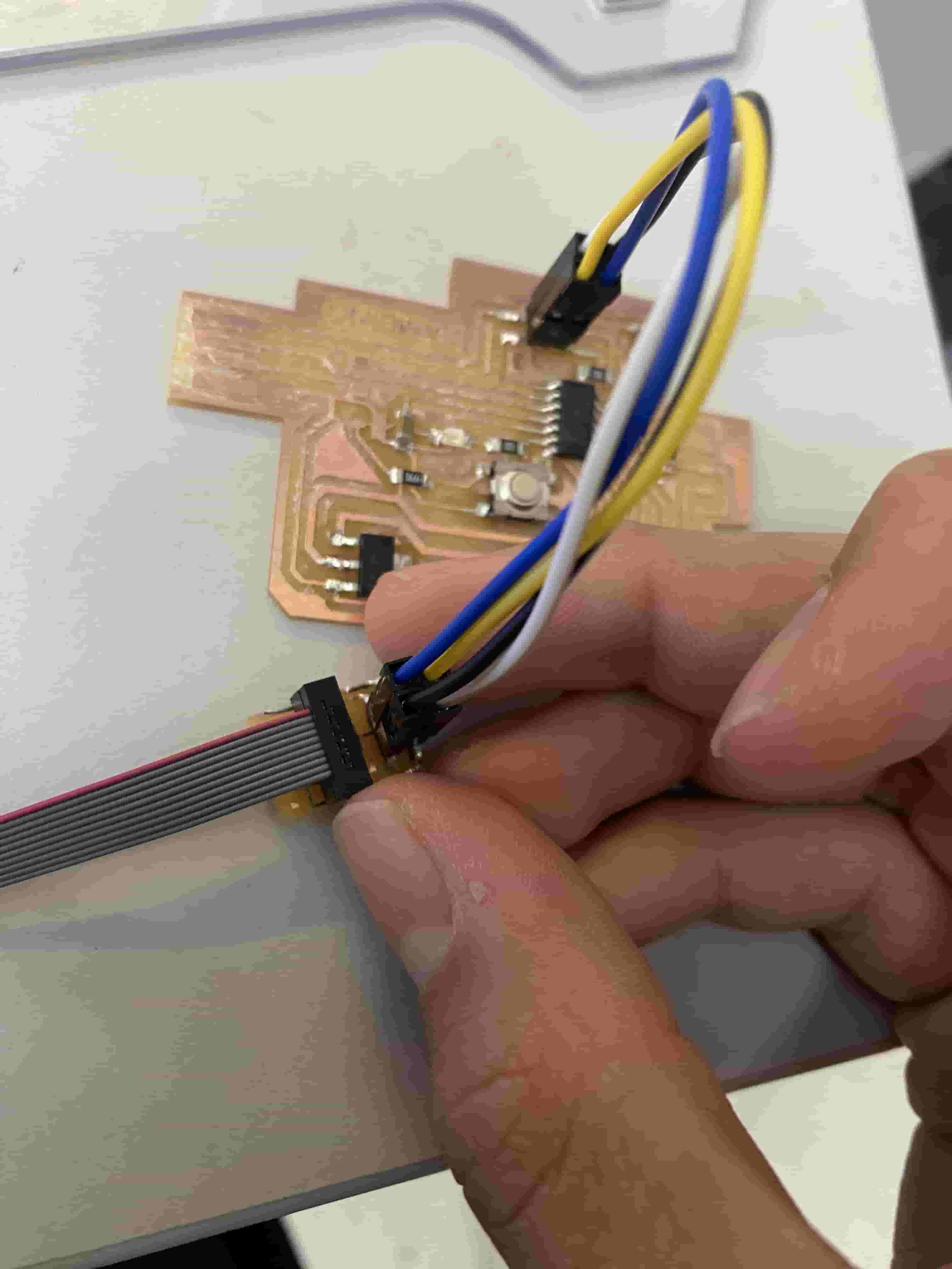
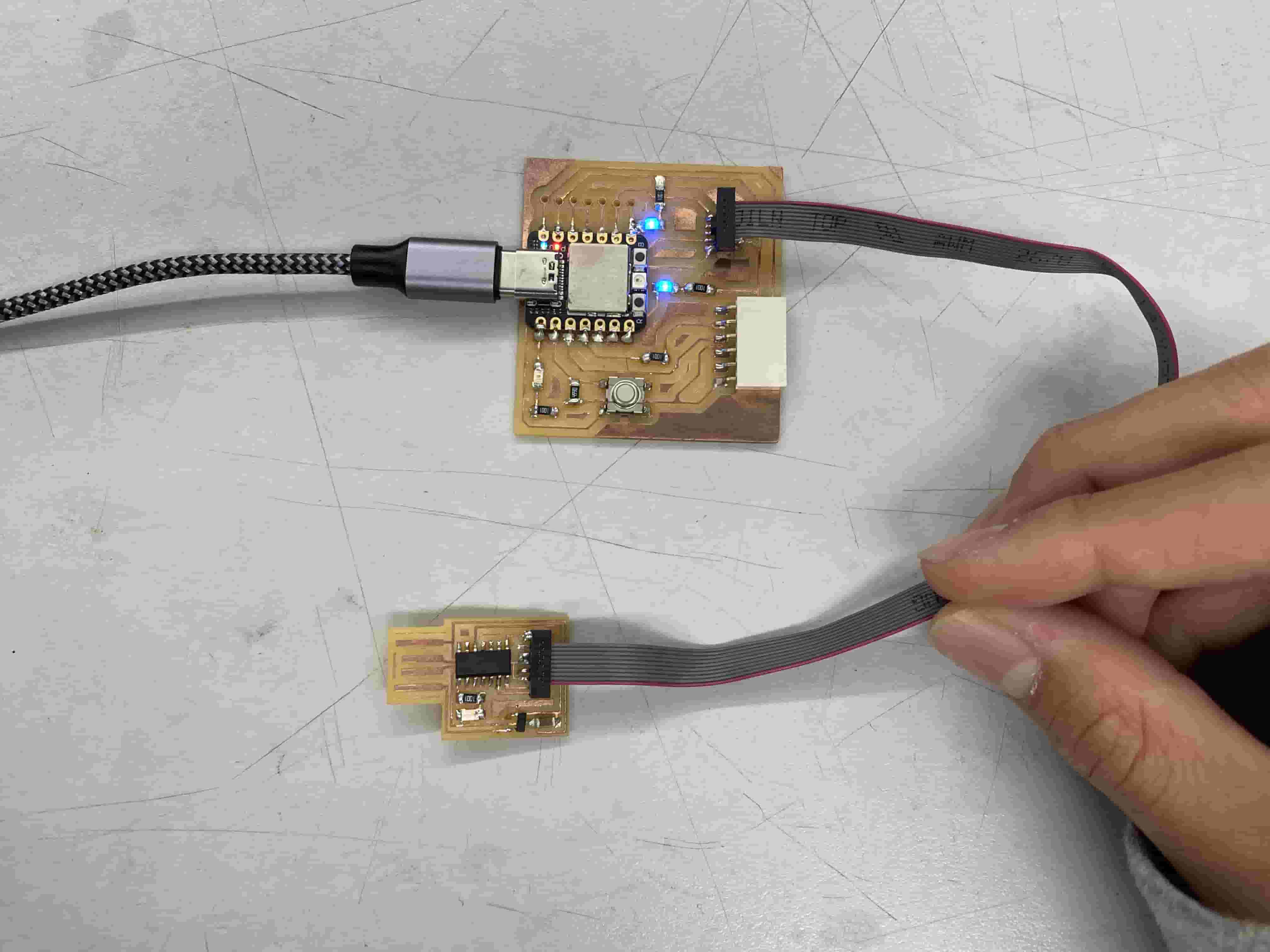
To setup the hardware, I used a 2x5 pin connector cable to connect the pin headers on the SAMD11C Hello Board to those on the Quentorres RP2040 Board.
I ensured that the hardware was sound by checking for connected debuggers using EDBG in command prompt.
PS C:\EDBG> .\edbg-windows-r61.exe -l
Attached debuggers:
  0: D1C428E8 - Alex Taradov Combined VCP and CMSIS-DAP Adapter (12)
This code calls upon the EDBG executable to print out any attached debuggers that it can detect. It is able to detect the RP2040 that is plugged in via USB cable, a positive sign.
To use EDBG, I first had to put my EDBG executable file was in the same directory of the sam_ba_Generic_D11C14A_SAMD11C14A.bin file. I did this by creating a "EDBG" folder under my root C:\ directory, and pasted I then opened a command prompt terminal window and flashed the bin file.
PS C:\EDBG> .\edbg-windows-r61.exe -b -p -v -e -t samd11 -f .\sam_ba_Generic_D11C14A_SAMD11C14A.bin
Debugger: Alex Taradov Generic CMSIS-DAP Adapter D1C428E8 2.0.0 (SJ)
Clock frequency: 16.0 MHz
Target: SAM D11C14A (Rev B)
Erasing... done.
Programming.... done.
Verification.... done.
This command calls upon the EDBG executable file to:
- Print the entire output message in the terminal (-b)
- Program the chip (-p)
- Verify that the program has been pushed to the chip's internal memory (-v)
- Erase the previous memory contents of the chip before programming (-e)
- Program a SAMD11 type board specifically (-t samd11)
- Program the chip with the sam_ba_Generic_D11C14A_SAMD11C14A.bin file (-f .\sam_ba_Generic_D11C14A_SAMD11C14A.bin)
The flashing process worked on my first attempt, but I noticed a lot of my peers were faced with the Error: invalid response during transfer (count = 0/1, status = 0) error message. Holding down both sides of the 2x5 pin connector cable (especially the side connecting to the Hello SAMD11C board) seemed to do the trick and allow for successful flashing. The fact that a large amount of my peers faced this exact same error and solution leads me to believe that it is not a simple soldering error, but rather a systemic issue with either the board or the pack of 2x5 connector cables that we ordered.
Regardless, the basic firmware is now in place on the board. Arduino IDE will now recognize it when plugged in to the USB port and I can begin coding!
Coding
N.B.: In the many hours that I spent attempting and researching, I did not come across a way to blink the LED through the RP2040. I could only blink the LED via a direct USB connection and code upload. The only thing that I was able to do through the RP2040 was flashing the initial bin file.
As Arduino IDE does not naturally recognize the SAMD11C board, I had to import an external library. I added the following URLs to my Arduino IDE Additional Boards Manager (File -> Preferences -> Additional Boards Manager URLs).
https://raw.githubusercontent.com/qbolsee/ArduinoCore-fab-sam/master/json/package_Fab_SAM_index.json
https://www.mattairtech.com/software/arduino/package_MattairTech_index.json
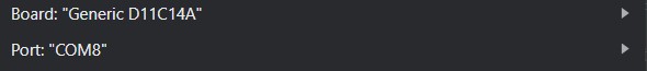
I then downloaded the megaTinyCore board library from the Boards Manager. After it finished downloading, I was able to select the SAMD11C board.
I wrote the following simple code to blink the LED on the board.
void setup() {
  pinMode(5, OUTPUT);
}

void loop() {
  digitalWrite(5, HIGH);
  delay(1000);
  digitalWrite(5, LOW);
  delay(1000);
}
The code upload was successful!
Sketch uses 9760 bytes (79%) of program storage space. Maximum is 12288 bytes.
Atmel SMART device 0x10030006 found
Device       : ATSAMD11C14A
Chip ID      : 10030006
Version      : v2.0 Nov 22 2017 12:56:25
Address      : 4096
Pages        : 192
Page Size    : 64 bytes
Total Size   : 12KB
Planes       : 1
Lock Regions : 16
Locked       : none
Security     : false
Boot Flash   : true
BOD          : true
BOR          : true
Erase flash
done in 2.161 seconds

Write 10112 bytes to flash (158 pages)

[                              ] 0% (0/158 pages)
[==                            ] 9% (15/158 pages)
[=====                         ] 18% (30/158 pages)
[========                      ] 28% (45/158 pages)
[===========                   ] 37% (60/158 pages)
[==============                ] 47% (75/158 pages)
[=================             ] 56% (90/158 pages)
[===================           ] 66% (105/158 pages)
[======================        ] 75% (120/158 pages)
[=========================     ] 85% (135/158 pages)
[============================  ] 94% (150/158 pages)
[==============================] 100% (158/158 pages)
done in 24.355 seconds

Verify 10112 bytes of flash

[                              ] 0% (0/158 pages)
[==                            ] 9% (15/158 pages)
[=====                         ] 18% (30/158 pages)
[========                      ] 28% (45/158 pages)
[===========                   ] 37% (60/158 pages)
[==============                ] 47% (75/158 pages)
[=================             ] 56% (90/158 pages)
[===================           ] 66% (105/158 pages)
[======================        ] 75% (120/158 pages)
[=========================     ] 85% (135/158 pages)
[============================  ] 94% (150/158 pages)
[==============================] 100% (158/158 pages)
Verify successful
done in 0.083 seconds
CPU reset.
Here is a video of my blinking LED.