CAM in Aspire
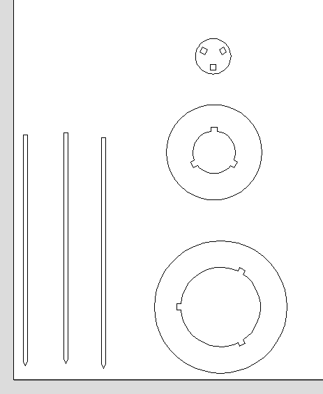
I first opened up the DXF file that I exported from Fusion in Aspire. Here is the 2D view of the file after I slightly moved the design away from the edges, so that the actual cut would have some leeway on the board edges.
After I was satisfied with the placement of my design, I started the CAM process and designing my toolpaths. I did this via the Toolpath menu of Aspire on the right hand side of the GUI. Here are the settings of the toolpath I created for the legs of my shelf.
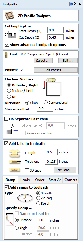
The cutting depth of 0.45 inches means that the machine will cut 0.45 inches deep along the toolpath. I chose this value because my wood board is 0.45 inches thick. Our instructor advised us that although this wood was sold as being half an inch thick, for CAM purposes specifically, we should independently verify the actual thickness of the wood.
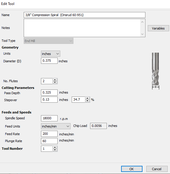
The 3/8" Compression Spiral tool was the bit that our Shopbot machine uses. My instructor provided the information for the tool so that we were able to modify the specifications of the tool on Aspire.
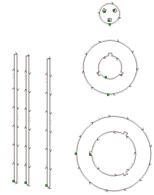
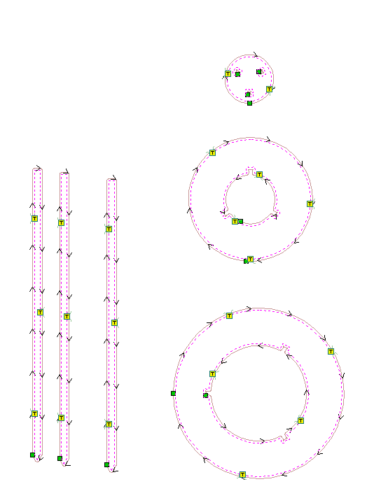
For the legs toolpath specifically, I chose the outside cutting setting. This means that the machine would cut on the outside of the component, meaning that the remaining material would be the exact size that I designed the leg. I also chose the outside setting for cutting the outside of my shelves, because I wanted to maintain the original dimensions. However, when I was cutting the internal cutouts of each shelf rack, I chose inside cutting because cutting on the inside in the middle of a shelf would create a hole to the same size that I intended. I was a little confused on why I would ever use the "On" cutting setting, and my instructors told me that I would only ever use this setting if the design was specifically made to be cut on directly. The following is a render of my toolpaths in the 2D Aspire menu.
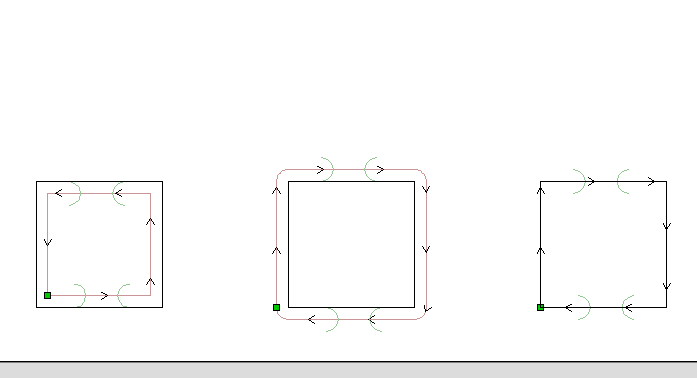
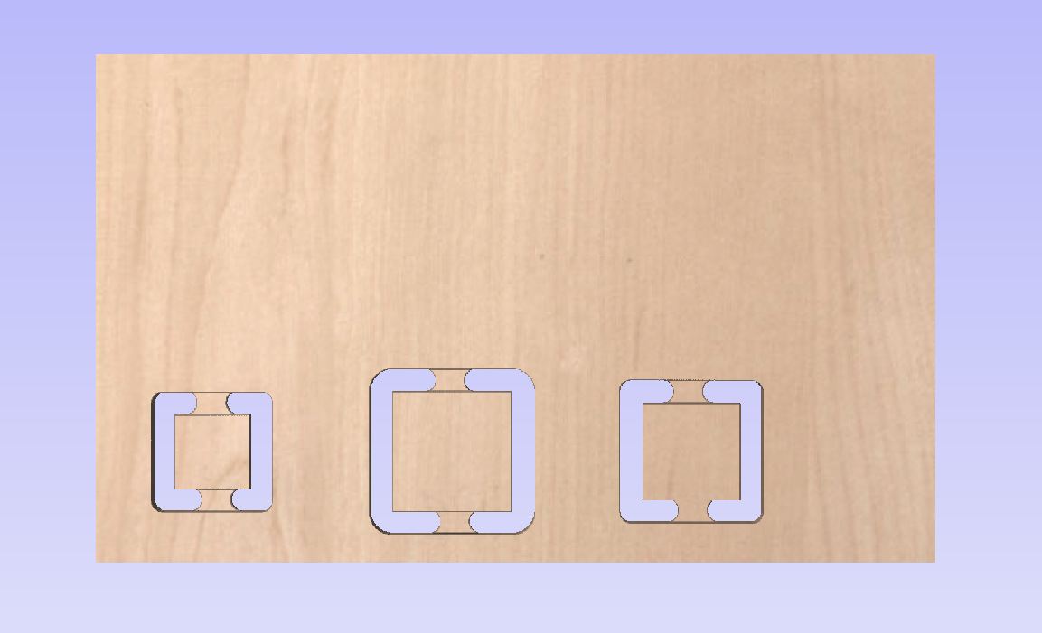
To demonstrate the importance of choosing the correct inside/outside/on toolpath setting, I created a simple design shown in the images below. All three squares are 2 inches by 2 inches, but they vary in whether the toolpath selection is inside, outside, or on the line.
 |
 |
Using the Edit Tabs button, I was able to manually select some spots that I wanted to add tabs on. Tabs are small bits of wood that are easily removed but hold the design to the rest of the board during cutting, so that the wood cutouts do not fly off and become a safety hazard immediately after they are cut out. The tabs are visible in the 2D render as a small T icon and in the 3D render.
 |
 |
When our instructor was giving us a high-level overview of CNCing, he mentioned that we should include ramping in our cut so that the tool would not experience a lot of stress when initially drilling into the material. As such, I checked the ramp generation box and accepted the default generation specifications.
After I created individual toolpaths for the cutout of the legs, the outer cutouts of the shelves, and the inner cuts for the shelves, I then exported the file as a .sbp file for the ShopBot software.
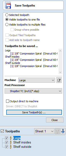
I exported all toolpaths as one file so that I could run the entire cut in one go, and selected the ShopBot TC as the post processor so that the file would be saved as a .sbp file that the ShopBot Software can use. I selected all 3 of my toolpaths to export in the checklist menu at the bottom. I then saved the file and prepared to cut.