Custom PCB Testing
Soldering
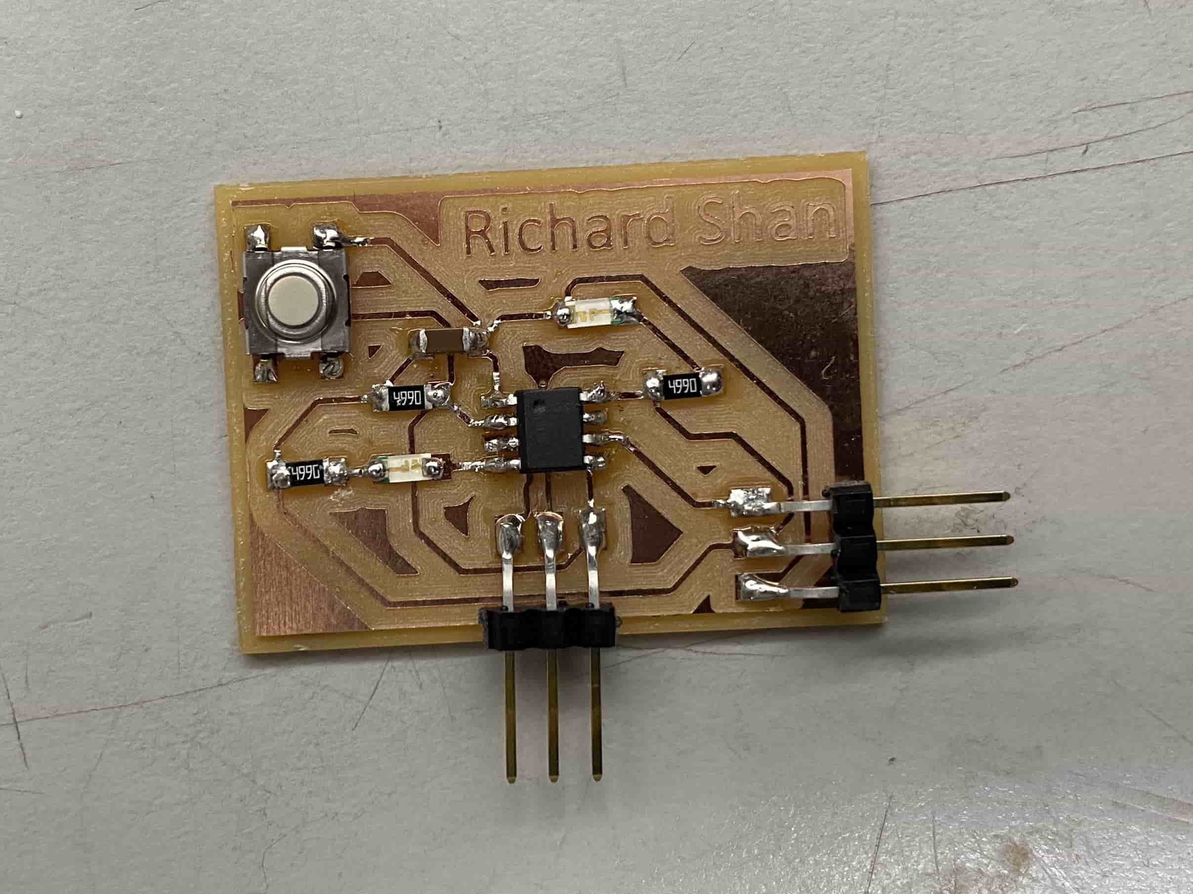
After I milled the board, I soldered on all of my components, using my KiCAD design to help guide me. The soldering went pretty smoothly with the exception of the ATTiny412 chip, which I soldered backwards. This was fixed by pulling the chip up from the board with tweezers under a heat gun. I later realized that the small "dot" on the ATTiny chip had a corresponding indication on the schematic.
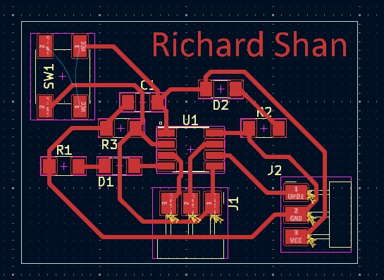
Here is my board after I soldered on 2 connecting pin headers, 3 5k ohm resistors, 1 ATTiny412 chip, 2 blue LEDs, 1 tactile button switch, and 1 970 nF capacitor.
Because I wanted to program this board through the Quentorres, I needed a connector that would adapt from the Quentorres' 6 pin output to 3 pins. I originally borrowed a connector from Evan Park, but because I wanted to continue programming at home, I decided to make my own.
I first downloaded the board file from the Fab Academy schedule page.
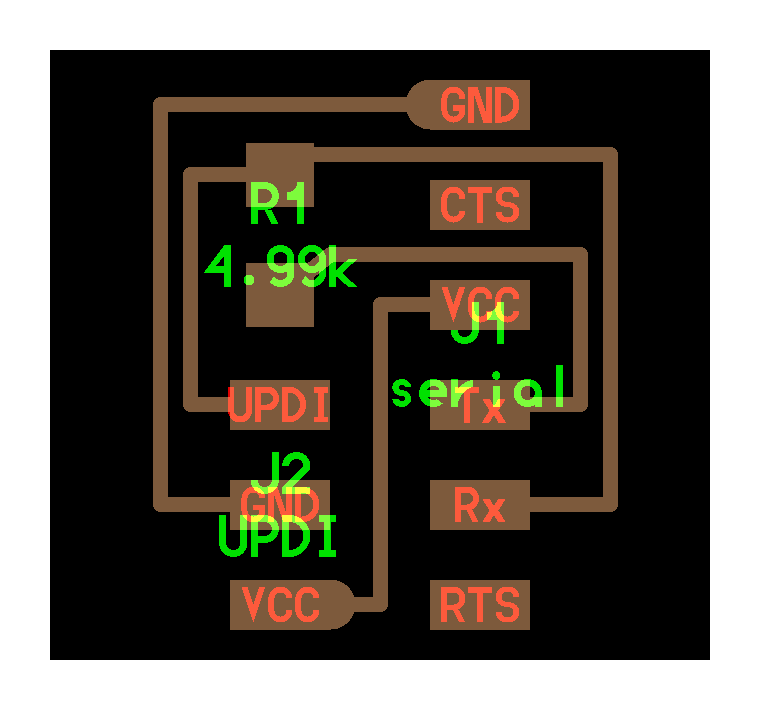
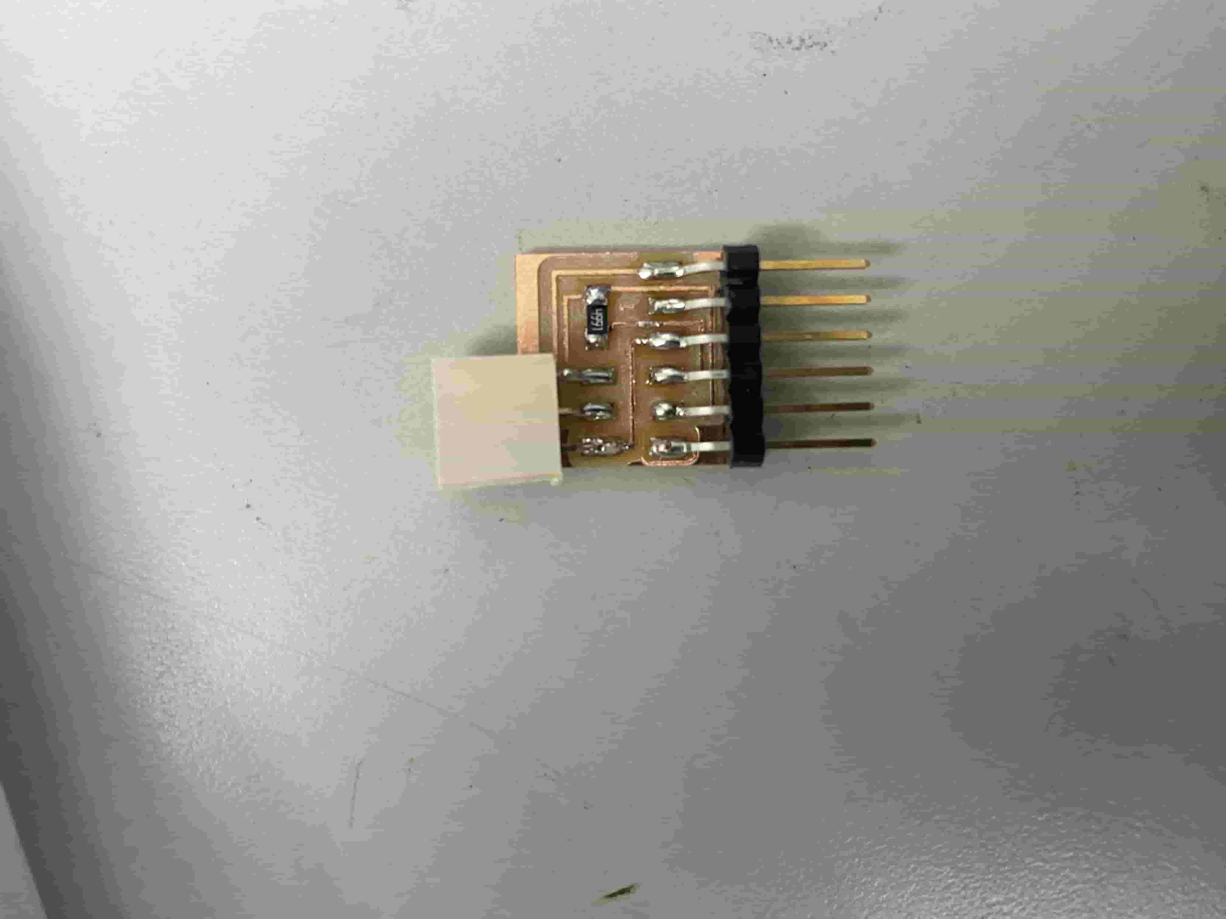
I then milled the board and soldered on a 6 pin header, and 3 pin connector, and a 5k ohm resistor. Here is the finished connector.
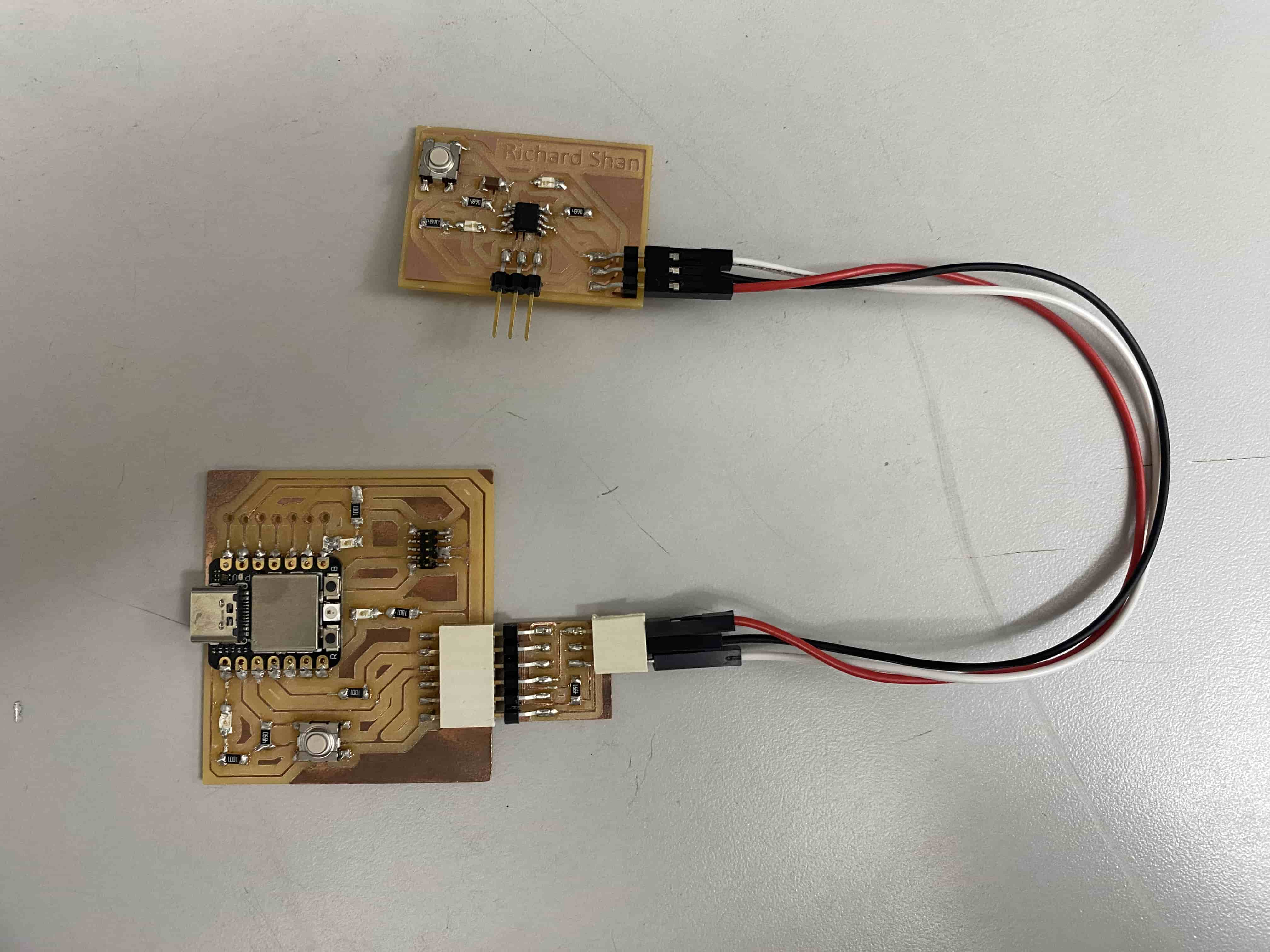
Here is my board connected to the RP2040 board through the connector. The connector adapts the 6 pin output of the Quentorres board into the only three inputs that my board is sending to the ATTiny412: UPDI, GND, and VCC.
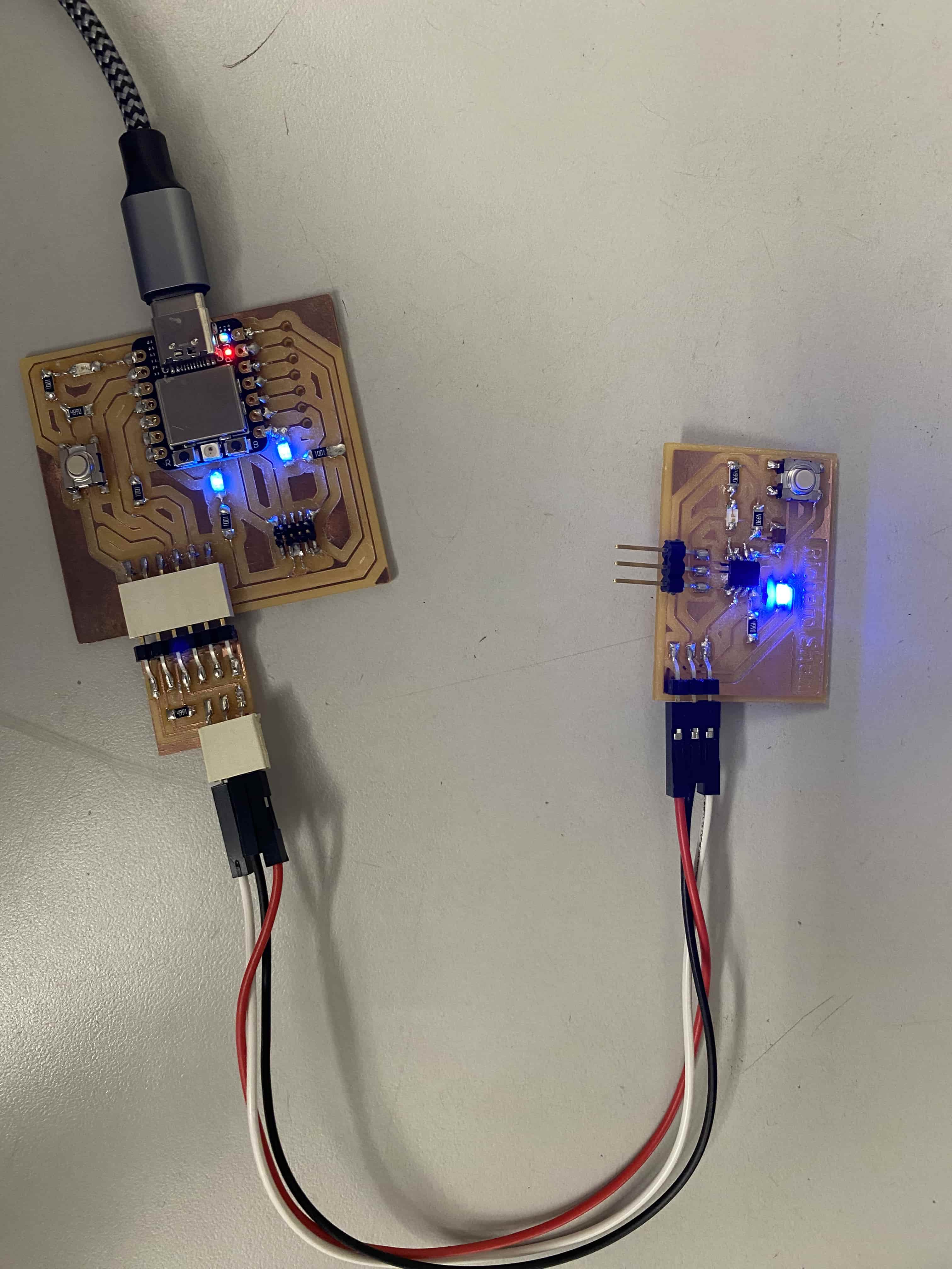
I then plugged in both boards to power. The power indication LED turned on!
Time to program.