Final Project Brainstorming
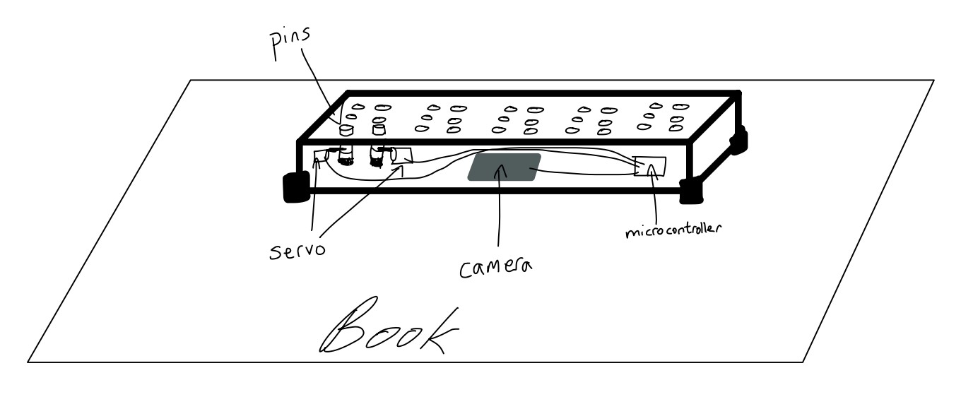
My idea was to design a text to braille converter, which a blind person could use by moving the device over a page of text to convert it into braille. The braille translation of the english text would then be represented via a series of up/down pins which the user could use to interpret the information. The device was to be a rectangular box that would use an internal camera to interpret and OCR text, which could then be translated into braille and displayed via a series of servo motors pushing up metal rods on the top of the box. The pins would be in groups of six, each group representing a single braille character.
However, I talked to Stuart Christhilf who had thought of a similar mechanism for his initial final project. He originally planned to create a dynamic clock to display the time using blocks of wood that acould be pushed out or pulled back via servos. However, when building his project, he realized that fitting so many servos into such a small space was completely unfeasible and warned me from doing the same. My initial design is shown in the following image:
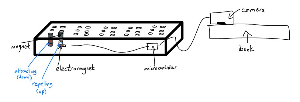
I then decided to use electromagnets for my pins, instead of a servo. The pins themselves would be a small magnetic rod sitting on top of an electromagnet. The small electromagnet could be powered on and off via a microcontroller. When the electromagnet was off, the pin would simply rest on top of the electromagnet, and the pin would be flush against the top of the board, forming the down position of the pin. If the pin needed to pop up, the microcontroller would power the electromagnet which would then emit a repelling magnetic charge. That magnetic force would then repel the pin slightly upwards, forming the up position of the pin. To represent a braille character, the microcontroller would push the specific pins into the up position that together would form the 6-dot pattern of the character.
I also decided to move the camera out of the box. That would allow for more simple wiring and internal organization of the box, and allow the operator to more easily use the device. Moving the camera out means that the user would only need to move a small camera container across the page of text, instead of dragging the entire device. Here is my modified design:
I then mapped out relevant weeks of Fab Academy:
- Week 2: CAD - Designing the 3D printed structure
- Week 4: Embedded Programming - Programming microcontrollers
- Week 5: 3D Printing - Printing custom components
- Week 6: Electronics - PCB design
- Week 7: CNC - Creating a magnet, board making, internal wiring organization
- Week 8: Electronics Production - Hooking up microcontrollers with magnets
- Week 9: Output Devices - Board work
- Week 11: Input Devices - Camera OCR work and hooking up to microcontroller
- Week 12: Molding - Alternate option to mold the box
- Week 13: Networking - Use a online libary/package for braille conversion
- Week 14: Interfacing - Use Processing to flesh out the internal connections
- Week 15: Wildcard - Electromagnets experimentation