Wireless Camera Image Transmission
Assignment
This week, I was assigned to connect wireless nodes with network addresses and use a local input device.
I decided to use this week's assignment to further develop my final project. I thus decided to develop two programs. One program would be uploaded to the ESP32CAM, which listens and waits for a remote connection via its local IP address on a common WiFi network. The ESP32 will then take a picture when prompted by the remote connection then send the data of the image over Websocket HTTP to a receiving device. The second program is a python script running on a Raspberry Pi. This script initiates a Websocket connection to the IP of the ESP32CAM, and then receives the image, which is saved locally on the recipient device.
WebSocket Methodology
WebSocket connections are initiated through HTTP protocol, using an upgrade request from HTTP to WebSocket. This begins with a client sending a standard HTTP request that includes an "Upgrade: websocket" header and a "Connection: Upgrade" header to the server. The server then responds with an HTTP 101 status code, indicating that the protocol will change, thus establishing the WebSocket connection.
WebSocket, uses IP addresses to facilitate the initial connection before upgrading to the WebSocket protocol. Once the WebSocket connection is established, the IP addresses are used to maintain the connection over which data frames can be reliably transmitted back and forth.
Once the WebSocket connection is established, data is transmitted in framed messages through backend data transmission ports, where each frame consists of an opcode to indicate the type of data being transmitted (e.g., text, binary, continuation frame, or control frames like close, ping, or pong). This structure allows the WebSocket protocol to be extremely versatile and efficient in handling different types of data seamlessly. The frames are small and allow for very efficient data transmission.
ESP32CAM Board Programming
The following program is uploaded onto the ESP32 CAM Board through Arduino IDE. This program requires a lot of libraries and dependencies, which I individually downloaded from Github. For some reason, my Arduino IDE library loader wasn't working properly, so I searched online for any missing libraries and downloaded their .h files, and moved them to my project working directory. The entire project folder including the code and libraries can be downloaded under this week's file downloads. This program is based off of the CameraWebServer example program from ESP32.
#include "esp_camera.h"
#include "WiFi.h"
#include "WebSocketsServer.h"

#define CAMERA_MODEL_AI_THINKER // Has PSRAM
#include "camera_pins.h"

const char* ssid = "REDACTED";
const char* password = "REDACTED";

WebSocketsServer webSocket = WebSocketsServer(81);

void startCameraServer();
void setupLedFlash(int pin);
void onWebSocketEvent(uint8_t client_num, WStype_t type, uint8_t *payload, size_t length);

void setup() {
  pinMode(2, OUTPUT);
  Serial.begin(9600);
  while (!Serial); // Wait for the serial connection to initialize
  Serial.setDebugOutput(true);
  Serial.println();

  camera_config_t config;
  config.ledc_channel = LEDC_CHANNEL_0;
  config.ledc_timer = LEDC_TIMER_0;
  config.pin_d0 = Y2_GPIO_NUM;
  config.pin_d1 = Y3_GPIO_NUM;
  config.pin_d2 = Y4_GPIO_NUM;
  config.pin_d3 = Y5_GPIO_NUM;
  config.pin_d4 = Y6_GPIO_NUM;
  config.pin_d5 = Y7_GPIO_NUM;
  config.pin_d6 = Y8_GPIO_NUM;
  config.pin_d7 = Y9_GPIO_NUM;
  config.pin_xclk = XCLK_GPIO_NUM;
  config.pin_pclk = PCLK_GPIO_NUM;
  config.pin_vsync = VSYNC_GPIO_NUM;
  config.pin_href = HREF_GPIO_NUM;
  config.pin_sscb_sda = SIOD_GPIO_NUM;
  config.pin_sscb_scl = SIOC_GPIO_NUM;
  config.pin_pwdn = PWDN_GPIO_NUM;
  config.pin_reset = RESET_GPIO_NUM;
  config.xclk_freq_hz = 20000000;
  config.frame_size = FRAMESIZE_UXGA;
  config.pixel_format = PIXFORMAT_JPEG;
  config.grab_mode = CAMERA_GRAB_WHEN_EMPTY;
  config.fb_location = CAMERA_FB_IN_PSRAM;
  config.jpeg_quality = 12;
  config.fb_count = 1;

  if (psramFound()) {
    config.jpeg_quality = 10;
    config.fb_count = 2;
    config.grab_mode = CAMERA_GRAB_LATEST;
  }

  esp_err_t err = esp_camera_init(&config);
  if (err != ESP_OK) {
    Serial.printf("Camera init failed with error 0x%x", err);
    return;
  }

  sensor_t *s = esp_camera_sensor_get();
  s->set_vflip(s, 1); // Flip it back
  s->set_brightness(s, 1); // Up the brightness just a bit
  s->set_saturation(s, -2); // Lower the saturation

#if defined(LED_GPIO_NUM)
  setupLedFlash(LED_GPIO_NUM);
#endif

  WiFi.begin(ssid, password);
  WiFi.setSleep(false);
  while (WiFi.status() != WL_CONNECTED) {
    delay(500);
    Serial.print(".");
  }

  Serial.println("");
  Serial.println("WiFi connected");
  webSocket.begin();
  webSocket.onEvent(onWebSocketEvent);
  startCameraServer();

  Serial.print("Camera Ready! Use 'http://");
  Serial.print(WiFi.localIP());
  Serial.println("' to connect");
}

void loop() {
  webSocket.loop();
}

void onWebSocketEvent(uint8_t client_num, WStype_t type, uint8_t *payload, size_t length) {
  switch (type) {
    case WStype_DISCONNECTED:
      Serial.printf("[%u] Disconnected!\n", client_num);
      break;
    case WStype_CONNECTED:
      {
        IPAddress ip = webSocket.remoteIP(client_num);
        Serial.printf("[%u] Connection from ", client_num);
        Serial.println(ip.toString());
      }
      break;
    case WStype_TEXT:
      if (strcmp((char *)payload, "capture") == 0) {
        camera_fb_t *fb = esp_camera_fb_get();
        if (!fb) {
          Serial.println("Camera capture failed");
        } else {
          webSocket.sendBIN(client_num, fb->buf, fb->len);
          esp_camera_fb_return(fb);
        }
      }
      break;
    case WStype_BIN:
      Serial.printf("[%u] Get binary length: %u\n", client_num, length);
      break;
  }
}

void setupLedFlash(int pin) {
  pinMode(pin, OUTPUT);
  digitalWrite(pin, LOW);
}
This program connects the ESP32CAM to a local WiFi network. It then sets up and initializes the camera, and sets up the local IP connection. It then continuously waits for a web socket connection. When a connection is created, it prints the IP address of the connecting device. If the device sends an input of "capture", the camera will take a picture and send it via the network web socket connection to the connecting Raspberry Pi.
Recipient Device Programming
This python program is ran on a computer, Raspberry Pi, or other similar device with storage and WiFi capabilities. This program acts as the trigger for the ESP32CAM to capture an image. Something interesting I noticed is that when running the standard CameraWebServer, there is a lot of lag and downtime with the camera. However, when querying for a single capture, there is low latency.
import websocket
import time

def on_message(ws, message):
    with open('received_image.jpg', 'wb') as f:
        f.write(message)
    print("Received image and saved.")

def on_error(ws, error):
    print("Error:", error)

def on_close(ws, close_status_code, close_msg):
    print("### closed ###")
    print("Close status code:", close_status_code)
    print("Close message:", close_msg)

def on_open(ws):
    def run(*args):
        time.sleep(1)
        ws.send("capture")
        time.sleep(1)
        ws.close()
    import threading
    threading.Thread(target=run).start()

if __name__ == "__main__":
    websocket.enableTrace(True)
    ws = websocket.WebSocketApp("ws://10.12.28.193:81",
                                on_message=on_message,
                                on_error=on_error,
                                on_close=on_close)
    ws.on_open = on_open
    ws.run_forever()
Aggregate
I created the following diagram to visualize how all of this week's constituent parts come together.
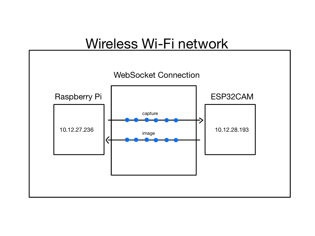
When running the ESP32CAM C++ program and then querying it for a capture, the following is logged in Serial:
WiFi connected
Camera Ready! Use 'http://10.12.28.193' to connect
[0] Connection from 10.12.27.236
[0] Disconnected!
The ESP32 first connects to WiFi then outputs its local address. When the Raspberry Pi connects to that local address, it prints a notification message and the address of the connecting device. Once the image is taken and transmitted, the Raspberry Pi disengages the connection.
The following output results from running the Python program to connect to the camera, command it to capture an image, and save the transmitted image.
--- request header ---
GET / HTTP/1.1
Upgrade: websocket
Host: 10.12.28.193:81
Origin: http://10.12.28.193:81
Sec-WebSocket-Key: W3XMXlqqNTcevz9IOa4JKQ==
Sec-WebSocket-Version: 13
Connection: Upgrade


-----------------------
--- response header ---
HTTP/1.1 101 Switching Protocols
Server: arduino-WebSocketsServer
Upgrade: websocket
Connection: Upgrade
Sec-WebSocket-Version: 13
Sec-WebSocket-Accept: BcYWmHH3lBtfcfsNo2eUGf/fGkg=
-----------------------
Websocket connected
++Rcv raw: b'\x89\x00'
++Rcv decoded: fin=1 opcode=9 data=b''
++Sent raw: b'\x8a\x80%J-\xf8'
++Sent decoded: fin=1 opcode=10 data=b''
++Sent raw: b'\x81\x87\x12\x9b\x05%q\xfauQg\xe9`'
++Sent decoded: fin=1 opcode=1 data=b'capture'
++Sent raw: b'\x88\x82\x93;\xe9W\x90\xd3'
++Sent decoded: fin=1 opcode=8 data=b'\x03\xe8'
++Rcv raw: [Image data removed for readability]
Received image and saved.
### closed ###
Close status code: None
Close message: None
I have removed the raw data of the image in the log message above both for security purposes and because the output is incredibly long. The received raw image data is similar to the example below, but a few hundred times longer.
Image Raw Data
b'\x82\x7f\x00\x00\x00\x00\x00\x01\x1a\x15\xff\xd8\xff\xe0\x00\x10JFIF\x00\x01\x01\x01\x00\x00\x00\x00\x00\x00\xff\xdb\x00C\x00\n\x07\x08\t\x08\x06\n\t\x08\t\x0b\x0b\n\x0c\x0f\x19\x10\x0f\x0e\x0e\x0f\x1f\x16\x17\x12\x19$ &&$ #"(-:1(+6+"#2D36;=@A@\'0GLF?K:?@>\xff\xdb\x00C\x01\x0b\x0b\x0b\x0f\r\x0f\x1d\x10\x10\x1d>)#)>>>>>>>>>>>>>>>>>>>>>>>>>>>>>>>>>>>>>>>>>>>>>>>>>>\xff\xc4\x00\x1f\x00\x00\x01\x05\x01\x01\x01\x01\x01\x01\x00\x00\x00\x00\x00\x00\x00\x00\x01\x02\x03\x04\x05\x06\x07\x08\t\n\x0b\xff\xc4\x00\xb5\x10\x00\x02\x01\x03\x03\x02\x04\x03\x05\x05\x04\x04\x00\x00\x01}\x01\x02\x03\x00\x04\x11\x05\x12!1A\x06\x13Qa\x07"q\x142\x81\x91\xa1\x08#B\xb1\xc1\x15R\xd1\xf0$3br\x82\t\n\x16\x17\x18\x19\x1a%&\'()*456789:CDEFGHIJSTUVWXYZcdefghijstuvwxyz\x83\x84\x85\x86\x87\x88\x89\x8a\x92\x93\x94\x95\x96\x97\x98\x99\x9a\xa2\xa3\xa4\xa5\xa6\xa7\xa8\xa9\xaa\xb2\xb3\xb4\xb5\xb6\xb7\xb8\xb9\xba\xc2\xc3\xc4\xc5\xc6\xc7\xc8\xc9\xca\xd2\xd3\xd4\xd5\xd6\xd7\xd8\xd9\xda\xe1\xe2\xe3\xe4\xe5\xe6\xe7\xe8\xe9\xea\xf1\xf2\xf3\xf4\xf5\xf6\xf7\xf8\xf9\xfa\xff\xc4\
The data snippet includes the sequence \xff\xd8\xff\xe0 at the beginning , which is the standard JPEG file signature indicating the start of a JPEG image file.
Throughout the snippet, there are numerous byte sequences starting with \xff, followed by another byte. These are JPEG markers, which define the start of different segments within the JPEG file. For example, \xff\xc4 is a marker for defining the Huffman table.
The bytes following the \xff\xc4 marker describe a Huffman table, which is used for the compression of the image data in JPEG files. The Huffman table is essential for decoding the JPEG image as it provides the codes used to compress the image data efficiently.
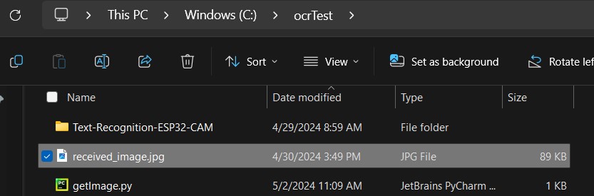
When the query returns the image, it is saved in the same directory as the python executable is located. The binary data is then decoded locally on the recipient device and turned back into an image. The image is then saved.
LastWriteTime         Length                Name
----                  -------------         ------ ----
4/29/2024   8:59 AM                         Text-Recognition-ESP32-CAM
4/29/2024   5:09 PM            933          getImage.py
4/29/2024   5:11 PM          72213          received_image.jpg
This is what my laptop directory looks like after running the Python program to receive images.
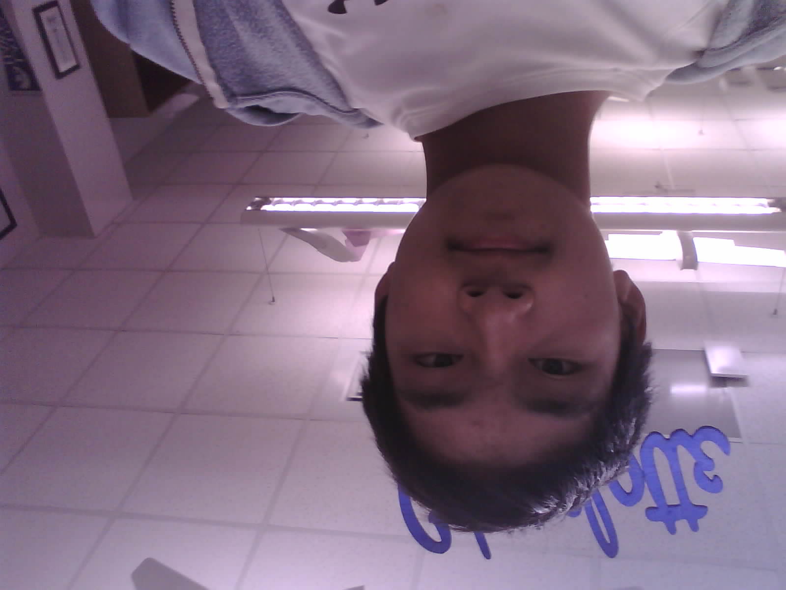
I then opened the image locally to verify that everything worked.
Because the entire process takes place wirelessly, there is no wired connection needed between the two devices. The ESP32CAM and Raspberry Pi just need to be powered on and connected to the same WiFi network.