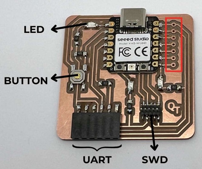
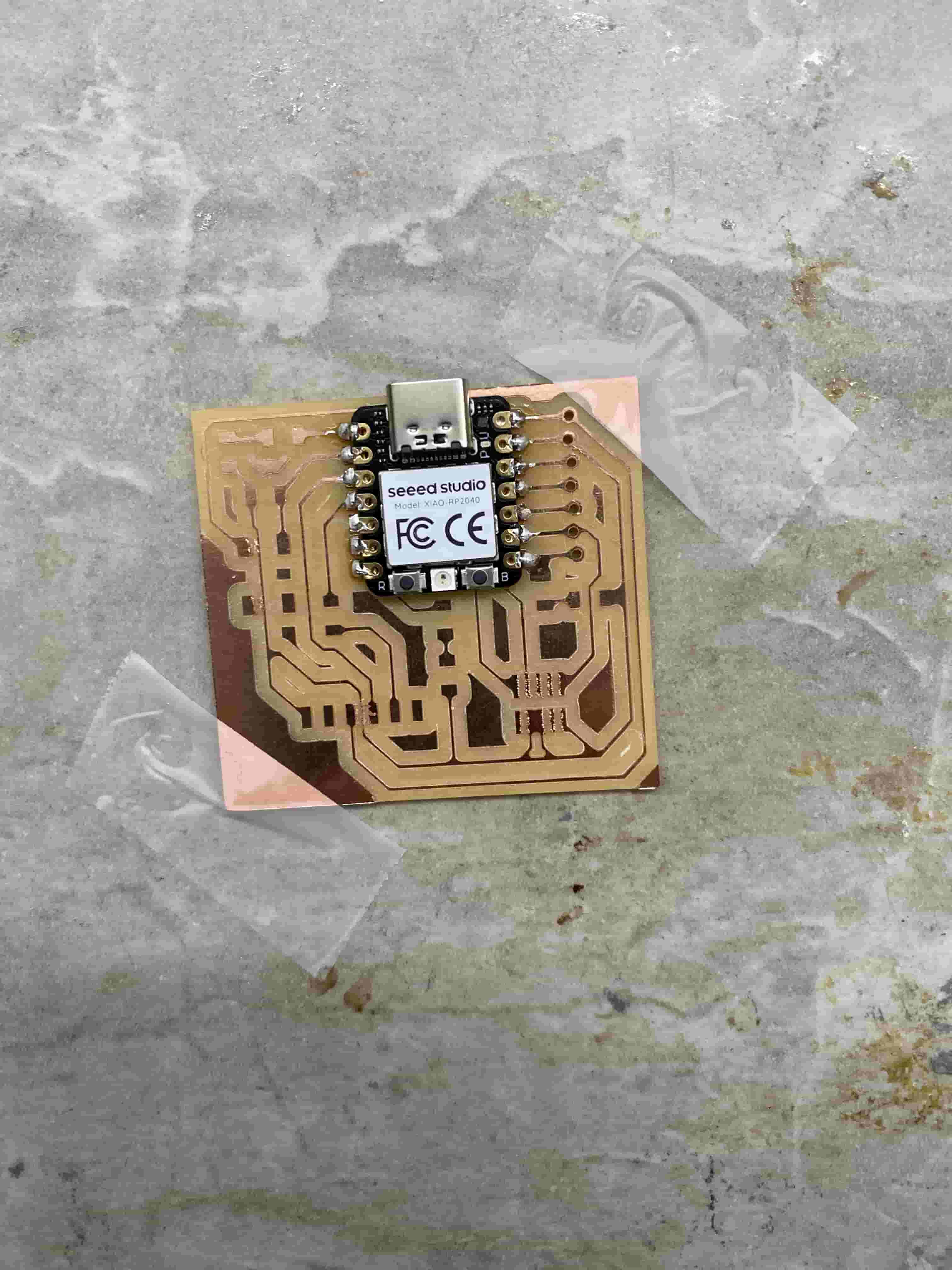
Seeed Xiao RP2040
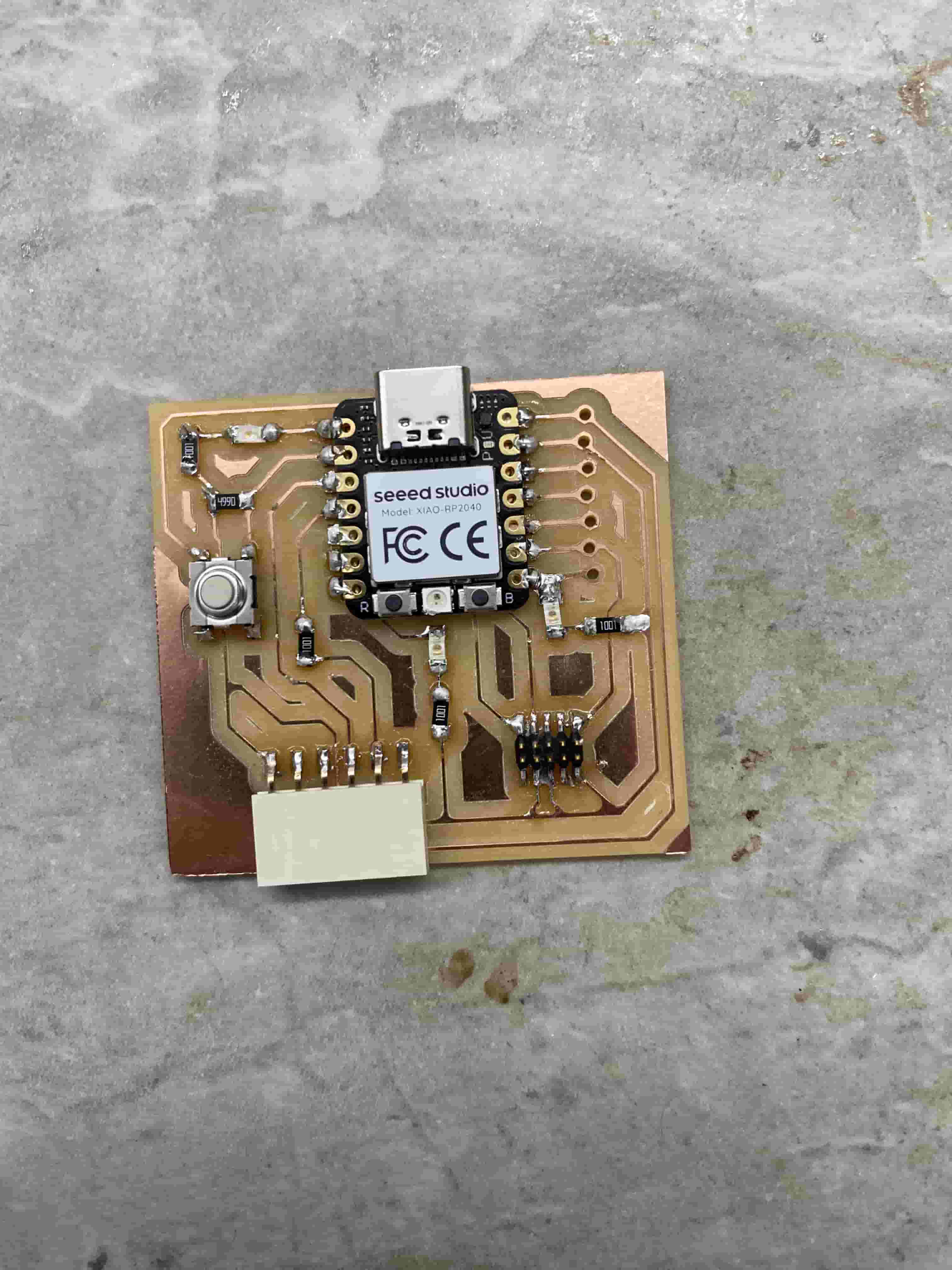
After milling the PCB board, it was time to solder on the components and test it out.
Materials
| Component | Amount |
| Seeed Xiao RP2040 Chip | 1 |
| PCB | 1 |
| Conn Header SMD 10POS 1.27mm | 1 |
| Conn Header SMD R/A 6POS 2.54mm | 1 |
| Tactile Switch SPST-NO Top Actuated Surface Mount | 1 |
| Blue LED | 3 |
| 1K Ohm Resistor | 4 |
| 499 Ohm Resistor | 1 |
Soldering
While soldering, I used the following references produced by Adrián Torres and David Taylor respectively.
 |
 |
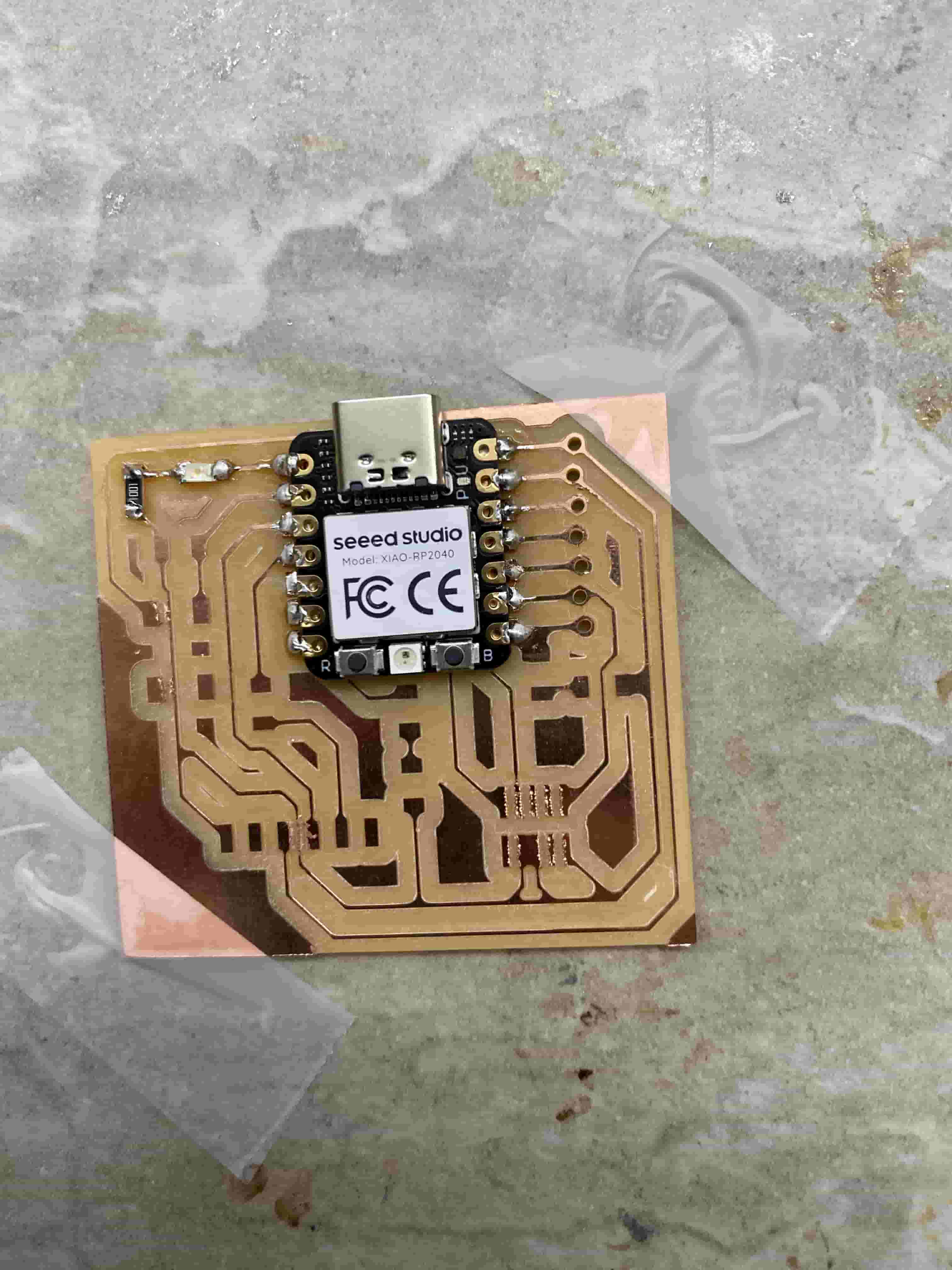
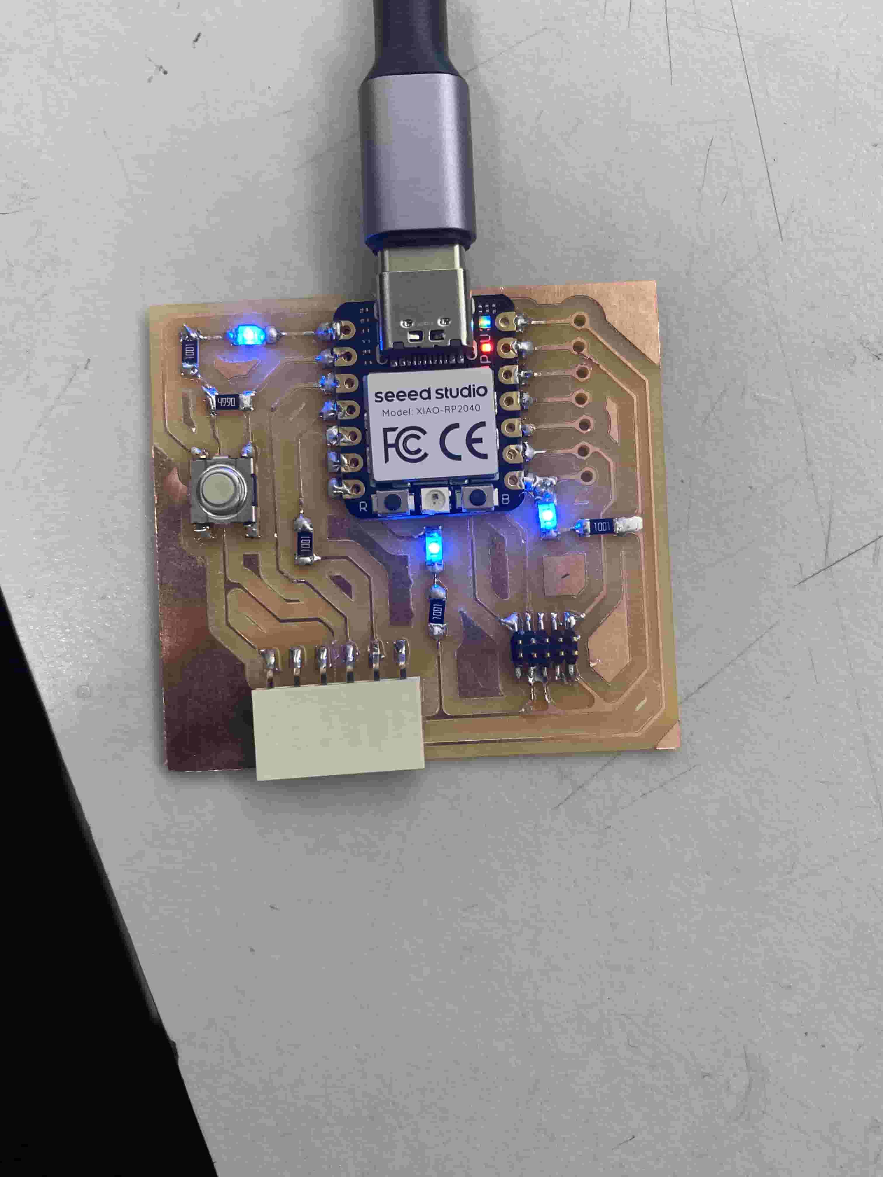
Before starting the soldering, I put a piece of kapton tape on the back of the chip so that the circuit would not short itself when it is plugged in.
I first aligned and soldered on the RP2040 chip. As the biggest component, I wanted to solder this on before any other parts.
Next, I soldered on the first blue LED at the top left, coming out of pin 26.
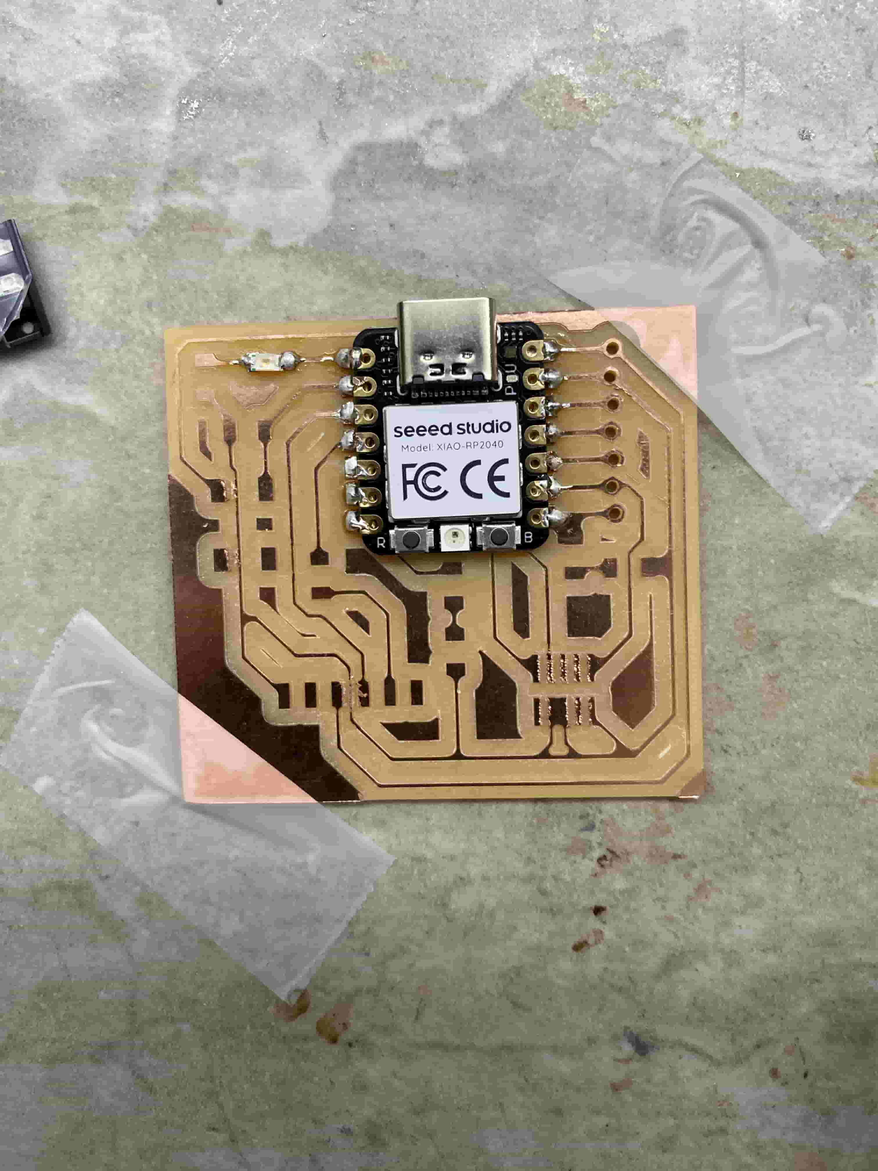
I then soldered on the 1k Ohm resistor for that LED.
I soldered on the button, along with 2 other resistors and an LED.
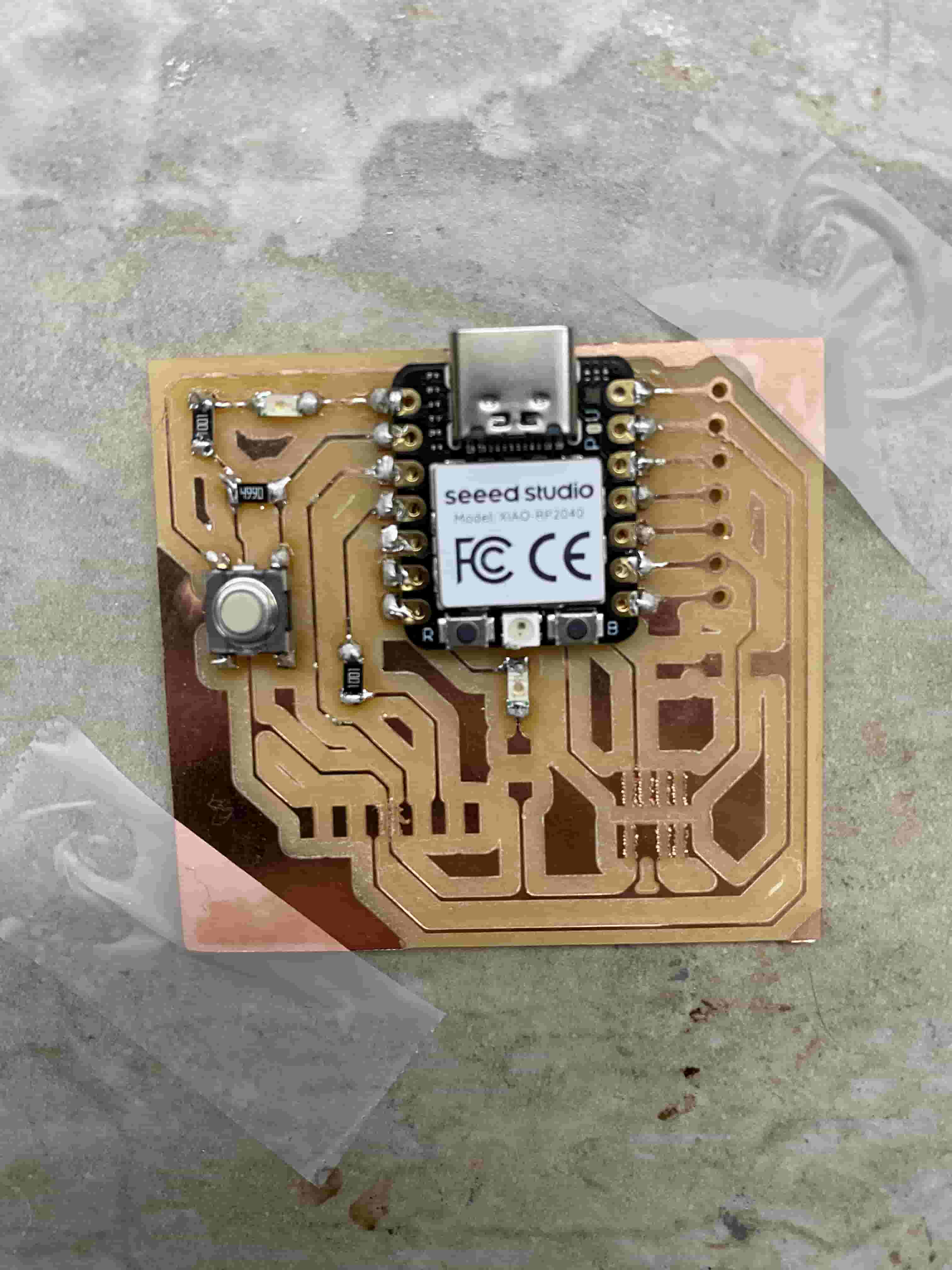
Next, I soldered on the Conn Header SMD 10POS 1.27mm, along with the final LED.
I then soldered on the remaining 2 resistors.
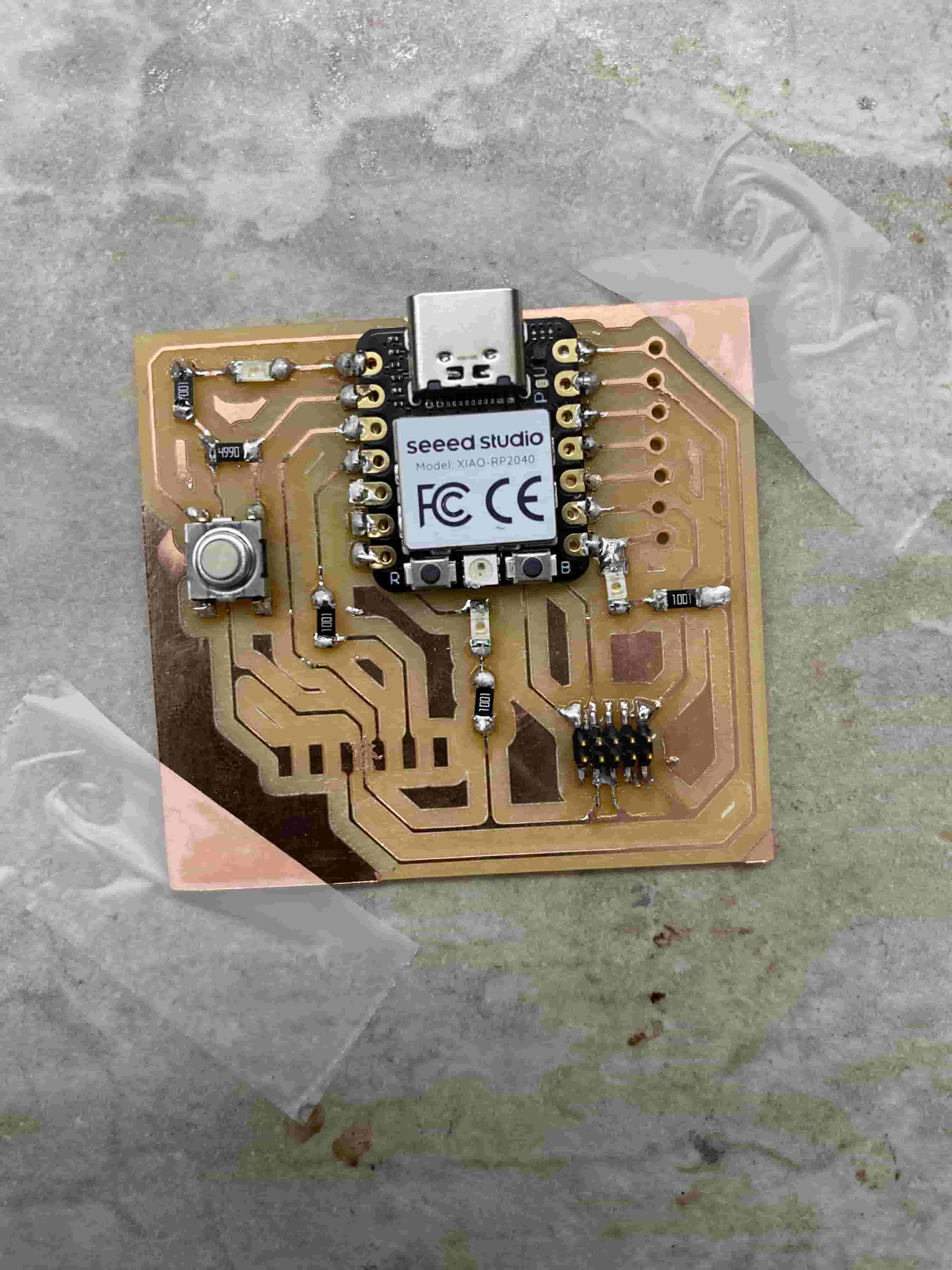
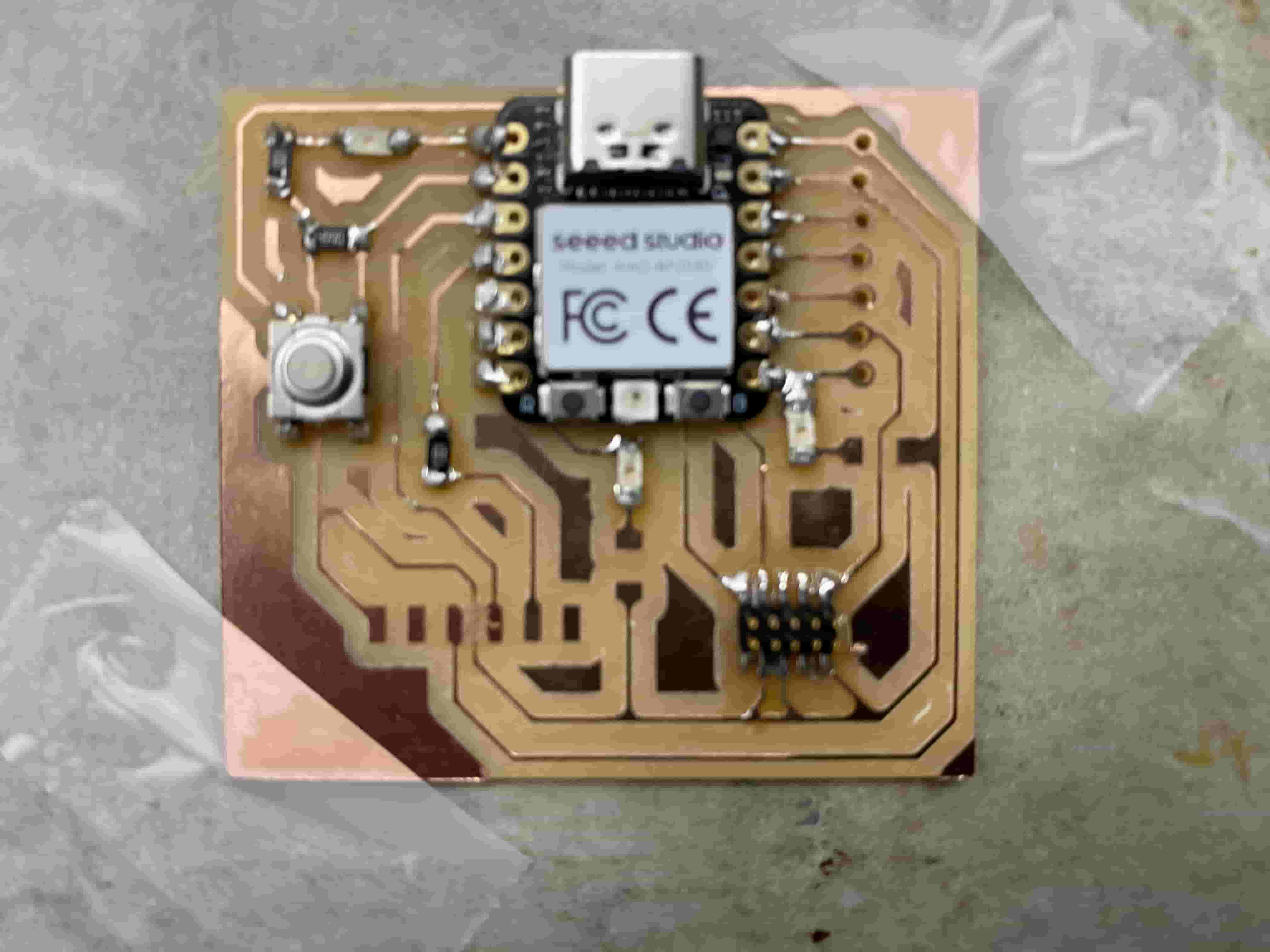
Finally, I soldered on the Conn Header SMD R/A 6POS 2.54mm.
Software
Board Selection
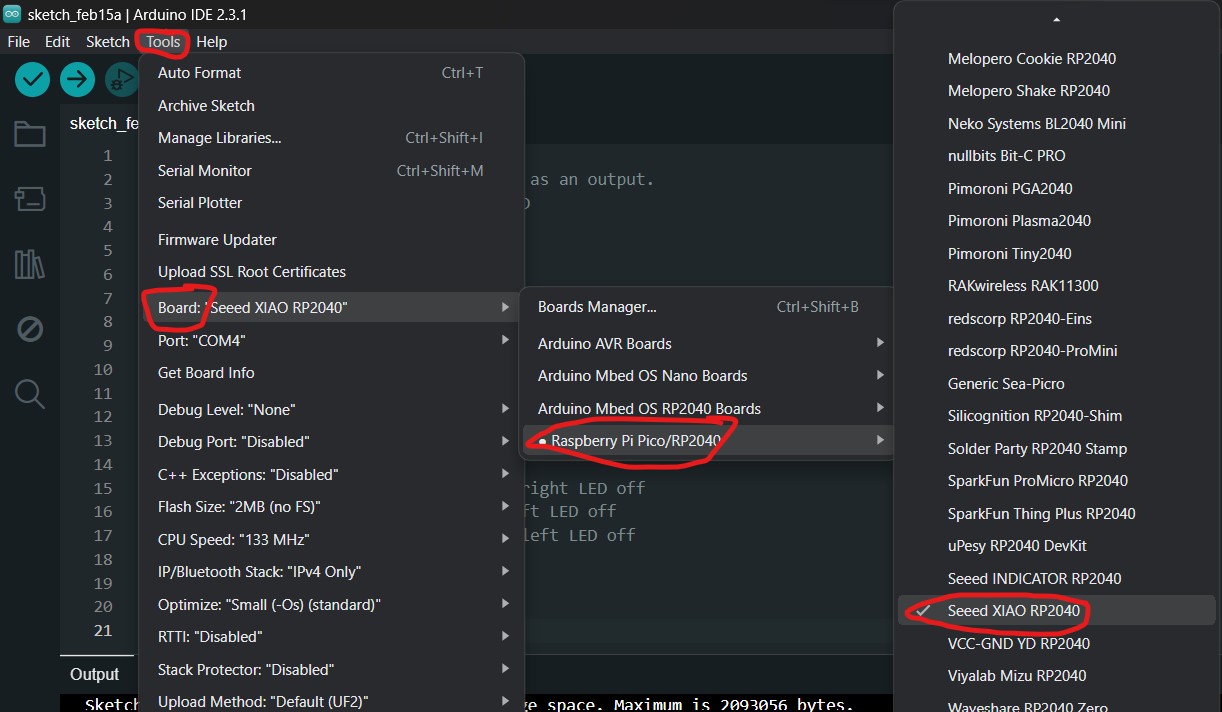
To download the required library for the Seeed Xiao 2040 chip, I had to add additional board URLs. I added the following URLs under the Additional Board URLs Manager in the Arduino IDE under File -> Preferences -> Additional Boards Manager. Each line represents a different URL. In other words, the URLs are seperated by a newline space.
https://github.com/earlephilhower/arduino-pico/releases/download/global/package_rp2040_index.json
https://raw.githubusercontent.com/espressif/arduino-esp32/gh-pages/package_esp32_dev_index.json
I was then able to select the correct board in the IDE.
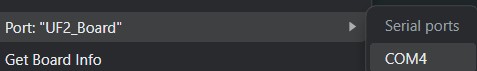
Port Selection Disabled
As I was trying out pushing more advanced programs onto the board, I encountered an issue where the "Port" selection button was grayed out and would not let me click into it.
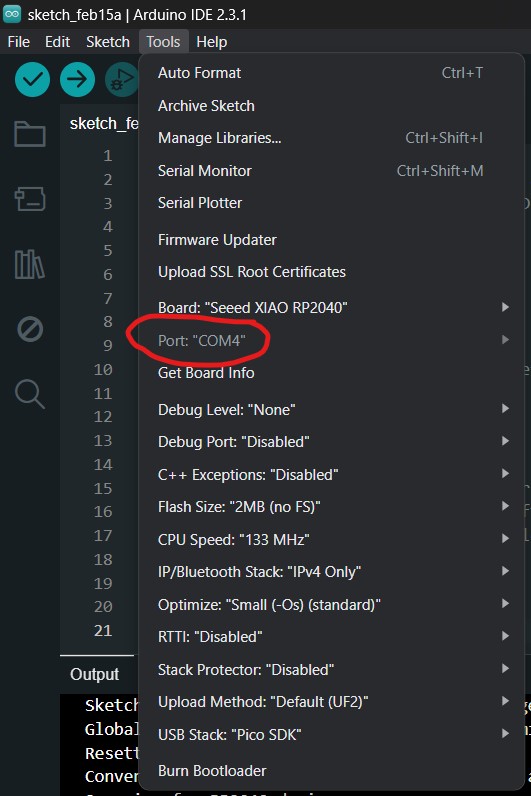
I searched for a solution online and found that I needed to reinstall/update a driver for the chip. However, under my Windows 11 Device Manager panel, the device was unrecognized by my computer and I had to manually find a zip file online to use as a driver. After spending about an hour going down this rabbit hole, I eventually realized that I could have simply reset the board. I did this by holding down the bootload button (indicated with a capital B) and clicking the reset button (indicated by a capital R).
After resetting the board, the Port selection started working again and recognized the RP2040's UF2 bootloader.
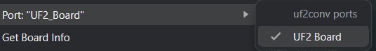
I then selected the UF2 bootloader option. At this point, the chip will accept uploaded code. As such, I sent the blinking program (any program would suffice) and the code worked on the chip. After the code was compiled and uploaded, the Port selection fixed itself and returned to the usual COM port selection.
Programming
LED Blinking
To test the circuit board, I wrote a simple program to blink all 3 LEDs that I sent to my fellow classmates. The LEDs are connected to pin 0, 1, and 26 respectively.
void setup() {
  pinMode(1, OUTPUT); //bottom right LED
  pinMode(26, OUTPUT); //top left LED
  pinMode(0, OUTPUT); //bottom left LED
}

void loop() {
  digitalWrite(1, HIGH); //turns bottom right LED on
  digitalWrite(26, HIGH); //turns top left LED on
  digitalWrite(0, HIGH); //turns bottom left LED on

  delay(1000); //waits for 1 second

  digitalWrite(1, LOW); //turns bottom right LED off
  digitalWrite(26, LOW); //turns top left LED off
  digitalWrite(0, LOW); //turns bottom left LED off

  delay(1000); //waits for 1 second
}
After uploading it, all of my LEDs worked without any issues!
 |
Button-Controlled LEDs
I then created a program that would turn on the LEDs when a button is pressed. The button is connected to pin 27.
void setup() {
  // Initialize LED pins as outputs
  pinMode(1, OUTPUT); // Bottom right LED
  pinMode(26, OUTPUT); // Top left LED
  pinMode(0, OUTPUT); // Bottom left LED

  // Initialize the button pin as an input
  pinMode(27, INPUT_PULLUP); // Button tactile switch on pin 27
}

void loop() {
  // Read the state of the button
  int buttonState = digitalRead(27);

  // If the button is not pressed, turn off the LEDs
  if (buttonState == LOW) { // The button is not pressed
    digitalWrite(1, LOW); // Turn off bottom right LED
    digitalWrite(26, LOW); // Turn off top left LED
    digitalWrite(0, LOW); // Turn off bottom left LED
  }

  // The button is pressed
  else {
    digitalWrite(1, HIGH);  // Turn on bottom right LED
    digitalWrite(26, HIGH); // Turn on top left LED
    digitalWrite(0, HIGH); // Turn on bottom left LED
  }
}
This video demonstrates the code in action.
Button Toggling LEDs
I wanted to create a program that would allow the button to act as a toggle for the LEDs. The LEDs would begin in the off state, then turn on when the button is pressed and vice versa. This program was slightly more difficult to write than the others, but also far more interesting.
// Define LED and Button pins as global variables
int ledPins[] = {0, 1, 26};
int buttonPin = 27;

// Variable to store the LED state
bool ledState = false;

// Variable to store the last button state
int lastButtonState = LOW;

void setup() {
  // Initialize LED pins as outputs
  for (int i = 0; i < 3; i++) {
    pinMode(ledPins[i], OUTPUT);
  }

  // Initialize the button pin as an input
  pinMode(buttonPin, INPUT_PULLUP);
}

void loop() {
  // Read the state of the button
  int buttonState = digitalRead(buttonPin);

  // Check if the button is pressed. The second part of the conditional ensures that the button only triggers the toggle once per actual press down.
  if (buttonState == LOW && lastButtonState == HIGH) {
    ledState = !ledState;

    // Toggle the LEDs
    for (int i = 0; i < 3; i++) {
      digitalWrite(ledPins[i], ledState ? HIGH : LOW);
    }

    // Debounce delay
    delay(50);
  }

  // Update the last button state
  lastButtonState = buttonState;
}
Here is the program running on the board: