Servo
Breadboard
I decided that I wanted to control a servo as my output device. At first, I wanted to use the board that I created in Week 8. However, I didn't create any power or ground external connector pins that would allow me to connect a servo, a critical flaw of the board that I didn't realize in week 8. However, I still used this board to test that my understanding and wiring for the servo was correct by using a breadboard. The breadboard allowed me to create additional pin connections for power and ground.
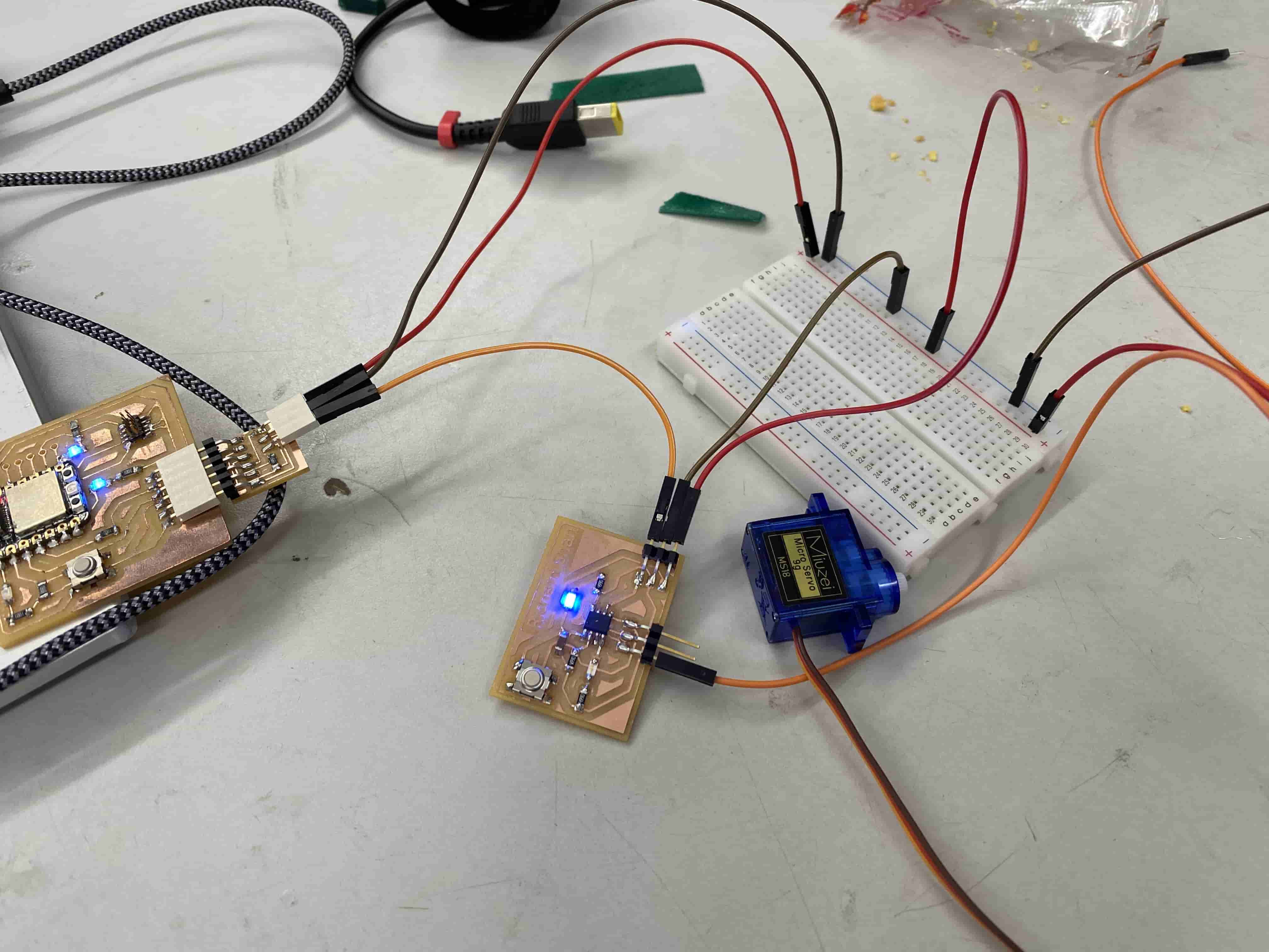
In this setup, I have connected the VCC and GND output pins of the Quentorres board to a breadboard, which is then connected to the VCC and GND pins of my ATTiny412 board. This effectively creates more pin openings that I can connect to VCC and GND. The UPDI is still wired directly from the Quentorres to the ATTiny412 board because I do not need to connect anything else to it. The servo data pin itself is pin 3 of the ATTiny412, or pin 1 in Arduino.
After doing some research on how servos worked, I came up with this code. This is a servo sweep program.
#include <Servo.h>

Servo servo;

void setup() {
  servo.attach(1);  // attaches the servo on pin 1 to the servo object
}

void loop() {
  for (int pos = 0; pos <= 180; pos += 1) {
    // goes from 0 degrees to 180 degrees in steps of 1 degree
    servo.write(pos);              // tell servo to go to position in variable 'pos'
    delay(15);                       // waits 15ms for the servo to reach the position
  }
  for (int pos = 180; pos >= 0; pos -= 1) {
    // goes from 180 degrees to 0 degrees
    servo.write(pos);              // tell servo to go to position in variable 'pos'
    delay(15);                       // waits 15ms for the servo to reach the position
  }
}
Here is a video of the servo working through the breadboard.
PCB
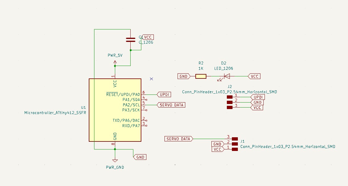
Because breadboards are uncouth, I decided to design a really simple ATTiny412 board that would control the servo and be programmed through the Quentorres. This board is incredibly simple and was created for one sole purpose: spin the servo. I include a power ground capacitor, a power indicator LED with a resistor, and a set of connector headers for VCC, GND, and DATA that would control the servo. Here is the schematic.
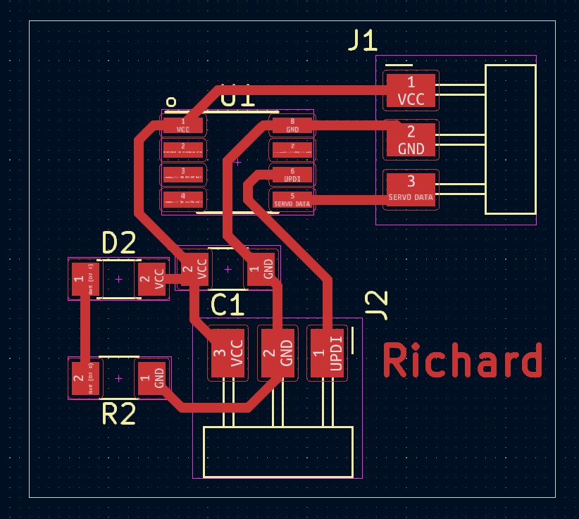
Here is my PCB design after routing the traces.
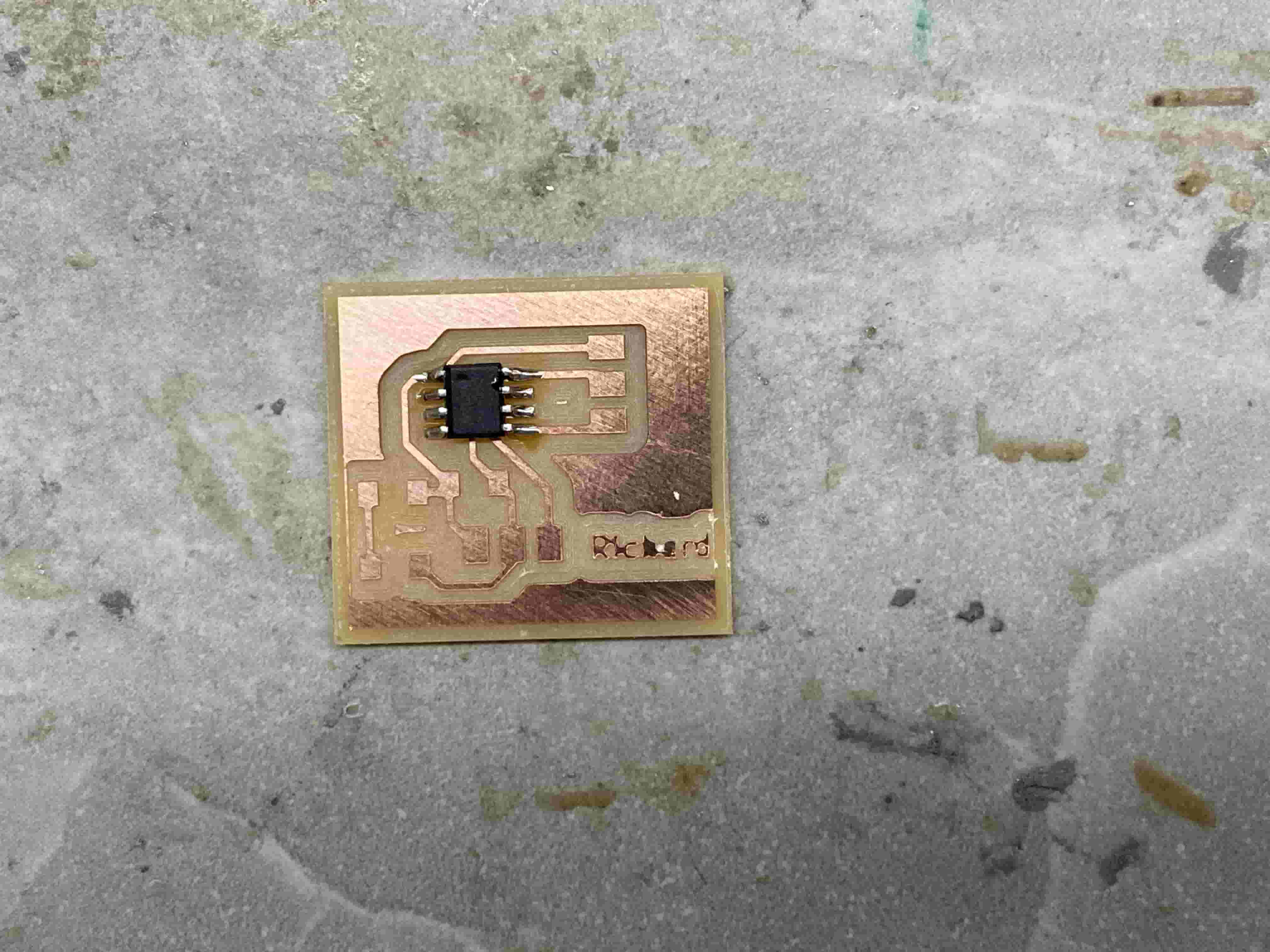
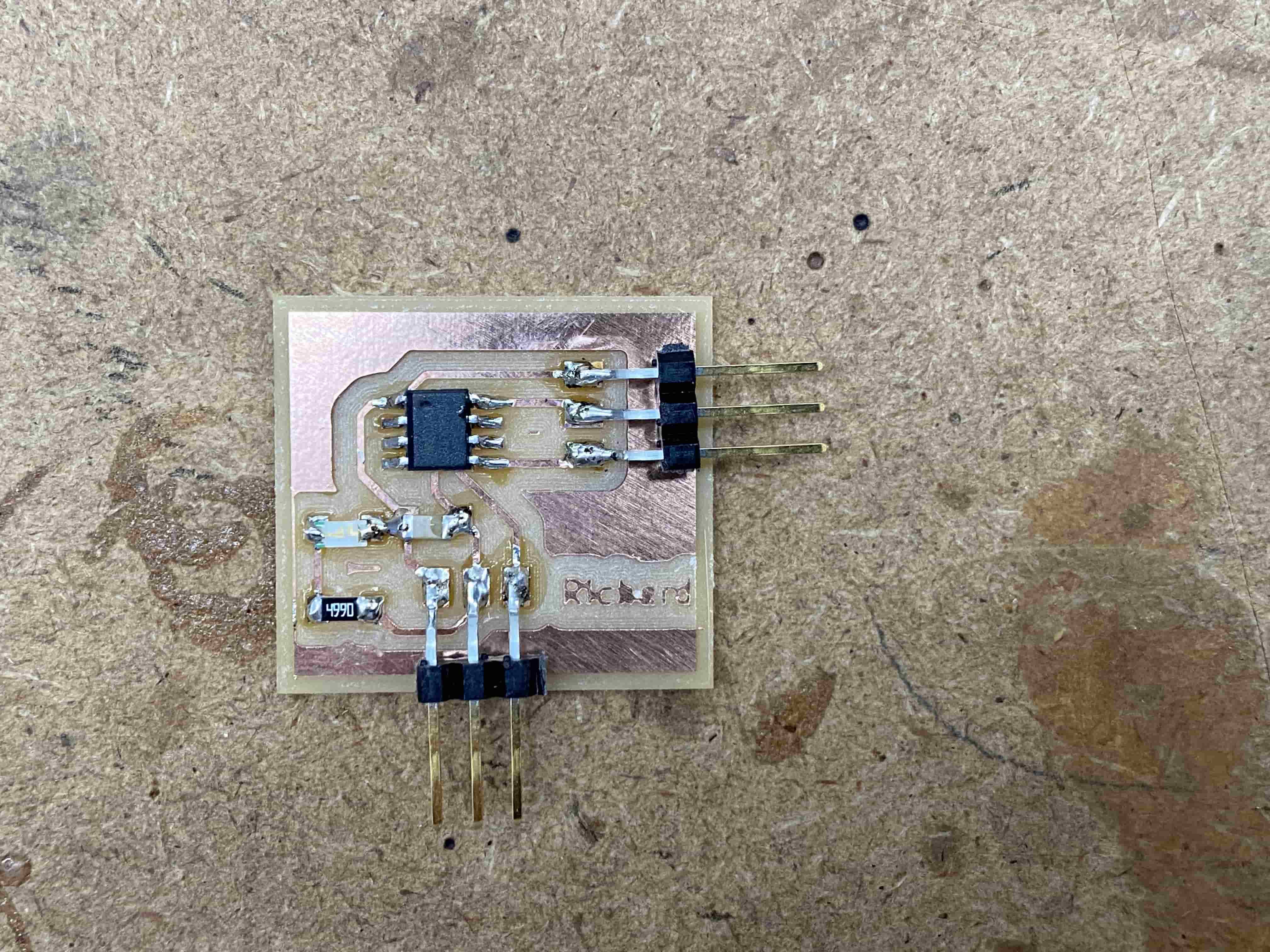
I then exported the design as a GBR file and milled it. Here is my milled board with the ATTiny412 soldered on.
Here is the board after I soldered on the remaining capacitor, resistor, LED, and conn pin headers.
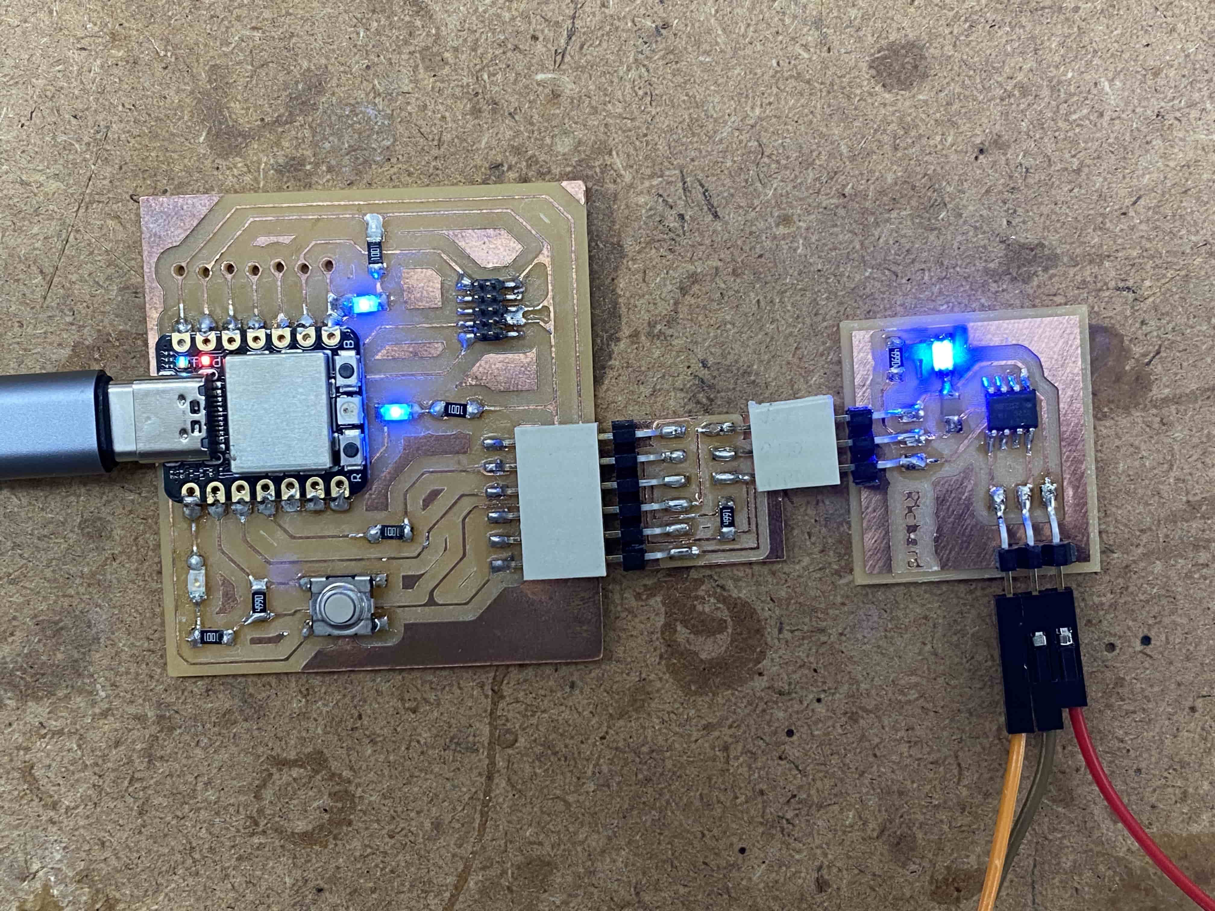
I then connected the board to the RP2040 board via the adapter I made previously. When I plugged everything in, the power indication LED turned on - a good sign!
I then slightly modified the original breadboard program to use ATTiny412 pin 5, or Arduino pin 3.
#include <Servo.h>

Servo servo;

void setup() {
  servo.attach(3);  // attaches the servo on pin 3 to the servo object
}

void loop() {
  for (int pos = 0; pos <= 180; pos += 1) {
    // goes from 0 degrees to 180 degrees in steps of 1 degree
    servo.write(pos);              // tell servo to go to position in variable 'pos'
    delay(15);                       // waits 15ms for the servo to reach the position
  }
  for (int pos = 180; pos >= 0; pos -= 1) {
    // goes from 180 degrees to 0 degrees
    servo.write(pos);              // tell servo to go to position in variable 'pos'
    delay(15);                       // waits 15ms for the servo to reach the position
  }
}
Here is the servo turning, this time with no breadboard.
I then attached a component to the top of the servo gear so that in the video, its movement can be seen more explicitly.