PCB Programming
To test my board, I decided to write a simple blink program to blink the programmable LED on my board.
Setup
I first downloaded the megaTinyCore library from GitHub and installed its boards via Arduino IDE's Boards Manager.
After I installed megaTinyCore, I configured my Arduino IDE settings to the following specifications in preparation for programming the ATTiny412.
| Setting | Specification |
| Board | megaTinyCore -> ATtiny412 |
| Port | COM8 |
| Chip | ATtiny412 |
| Programmer | SerialUPDI - Fast: 4.5v+ 460800 baud |
Programming
Since my programmable LED was coming out of pin 4 on the ATTiny412 chip, I originally wrote this program.
void setup() {
  pinMode(4, OUTPUT);
}

void loop() {
  digitalWrite(4, HIGH);
  delay(200);
  digitalWrite(4, LOW);
  delay(200);
}
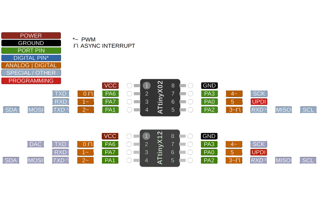
The code uploaded successfully but the programmable LED still wasn't turning on. However, I realized that the pinout of the ATTiny did not correspond to the pinout when being programmed in the Arduino IDE. I used this image that I found online and realized that in order to program the pin 4 LED, I needed to change the digitalWrite pin to 2. I believe that if I were to write a more low-level program, it would work with specifying pin 4.
After I changed the pin from 4 to 2, my code looked like this.
void setup() {
  pinMode(2, OUTPUT);
}

void loop() {
  digitalWrite(2, HIGH);
  delay(200);
  digitalWrite(2, LOW);
  delay(200);
}
Sketch uses 446 bytes (10%) of program storage space. Maximum is 4096 bytes.
Global variables use 10 bytes (3%) of dynamic memory, leaving 246 bytes for local variables. Maximum is 256 bytes.
SerialUPDI
UPDI programming for Arduino using a serial adapter
Based on pymcuprog, with significant modifications
By Quentin Bolsee and Spence Konde
Version 1.2.3 - Jan 2022
Using serial port COM8 at 460800 baud.
Target: attiny412
Set fuses: ['0:0b00000000', '2:0x02', '6:0x04', '7:0x00', '8:0x00']
Action: write
File: Path redacted for privacy
Pinging device...
Ping response: 1E9223
Setting fuse 0x0=0x0
Writing literal values...
Verifying literal values...
Action took 0.13s
Setting fuse 0x2=0x2
Writing literal values...
Verifying literal values...
Action took 0.15s
Setting fuse 0x6=0x4
Writing literal values...
Verifying literal values...
Action took 0.15s
Setting fuse 0x7=0x0
Writing literal values...
Verifying literal values...
Action took 0.13s
Setting fuse 0x8=0x0
Writing literal values...
Verifying literal values...
Action took 0.15s
Finished writing fuses.
Chip/Bulk erase,
Memory type eeprom is conditionally erased (depending upon EESAVE fuse setting)
Memory type flash is always erased
Memory type lockbits is always erased
...
Erased.
Action took 0.04s
Writing from hex file...
Writing flash...
[                                                  ]
[=======                                           ] 1/7
[==============                                    ] 2/7
[=====================                             ] 3/7
[============================                      ] 4/7
[===================================               ] 5/7
[==========================================        ] 6/7
[==================================================] 7/7
Action took 0.39s
Verifying...
Verify successful. Data in flash matches data in specified hex-file
Action took 0.05s
This time, the programmable LED started flashing! Here is my code in action.