Parametric Construction Kit
This week, we were challenged to laser cut a series of objects that could be used as a construction kit. I designed the kit in Fusion 360 where I could take advantage of parametric designing, defining and using variables to rapidly modify the model. For this design, I was inspired by Elaine Liu's creation.
Designing
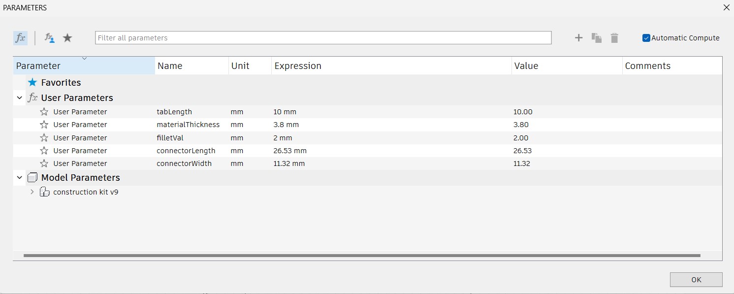
| Parameter Name | Description |
| tabLength | The length that each tab hole juts into the polygon |
| materialThickness | The thickness of the cardboard, used for determining the width of the tabs |
| filletVal | The size of the fillet for each tab joint |
| connectorLength | The length of the L-shape connectors |
| connectorWidth | The width of the L-shape connectors |
Hexagon
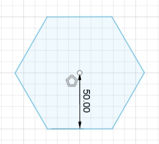
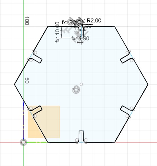
To start designing the hexagonal component, I created a polygon with six sides using the circumscribed polygon tool.
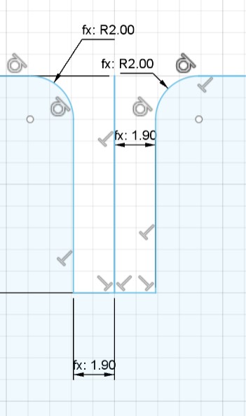
I then created a tab on one side of the hexagon. The tab was tabLength deep and materialThickness wide. Both sides were filleted by filletVal.
I then used Fusion's Circular Pattern tool to repeat the tab on each side of the hexagon. I repeated the tab for a total of 6 tabs and centered the pattern at the center of the hexagon.
Square
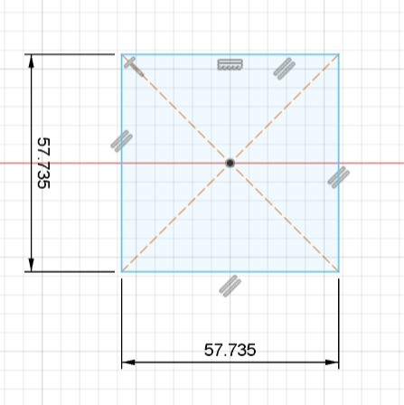
I first used the center rectangle tool to create a square. Each side of the square must be the same length as the length of a side of the hexagon to fit together properly. To find the side of the hexagon, you could simply create a line on the side in Fusion360 which would return the measurement. However, I chose to find this value mathematically.
 |
 |
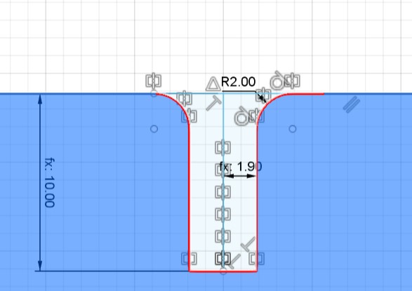
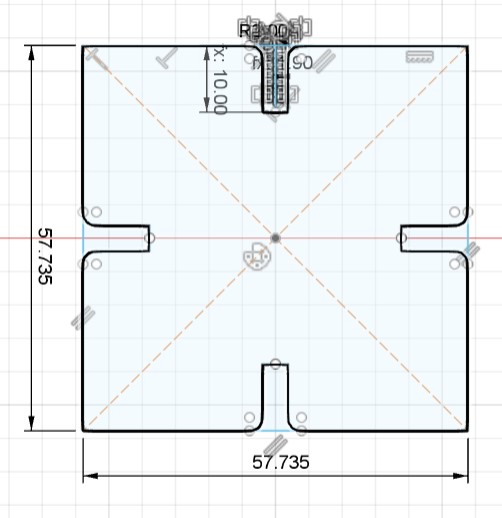
After creating the basic square outline, I created a tab at the midpoint of the top edge of the square. The tab is tabLength deep and materialThickness wide, with a fillet of filletVal.
I then used the circular pattern tool to create a total of 4 tabs on the square, with the center point of the square as the centerpoint of the circular pattern. This created a tab at the midpoint of each side of the square.
Connector
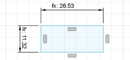
I started out by creating a rectangle that had dimensions connectorLength by connectorWidth.
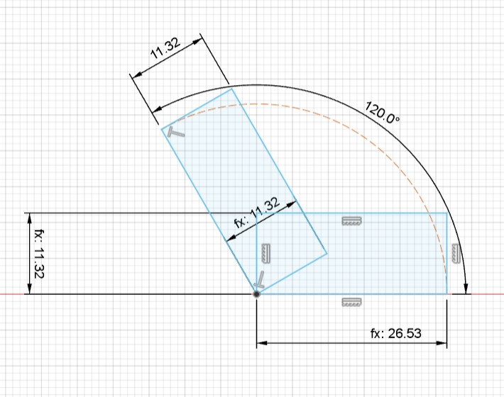
I then created another rectangle with the same dimensions at a 120 degree angle to the first rectangle (each interior angle of a hexagon is 120 degrees).
I then created a tab on the top part of the connector. The creation process is similar to making the tab on the hexagon. The tab is tabLength deep and materialThickness wide, with fillets of filletVal.
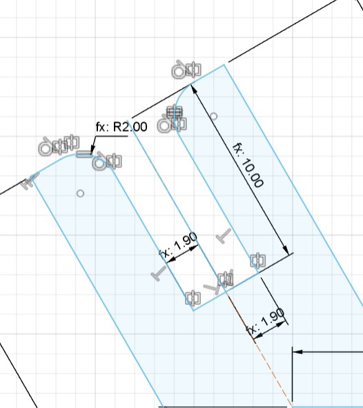
I then mirrored the tab across the centerline of the connector.
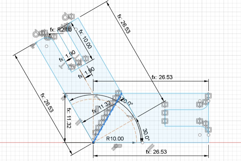
For this week, I forgot to factor in the kerf of the machine into the design. Luckily, the kerf of the laser cutter was small enough that it didn't noticeably affect the end result at all. However, in future designs, I will make sure to account for the kerf. This means that I will adjust my parameters for specific values that are vulnerable to being affected by kerf, such as the materialThickness (because the kerf means that the end result cut could have less tolerance for the actual cardboard than previous planned), and the connectorLength and connectorWidth values (to correct for kerf and ensure that the connector pieces are the dimensions that I actually intended to design them to be).
Assembly
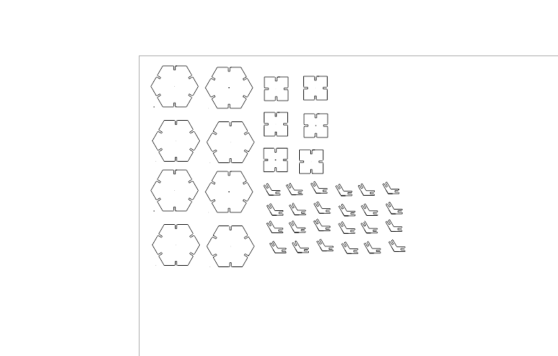
I first exported the Fusion360 file as a DXF and opened it in CorelDraw. In CorelDraw, I duplicated my designs until I had 8 hexagons, 6 squares, and 24 connectors and sent it to Epilog Engraver. Unfortunately, I miscalculated and was 12 connectors short, so I had to cut another 12 connectors afterwards.
 |
 |
I then sent the design to the laser cutter and cut the cardboard. I used our lab's default configuration for cutting cardboard. I selected cardboard as my cutting material and loaded the default settings of 100% power, 40% speed, and 10% frequency.
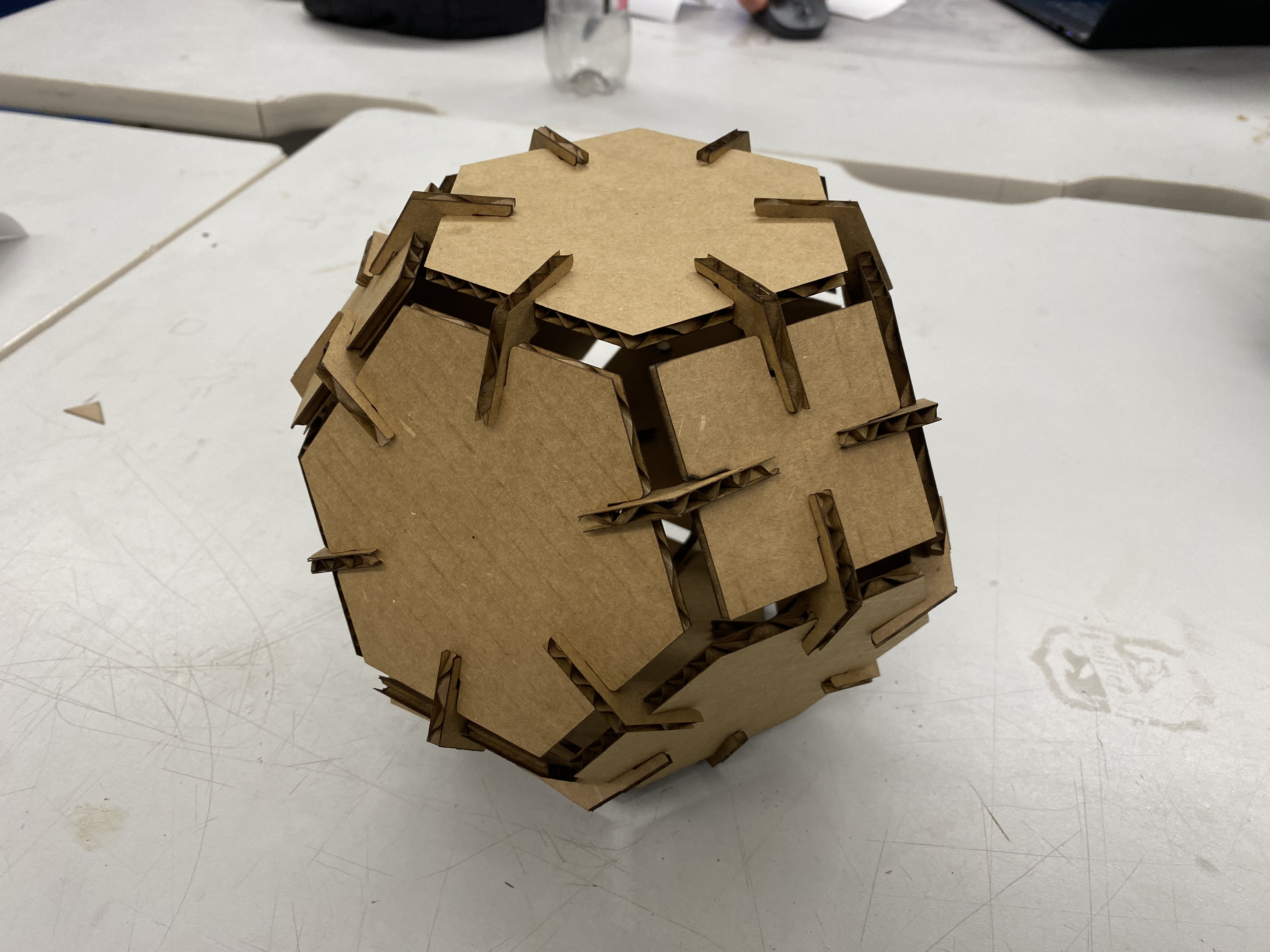
After pushing the pieces together, here is the final tetradecahedron.