Week 15. Wildcard week
This week is a fun week since we get to decide the machine and the assignment for ourselves. As the lead for the Zund in the JNWSFL, I decided I wanted to stick with the Zund, not really focusing on the design (fusion360 etc), but more on making a solid documentation on How to use the Zund.
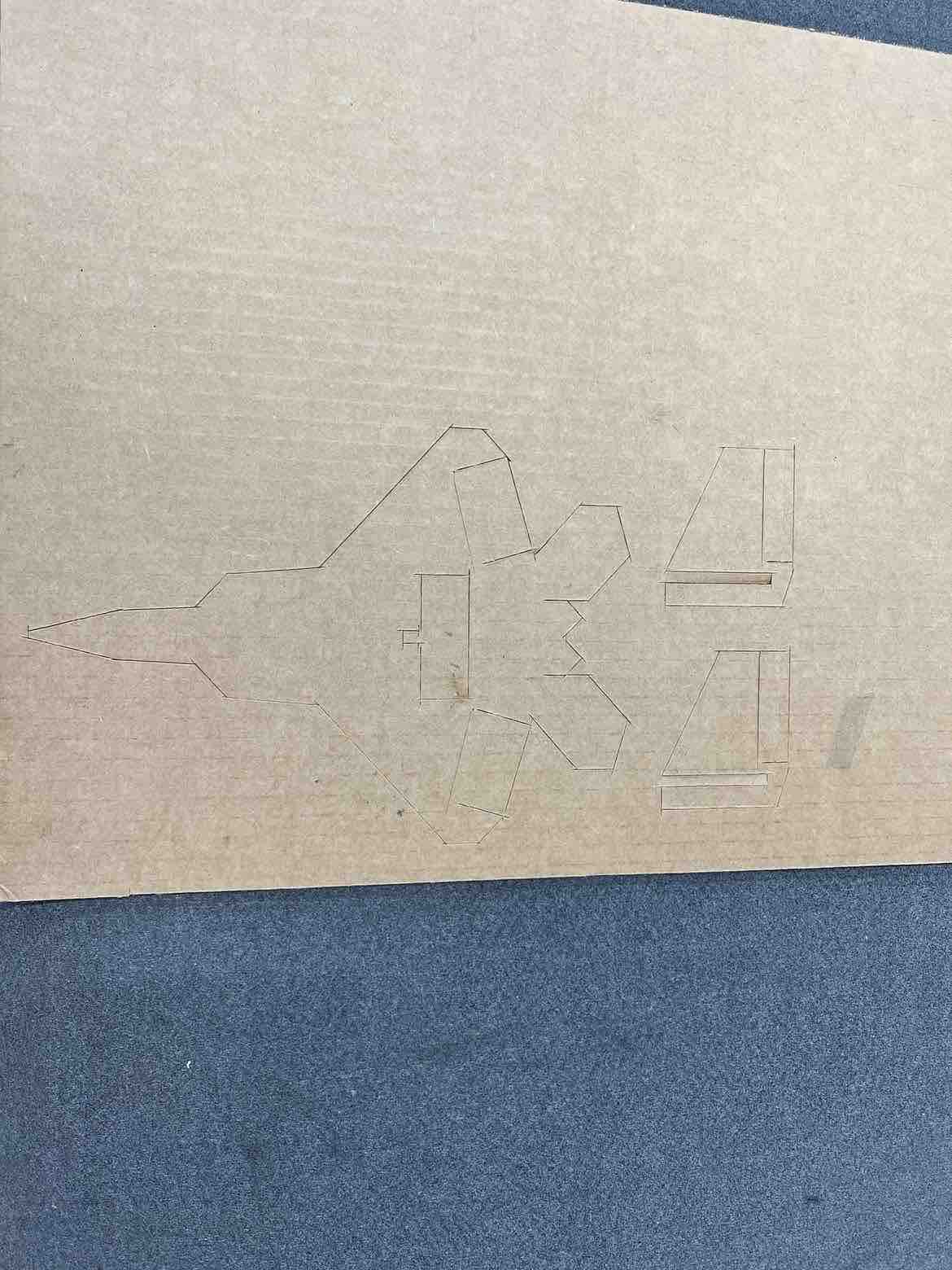
I kept it simple, and decided to design a simple 2D F22 Raptor using cardboard, with v-cuts to make the ailerons foldable. (Actually I did not keep it simple at all, I wanted to make a assemble-able 3D F22 using 2D parts but the design got too complex for our small foam boards so I fell back on a simple 2D design).
Fusion 360
Anyway, to design the 2D structure, I used Fusion360 and sketched out a simple shape of the F22 raptor and its two rudders.
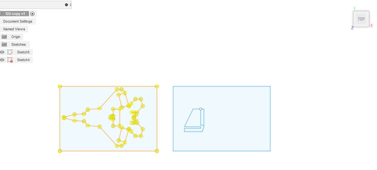
Once the design was done, I saved the sketch as a dxf file since thats a format the Zund software cutter can read.
The Zund G3-L2500
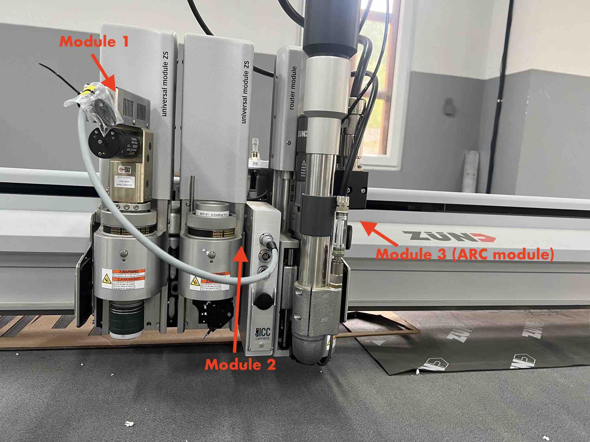
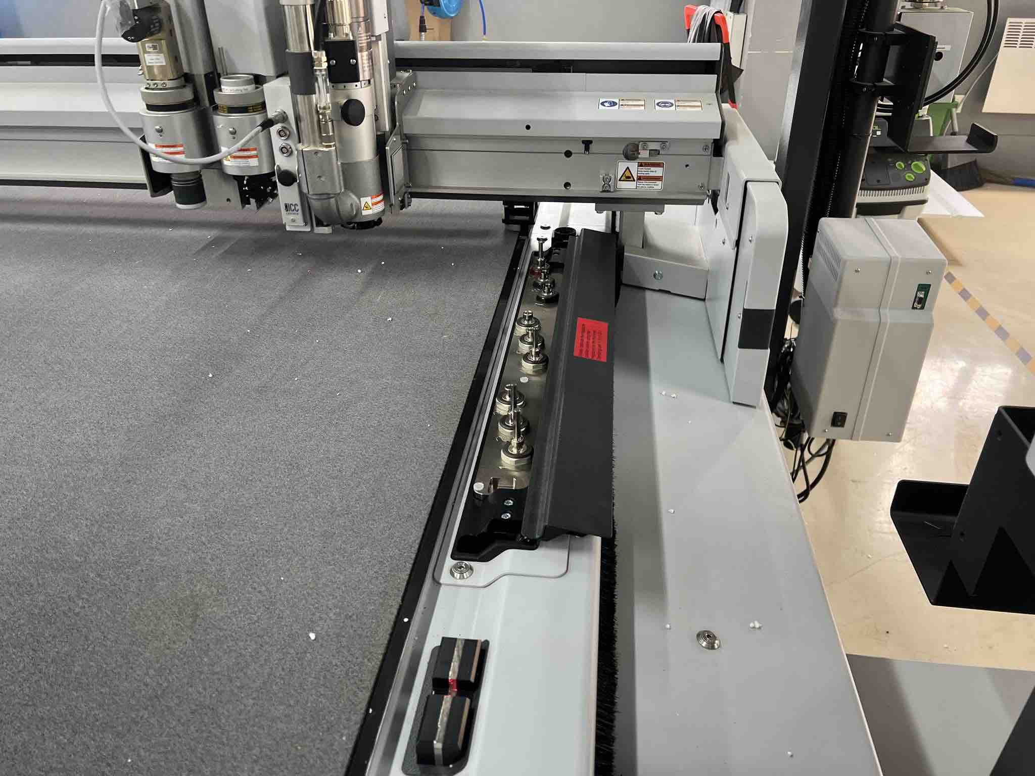
The Zund G3-L2500 is a 2D flatbed Digital cutter which can cut, draw, route, engrave, kiss-cut, and many more processes on a variety of different materials ranging from paper to carbon fiber to soft aluminum alloys. This is possible due to the Zund’s modular system which allows for easy interchange of modules and tools for specific functions and materials.
Work flow:
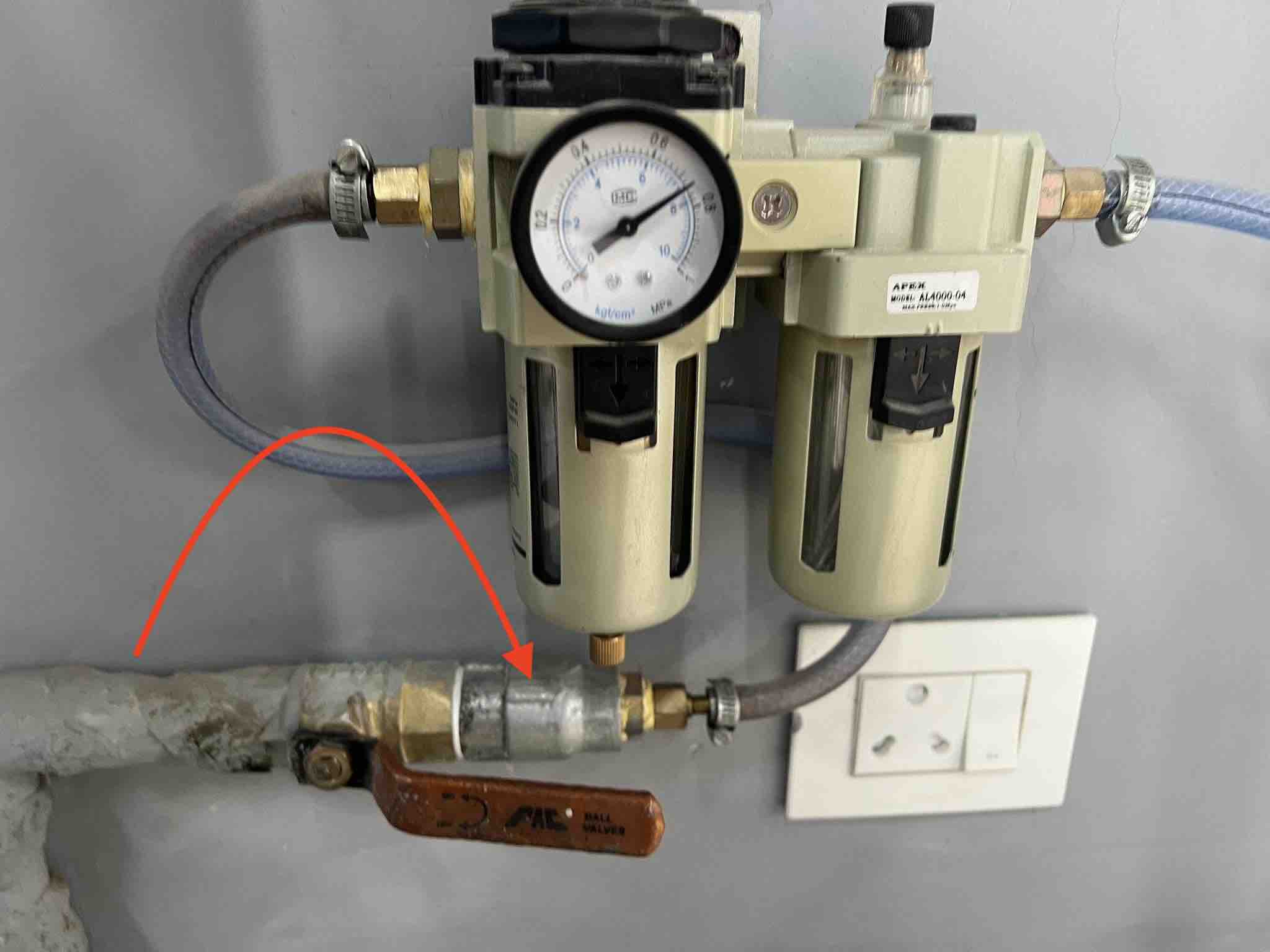
Powering the machine
- Turn on the compressor of the Zund
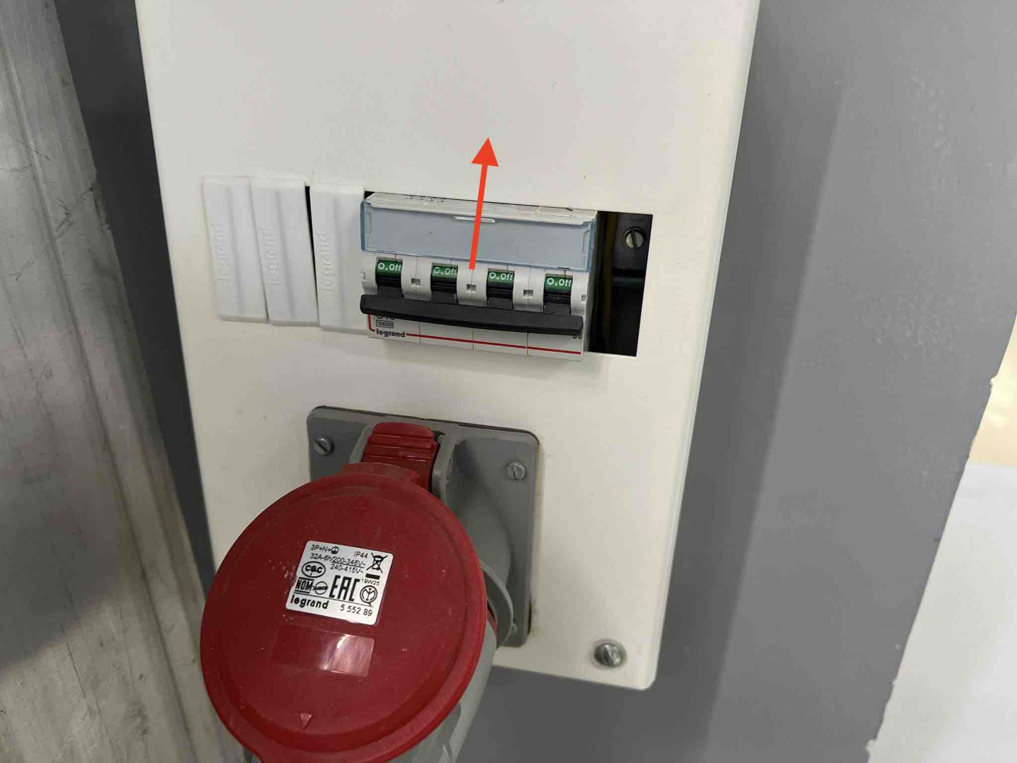
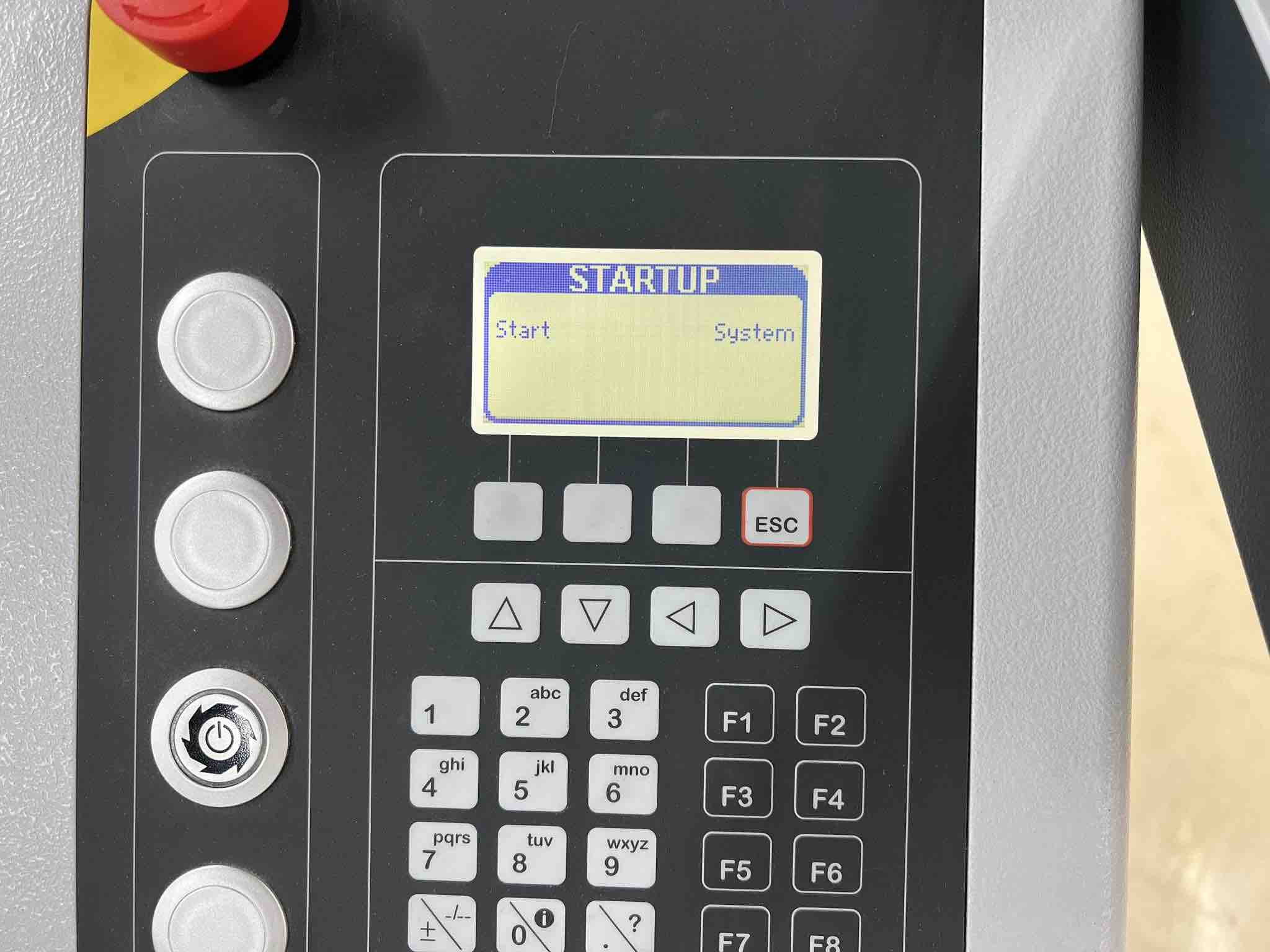
- Turn on the main power supply of the Zund. The Zund’s operating screen will power up
- Hit
F1to begin initializing the machine. (the operating screen will tell you that you can start with F1)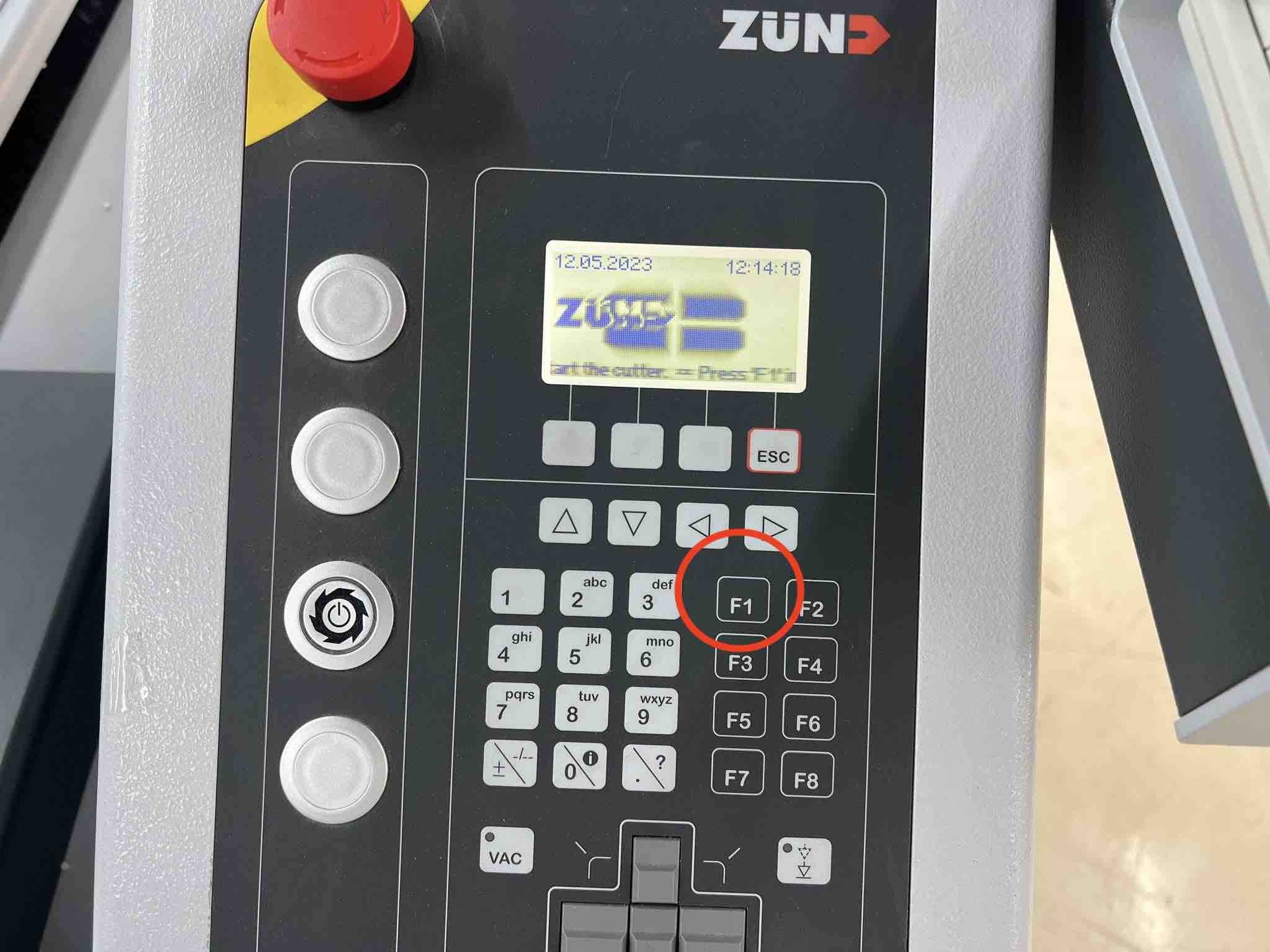
- After hitting F1 DO NOT touch anything while the machine initializes itself. The modules will come towards the PC and operating screen once initialization is done.
- Turn on the PC in the meanwhile
Initializing the tools
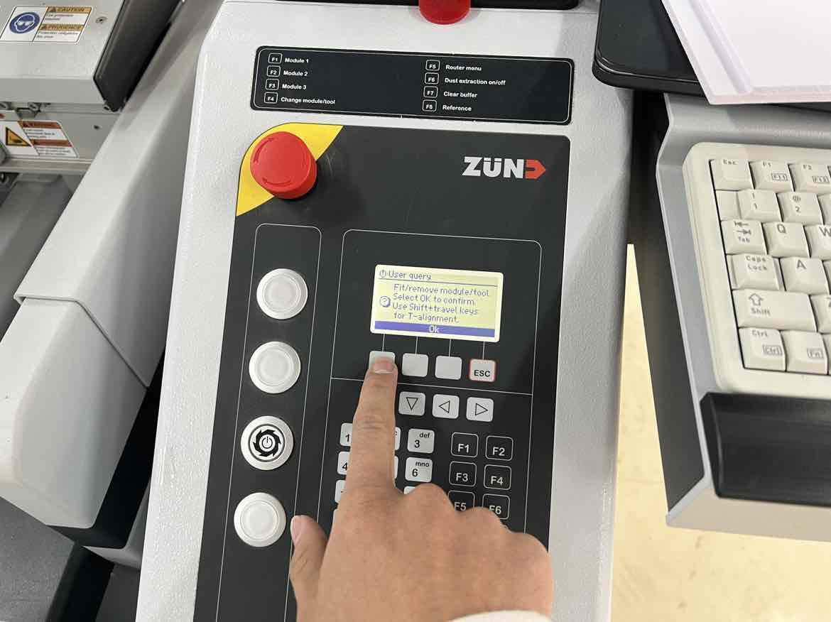
- Our Zund has three module slots. The operating screen will begin with module 1. Check that the tool displayed on the screen is the same as the the tool thats currently in the module 1 slot.
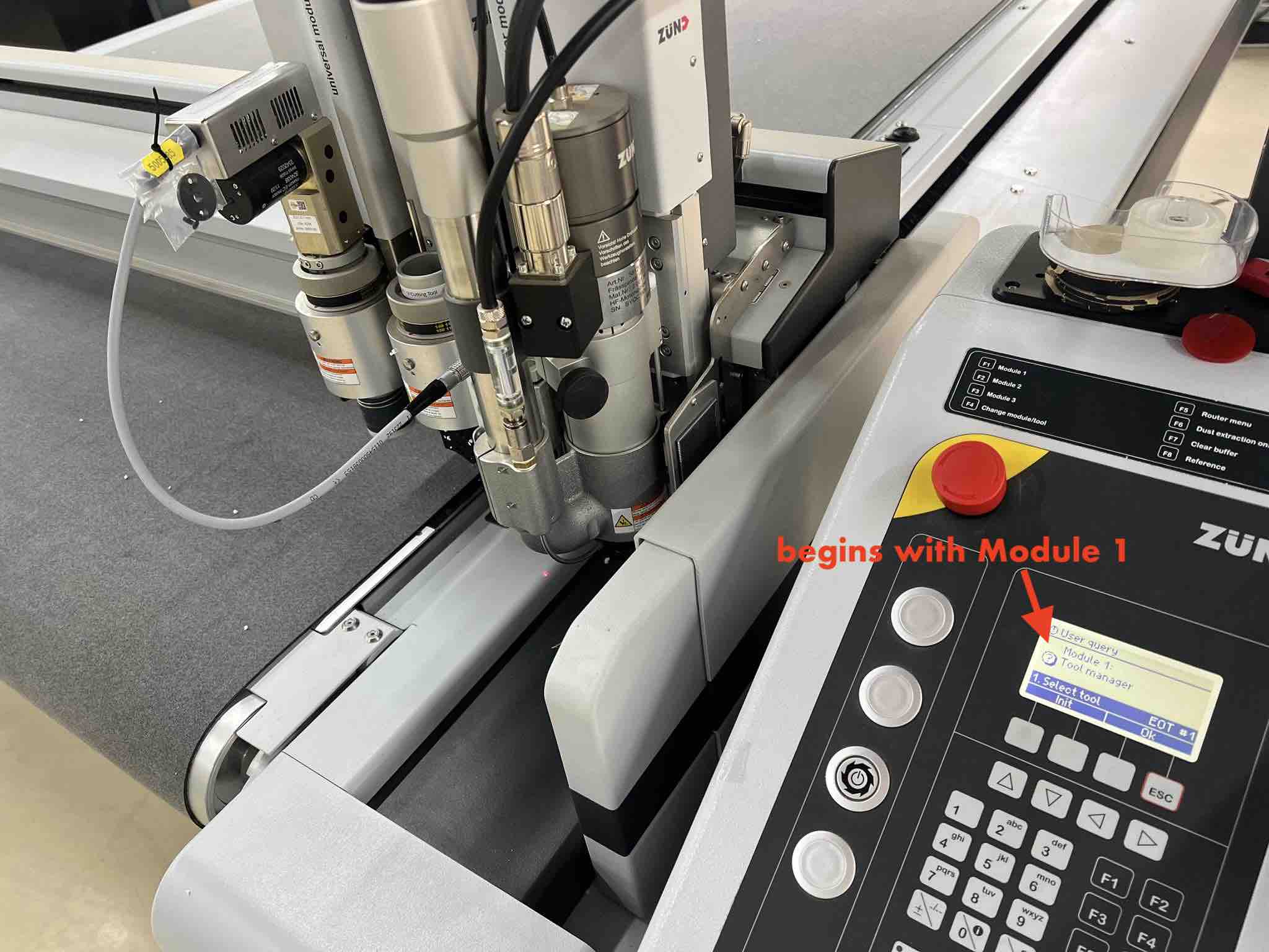
- After confirming, hit
init. This will take you to the initialization screen. - In the
Initializationscreen, hit2on the keypad toAuto init. Hit okay to start.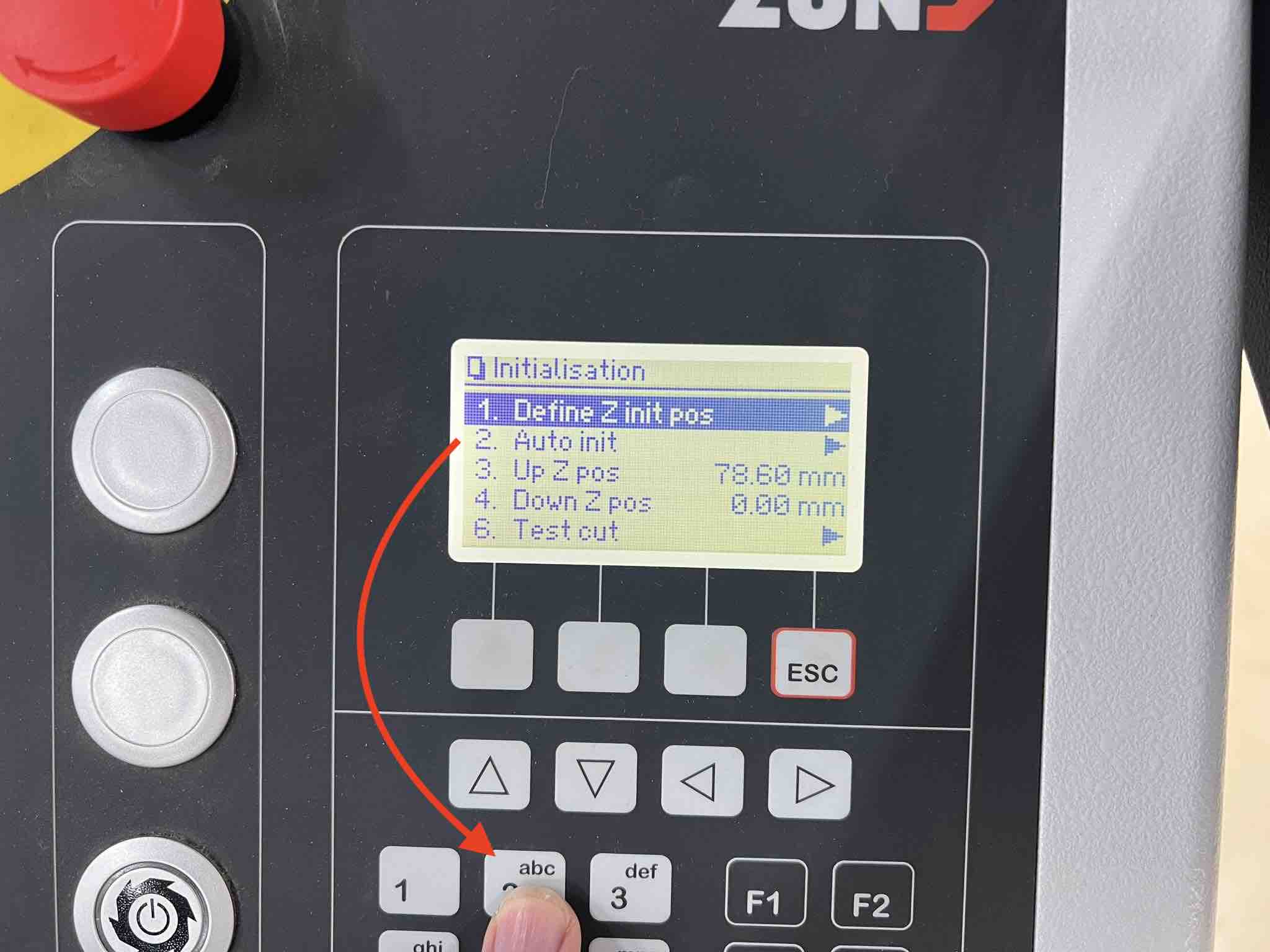
- Once the Auto initialization is done hit
ESCon the keypad to save that.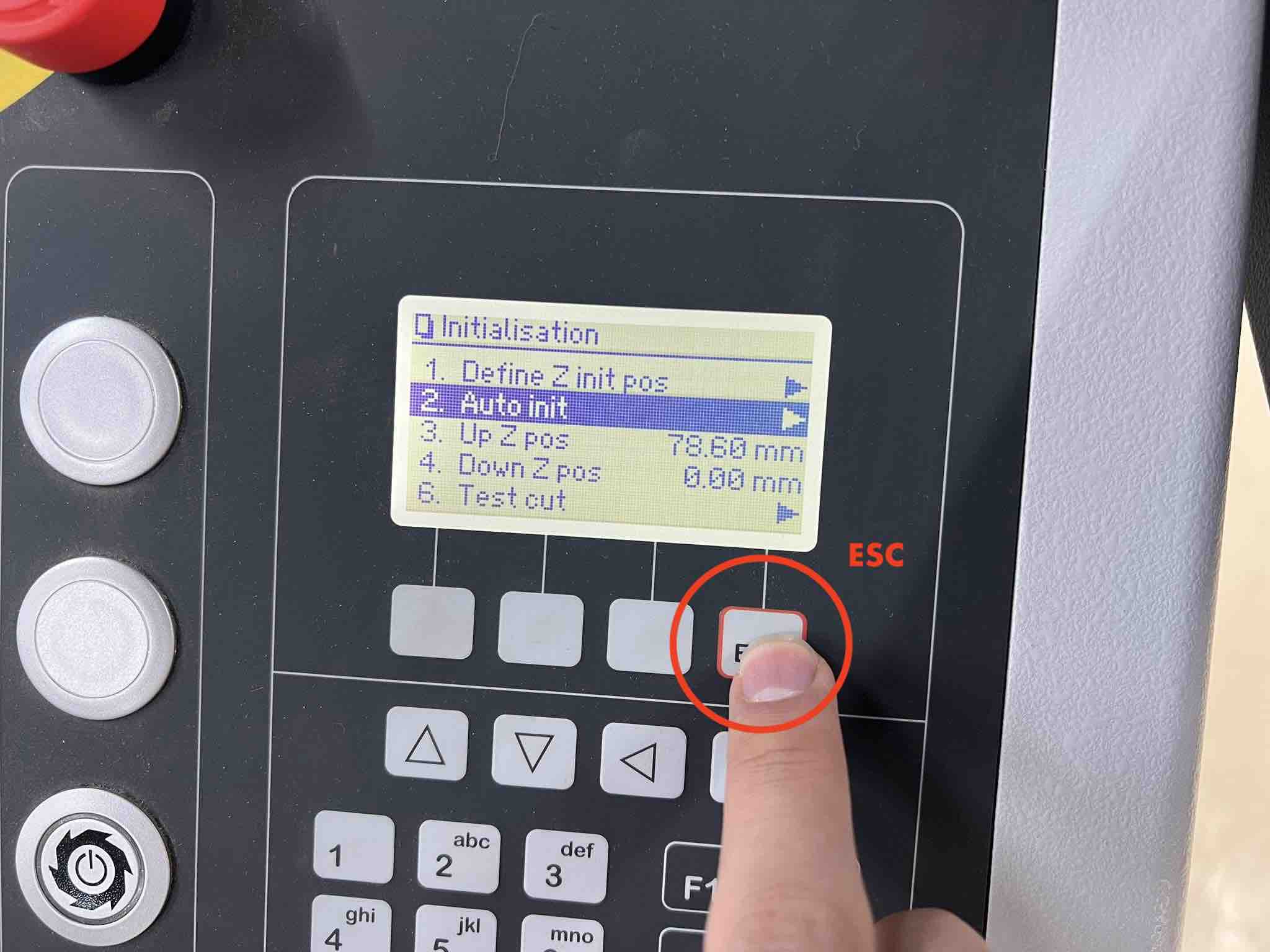
- Then the machine will move on to module 2. Ensure the tool displayed on the operating screen is the same as the tool in module 2 and conduct the same initialization process as above.
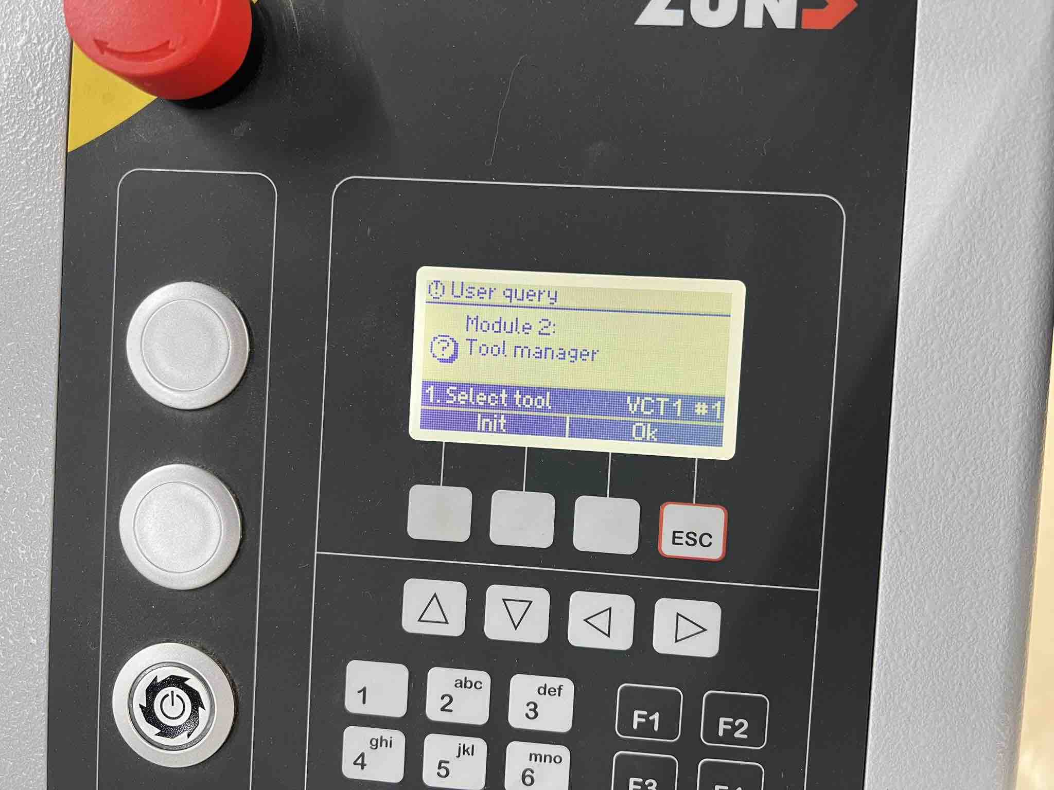
- Module 2 auto initializing:
- After initializing module 2 and its tool, the machine will move on the final module, module 3 or the routing module.
- Do the initialization routine as explained above and save it using ESC.
- Once the Initialization of all three are done, the machine’s operating screen will then prompt a
magazine scanto which all you have to do is hitok.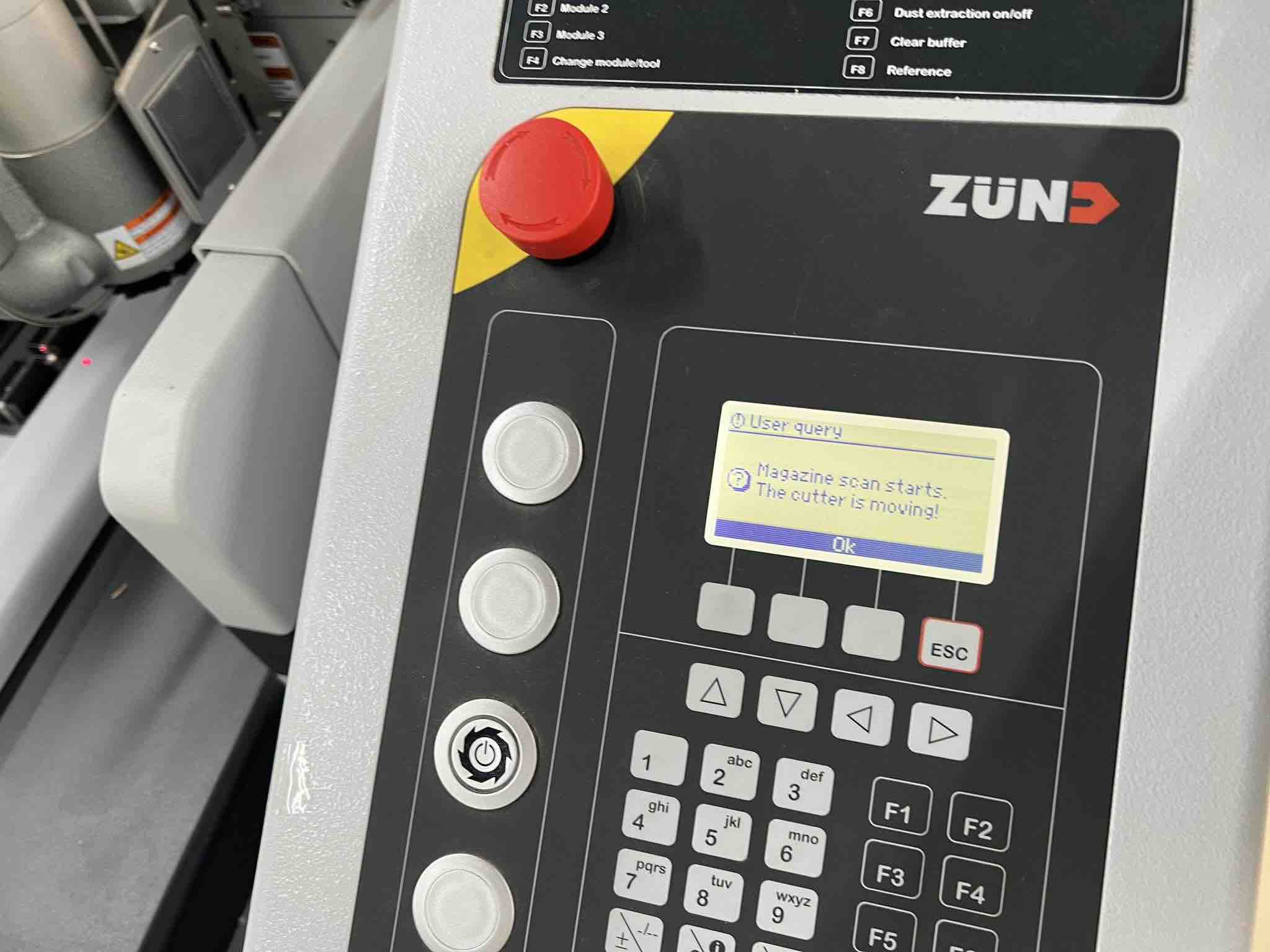
- The magazine will be scanned. The scan basically allows the machine to know what drill bits are in its magazine.
Design and Software
-
After completing the initialization of the machine and its tools, we will move on to the Zunds
PC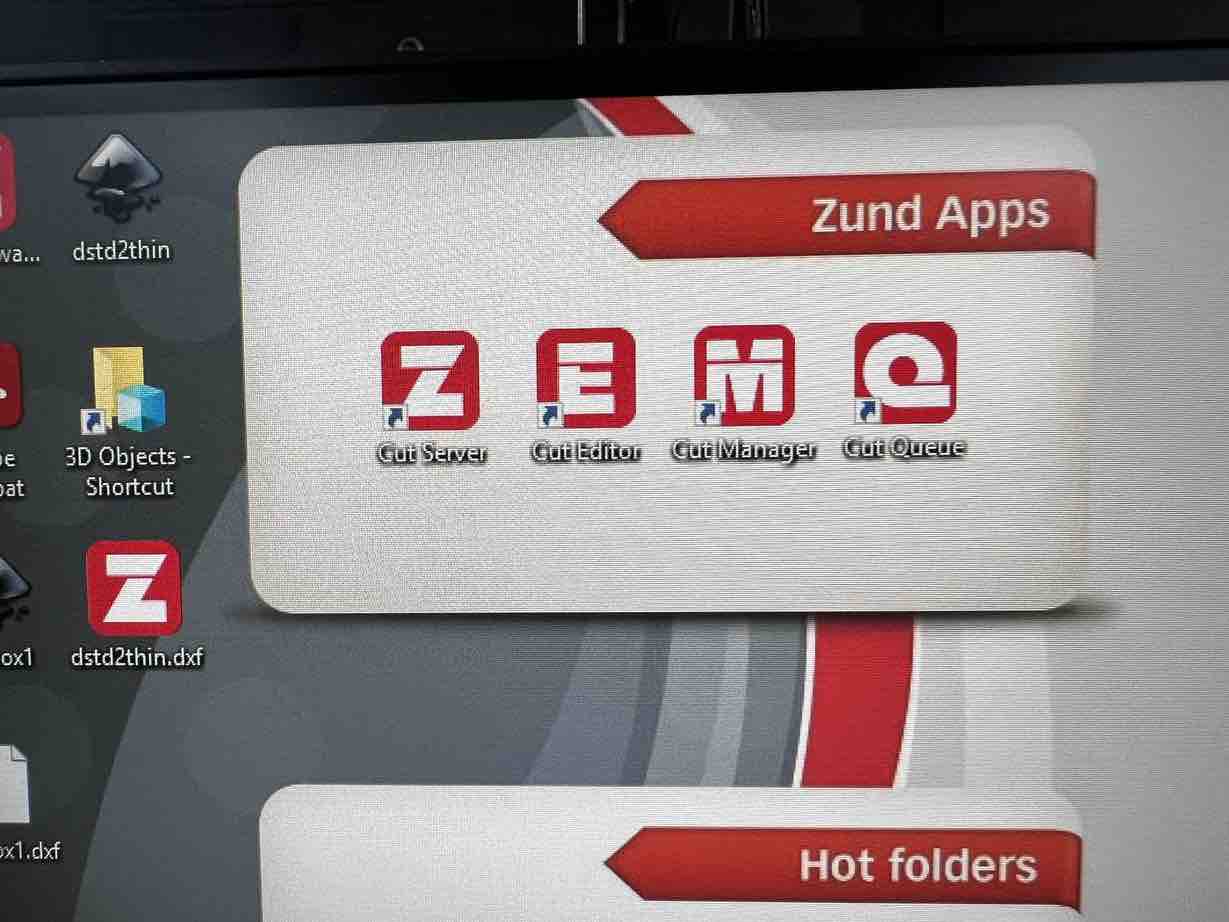
-
It has four main applications or
apps. Namely:a.
Cut Serverthis just connects the pc and machine to the same server so no need to touch thisb.
Cut EditorThis is where all the design editing, material selection and processes are assignedc.
Cut ManagerThis is where all the hardware, tools and material settings are stored. No need to touch this unless you want to add a new material that isn’t there already.d.
Cut QueueThis is where all your new and old jobs will be queued after finishing the settings in Cut Editor.e. not shown
Cut Centerthe final app where you assign the tool and bit you want to use to each process along with the tool’s functioning settings.
Cut Editor
- Begin with opening up
Cut Editor - From the top left, go to
file->importto import your design done in another app such as Fusion360 or Inkscape etc. Or you can design in cut editor itself but its not recommended.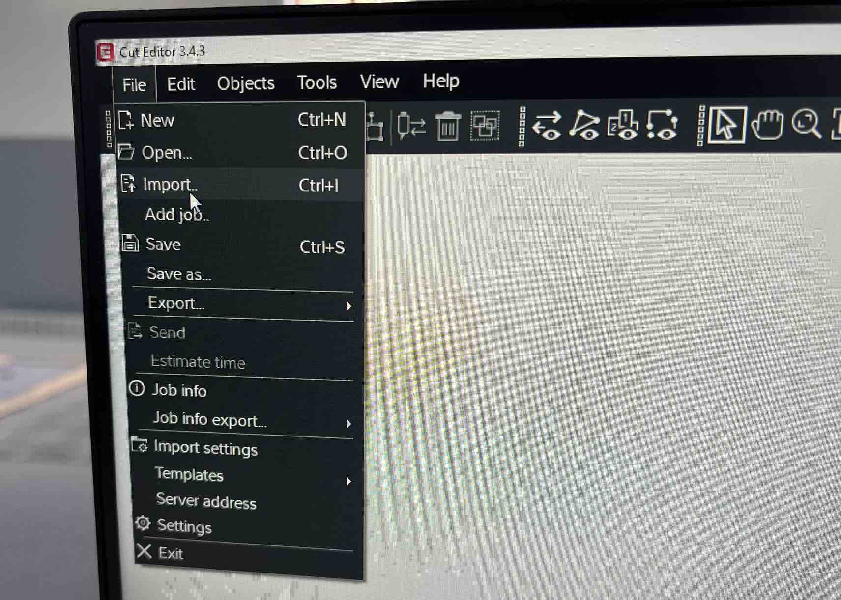
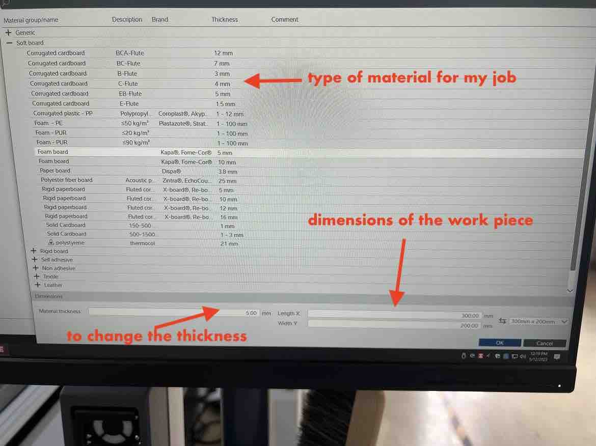
- On the top right, Select your
materialby clicking on the drawing icon next to thematerial taband assign its dimensions.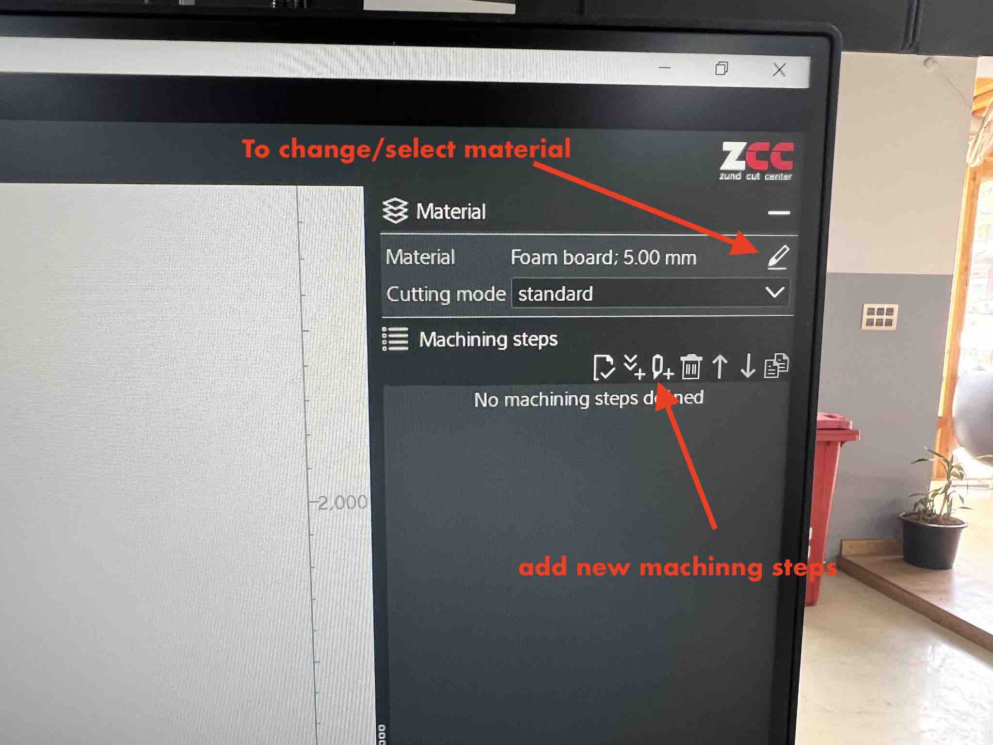
- Now to assign the process method, its as simple as selecting a line or lines on your design,
right-clicking, and then hittingNew MethodunderChange method. Once you already have a few methods set up, its as simple as right clicking and selecting the method. Once a method is added, it can be selected again and again so you will not need to “new method” for a same process.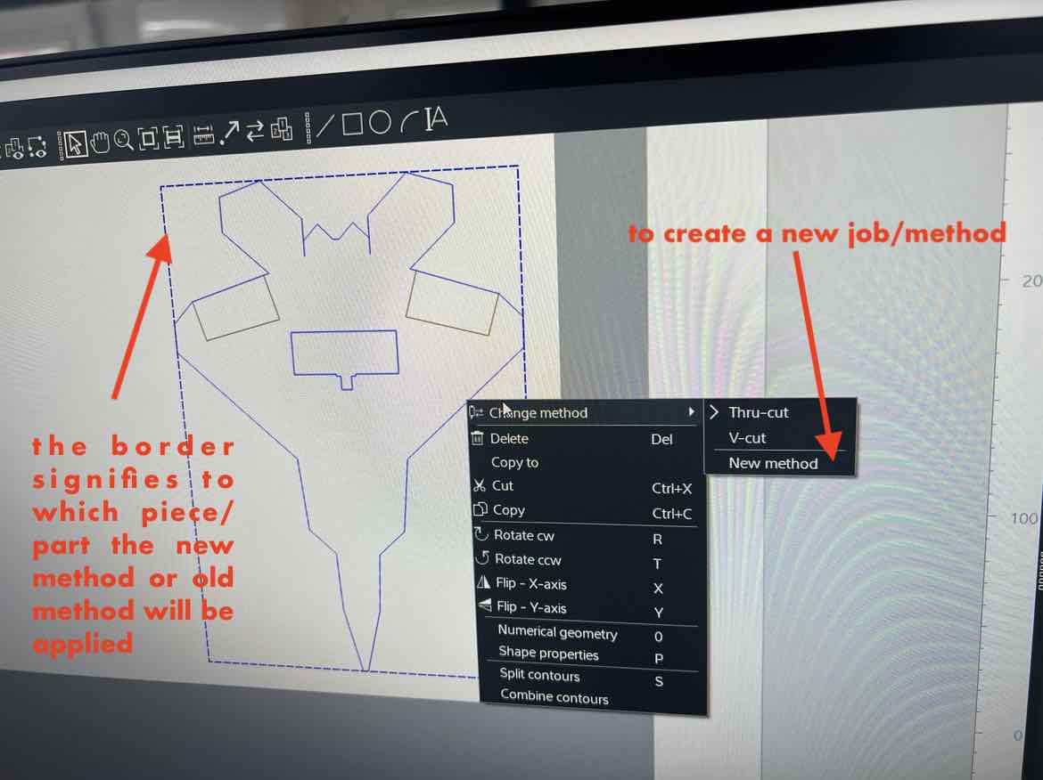
- There are many methods and again each method will differ for each material. In my case, I will use two cutting methods and one register method.
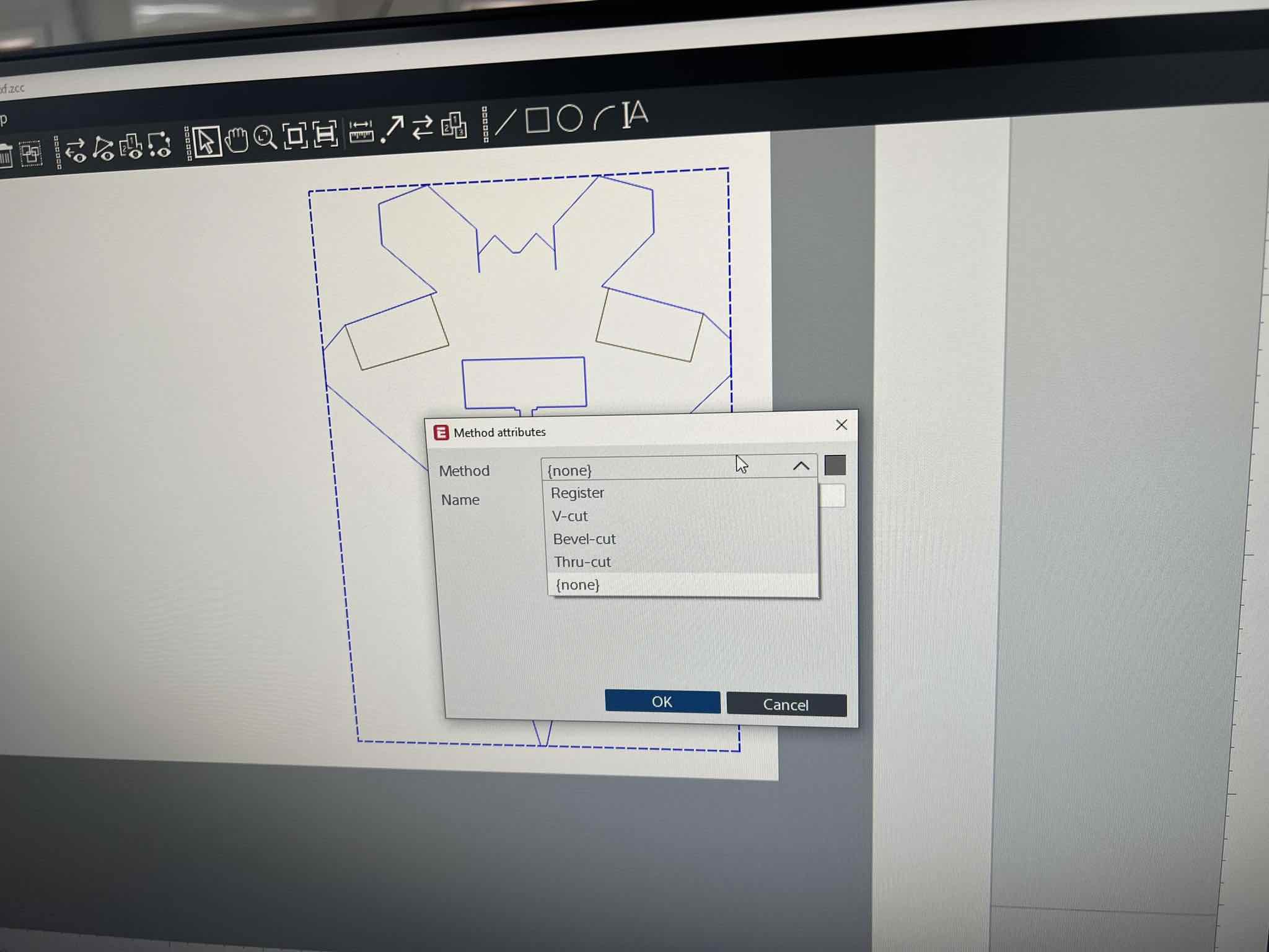
- Cut one is the
Thru-cutto cut out the shape of the F22, and as the name suggests, cuts through the material entirely. I select all the outer lines and lines I want to cut out in my design and assign them toThru-cut. - Cut two is the
V-cutwhich will cut the material at defined angles till a certain point, in order to make the material foldable. This method is used to make the ailerons and rudder moveable. I select the aileron and rudder lines and assign theV-cutto them.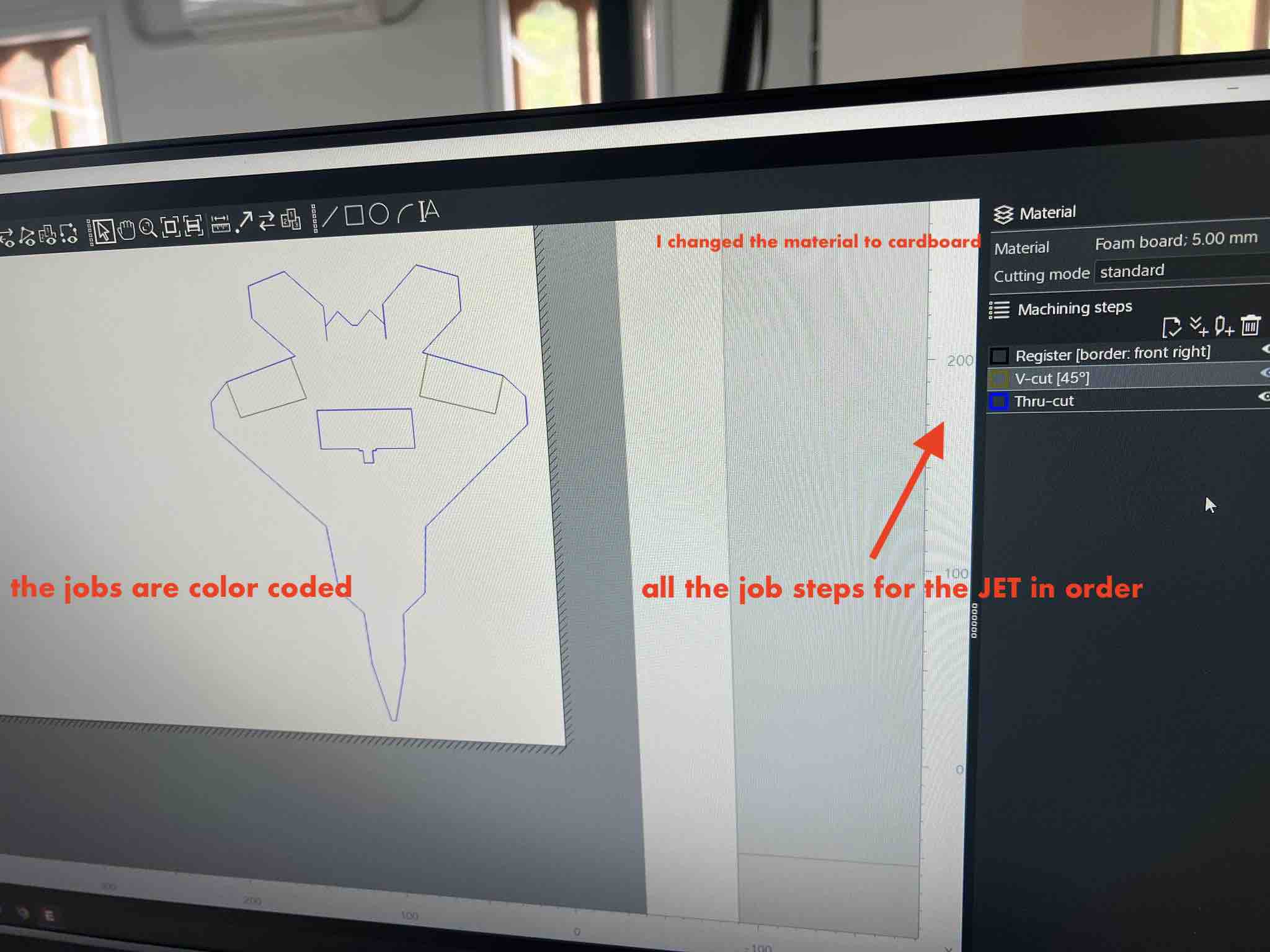
- Sometimes the lines of the design are all grouped up as one. This makes things difficult if you want to assign different job steps to different lines/parts in the same design. To split the lines, we need to
split contours. To do this, select the design you want to split,right-clickandsplit contours.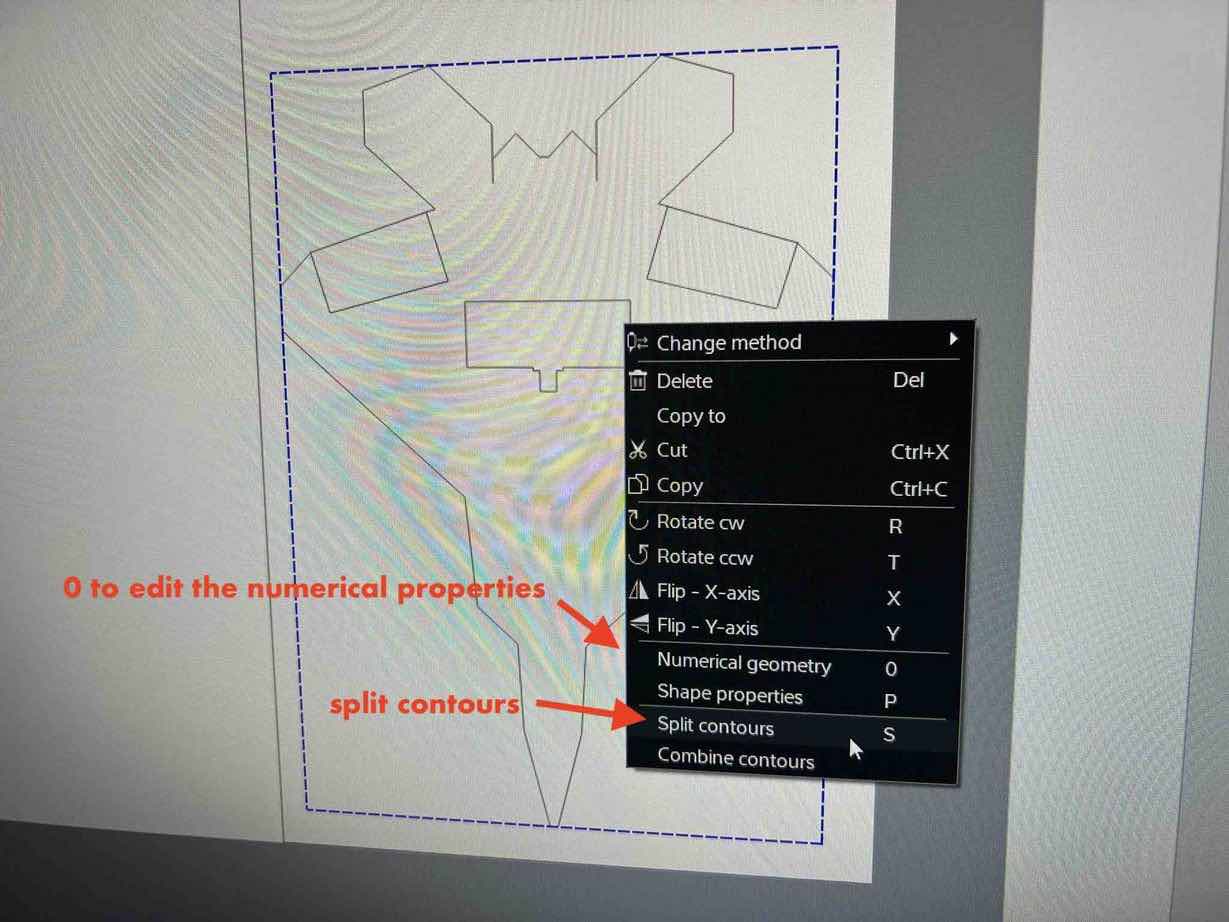
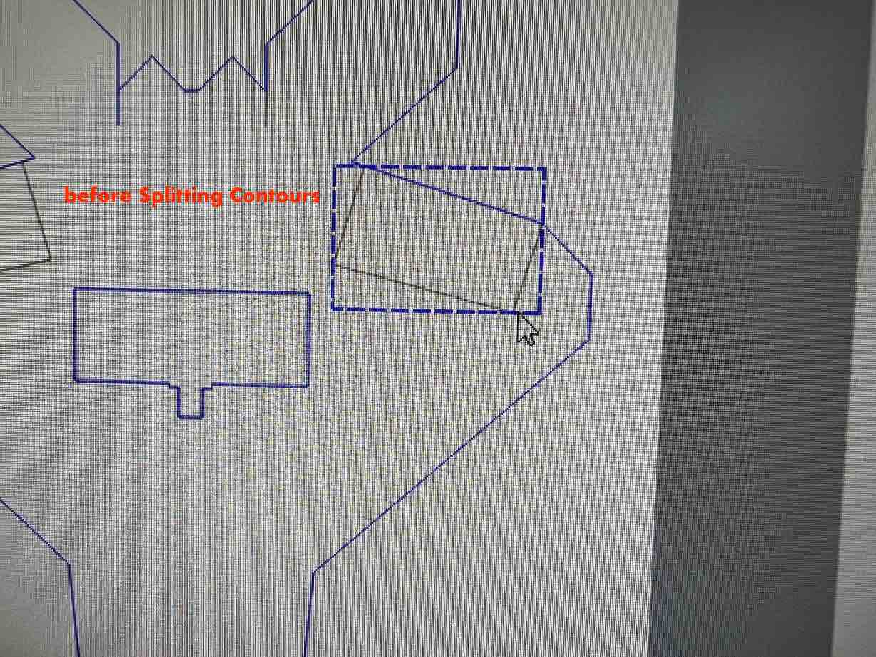
-
Example of splitting contours:
a.
b.
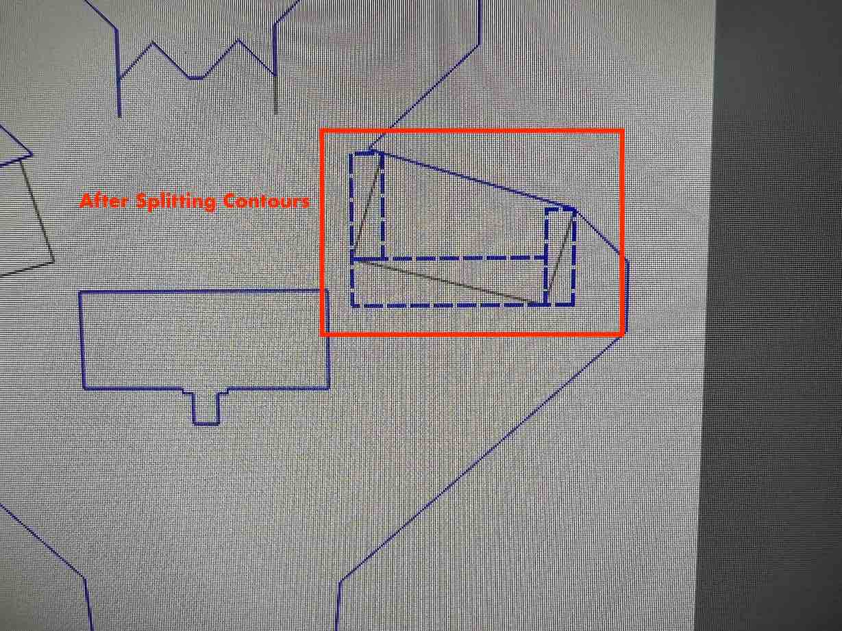
After splitting the contours, I can now easily assign separate V-cuts and thru-cuts to different lines in the same design. 1. Register is a process that utilizes the Zund’s camera to find points from where the cut will begin. I will use
Register: Front right Border, where in the camera will register the work piece’s right and bottom border and will use that as the reference points.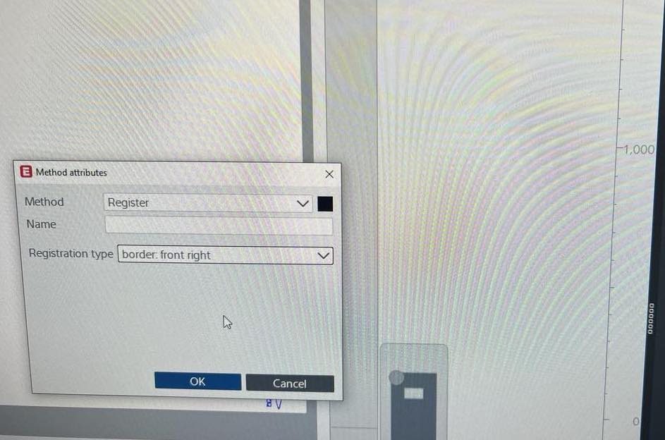 1. Theres another way to create/assign new methods. This can be done from under
 machining stepson the right hand side by clicking thetool icon. 1. Under Machining Steps, you an also reorder the processes by utilizing the arrows. It is necessary to move theregistermethod above the other methods to the top (the machine methods start from top to bottom), so that the camera will register the borders before beginning. 1.Move/Resize Rotate. Resizing, moving or rotating the design needs to be done in Cut Editor. To do this, select the design you want to modify and hit0. There you can move, resize or rotate your designs there.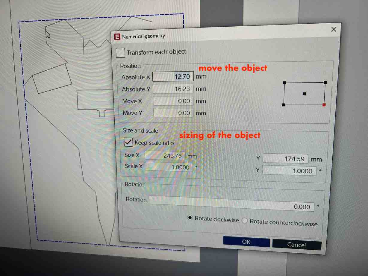 1. Once the:
a. material selection
b. process/method assignment
c. model editing
is done, on the top left hit the
send to servericon which looks like a letter doc with an arrow.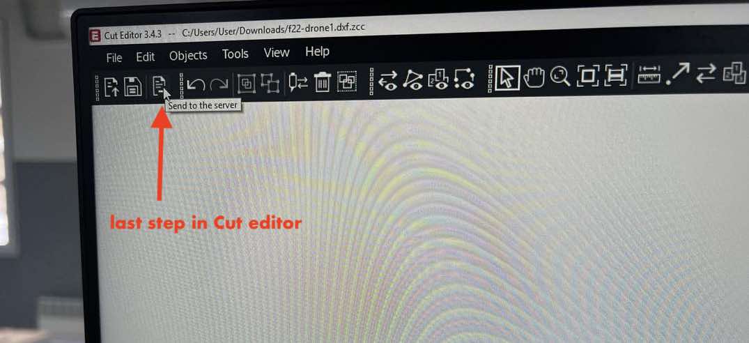 1. Your job will be saved and sent to the
 Cut Queue
Cut Queue
-
Find your job in the cut queue and double left click your job to open it in
Cut Center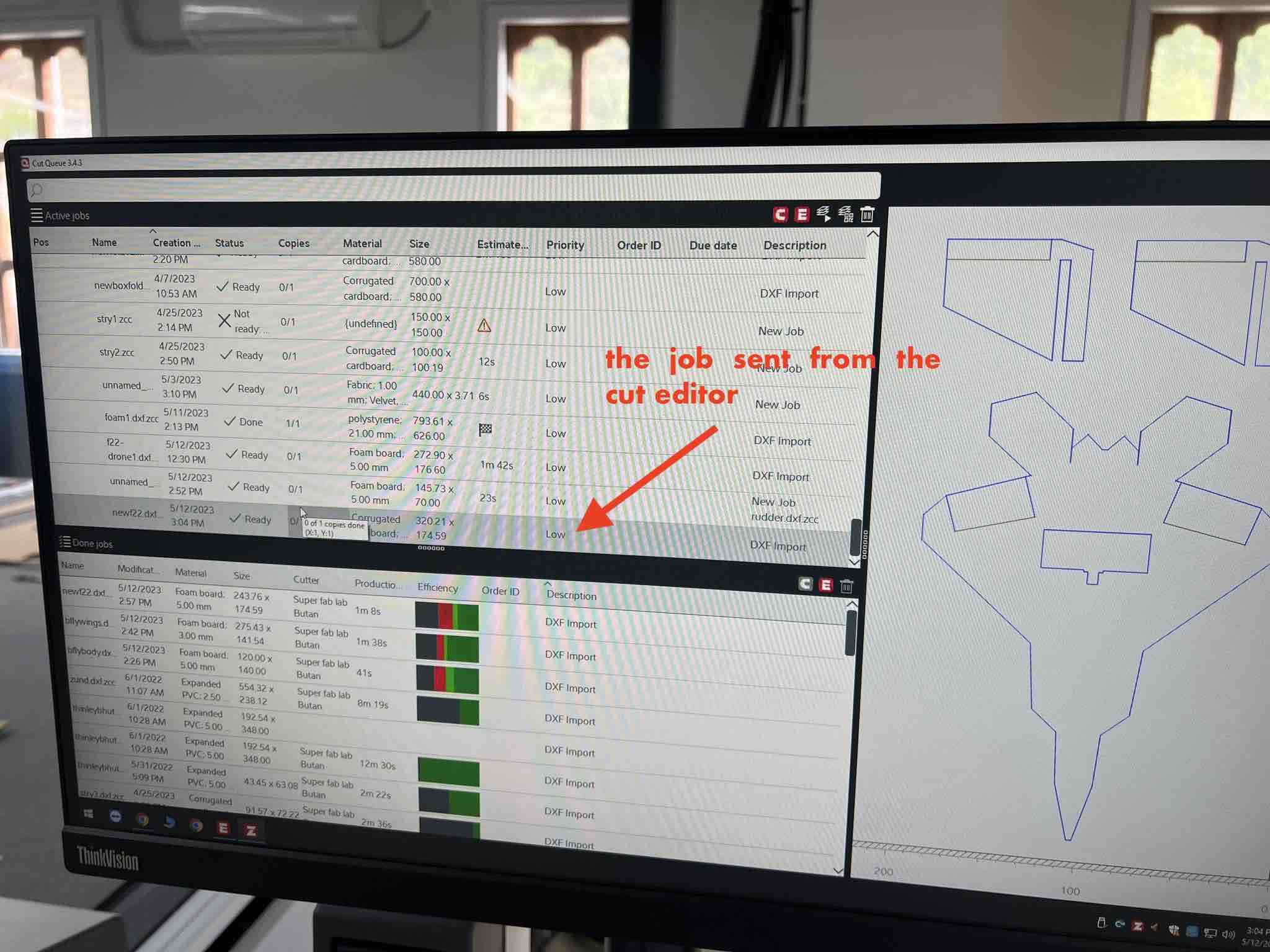
Cut Center
- with your job open, first thing is to check if the right tools are assigned to the right process. You can check this by clicking on the processes in the machining steps on the right.
- For V-Cut, everything is fine since we only have one V-cutting tool. only thing to be wary about here is the blade angle. Here you can also edit how deep you want the cut to be by editing the
base depth.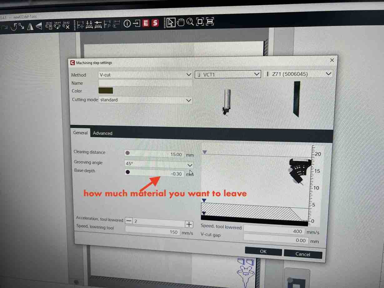
- For the Thru-cut however, we have many cutting tools and modules so its important to check that. We have the
UCTorUniversal Cutting Toolto cut simple, thin materials or soft materials like paper, foam board etc. We also have theEOTor theElectrical Oscillating Toolwhich is a motorized cutting tool for cutting thicker materials such as corrugated cardboard. Since I am working with Cardboard, I will use the EOT. One issue is that my machine currently has the UCT in module 1 and VCT in module 2 so I need to undergo atool changeprocedure to change the UCT to the EOT. - we will take a detour to tool change and will come back to Cut Center.
Tool Change
The modularity of the Zund makes changing tools very easy
1. On the machines’s operating screen, Hit F4 to initialize the tool change procedure
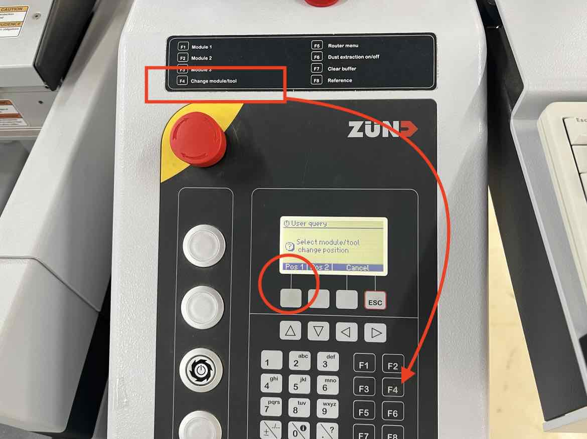 1. Upon hitting, f4, the modules will come towards you and the operating screen will prompt you to remove/change the tool. Selecting Pos 1 will bring the modules towards you, Pos 2 will take it to the back to where the ARC module is typically kept. DO NOT HIT OK until you are done changing the tool.
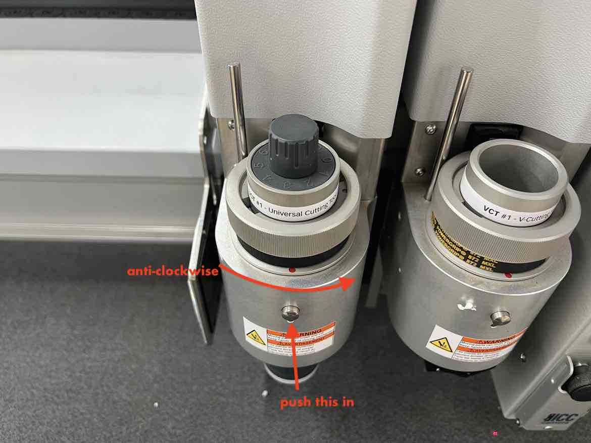
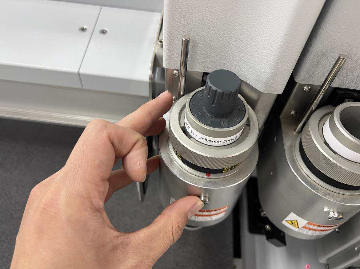
1. To remove the tool,
1. Upon hitting, f4, the modules will come towards you and the operating screen will prompt you to remove/change the tool. Selecting Pos 1 will bring the modules towards you, Pos 2 will take it to the back to where the ARC module is typically kept. DO NOT HIT OK until you are done changing the tool.
1. To remove the tool, press the circular button on the tool, and rotate the sleeve anti-clockwise. Once the red dot of the tool and the module sleeve are aligned, it is as easy as just pulling the tool out. In my case the UCT.
 1. Once the UCT (or prior tool) is removed, take the new tool (my case the EOT) you want to add and insert it into the module sleeve,
 aligning the red dot on the tool to the module sleeve
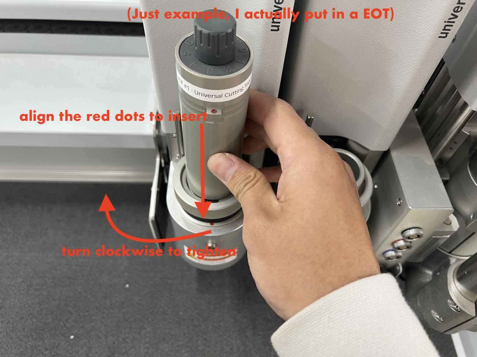 1. Once in, rotate the sleeve
 clockwise until hand tight.
1. (Extra step for the EOT: connect the power cable according to its color.The EOT has black tape on it so insert it into the black socket).
1. After the physical change is done, go back to the operating screen and hit ok
 1. Then, in the next screen, select the tool you added. In my case the EOT
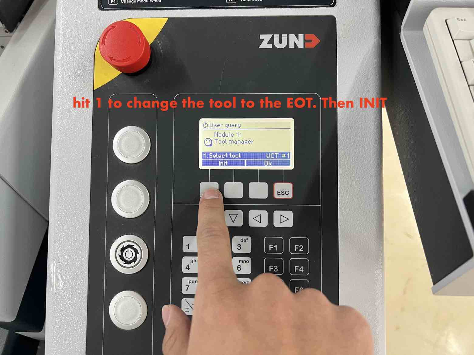 1. Then undergo the initialization process as done when starting up the machine.
here are the steps incase you forgot:

a. after selecting the Tool type
b. hit init
c. then hit ``2`` or ``auto init`` and then ``ok``
d. After the tool auto-initializes, hit ``ESC`` to save the settings
- Tool change complete, now back to the Cut center.
Back to CUT CENTER
- Now, select the Thru-cut job process and select the EOT device which was just replaced the UCT.
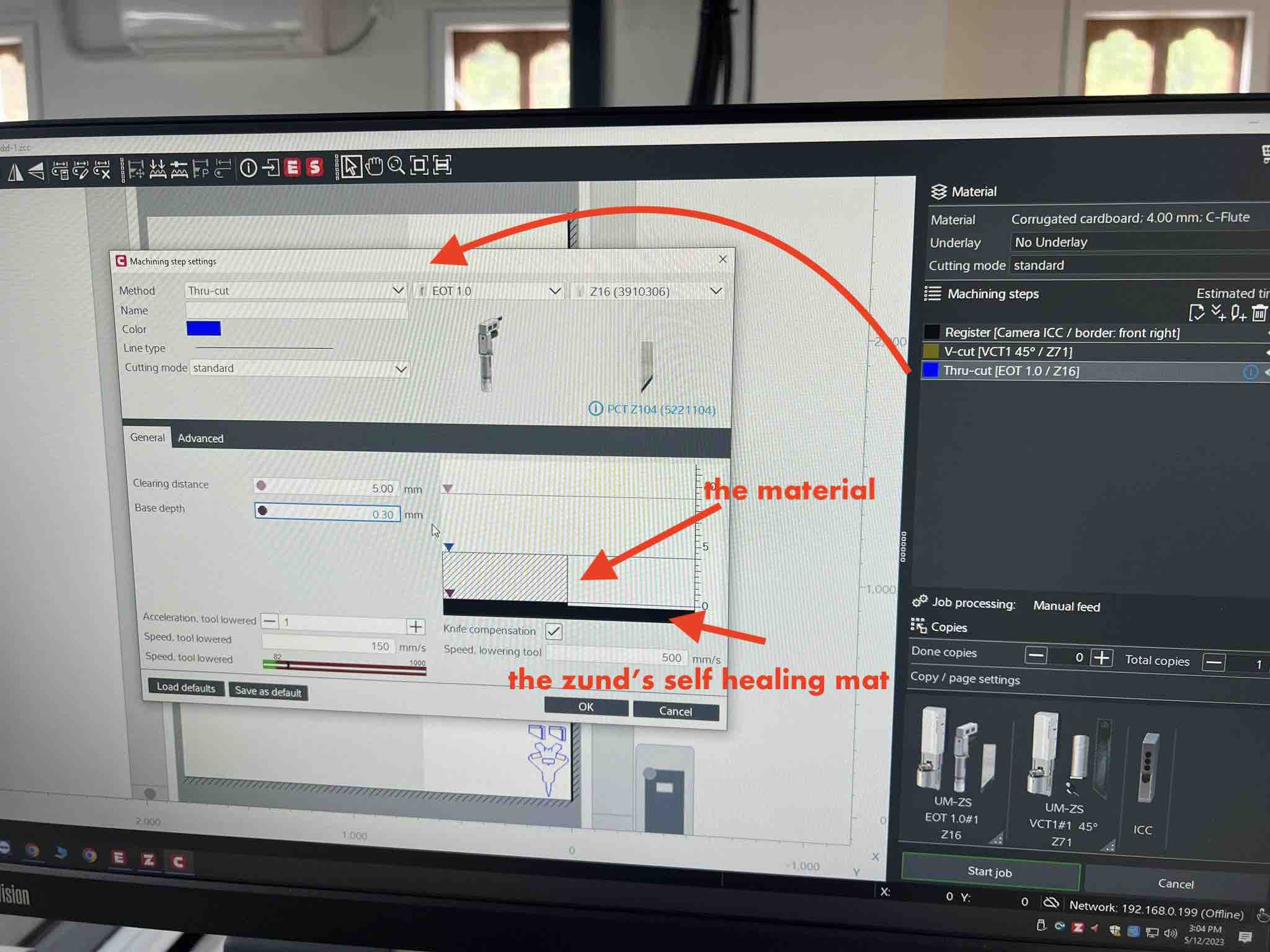
- You can edit base depth, clearing depth etc here.
- Once you check that the correct tools are selected for its respective job processes, you are almost close completing.
- The next important step is to go the operating keypad of the machine and hit
Online. This is a crucial step. If this isn’t done, you cannot send your job from the PC to the machine.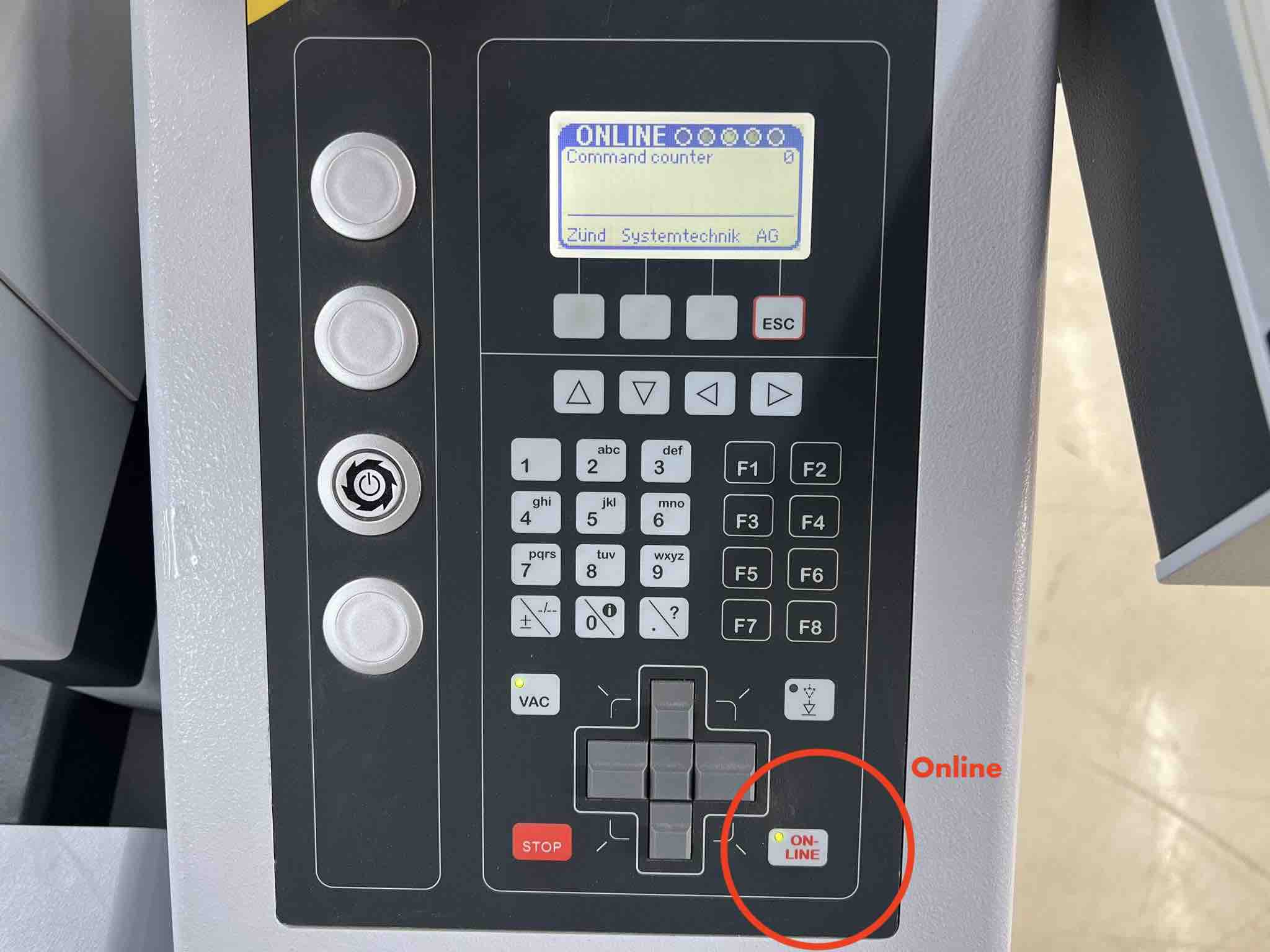
- Next turn on the Vacuum of the machine to hold the job piece down securely. After turning the vacuum on, place the job piece on the cutting area. In my case its a piece of cardboard.
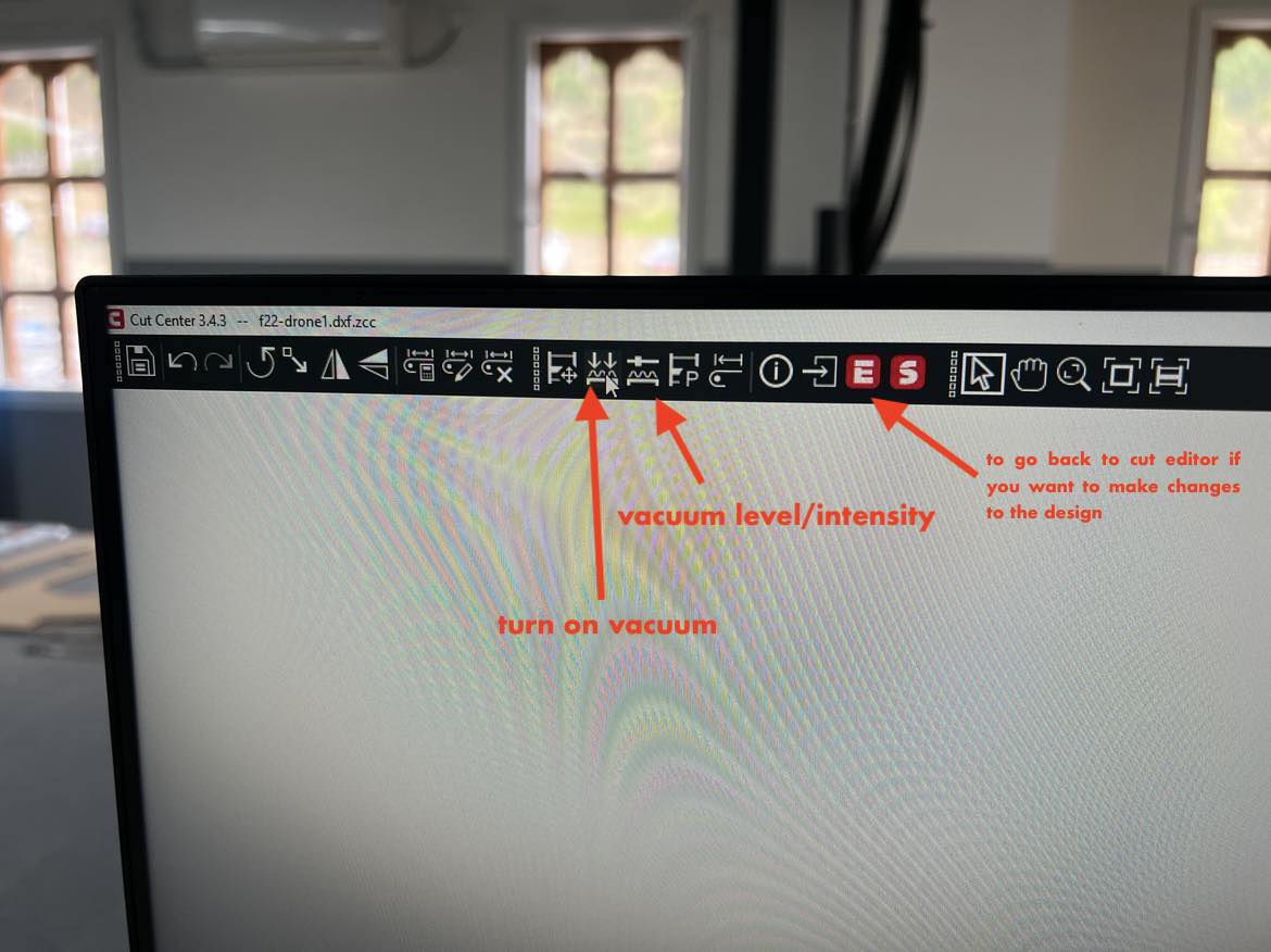
- Then in the Cut Center in the PC, Hit
Start Jobon the bottom right. If everything is good, this button will be surrounded by a green border. If theres some error, it will be surrounded by a orange border and the machine will tell you whats wrong.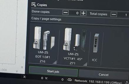
- After hitting
start job, the ``register process will begin. Utilize the pc’s arrow keys to align the camera with the right border first and hit Enter. Then align it with the bottom border and hit enter. This will Register the borders after which your Job will begin.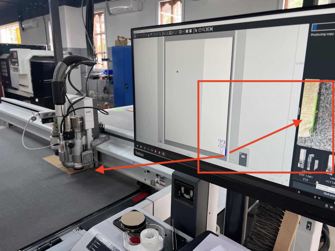
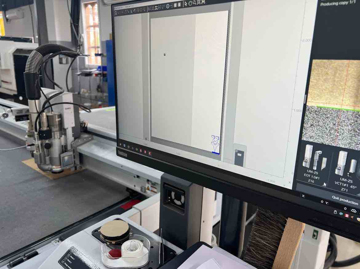
- You can see the Job completion ETA on the PC while the machine undergoes the job.
The cutting:
Post Cut:
After the cut:
Final Hero:
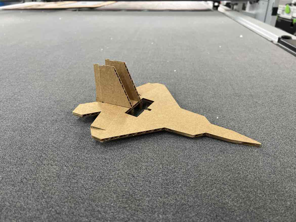
Aileron Folding due to the V-CUT:
Rudder Folding due to the V-cut:
Design Files:
DXF of the Plane:F22 dxf
DXF of the Rudder: Rudder dxf
f3d files: f22 f3d
zund job file: zcc file