Week 4. Embedded Programming
This week we finally stepped into the more “serious” portion of Fabacademy. As a mechanical engineer with very minimal knowledge of electronics, I actually felt very nervous through out the entire lecture as there were words and terms that I either didn’t understand or ever heard before.
However, after beginning the hands-on portion for the week, I felt a bit better and I actually had fun learning new things.
Group Assignment:
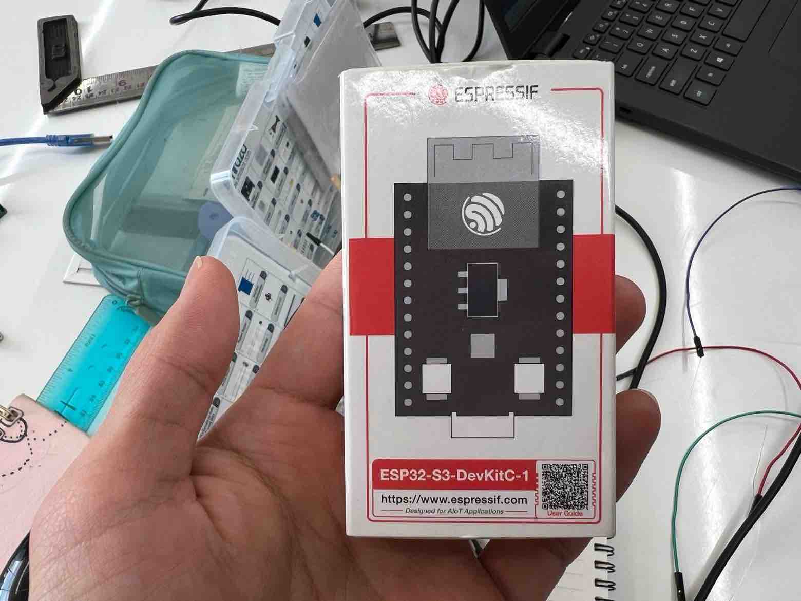
Unfortunately, we only had developer kits for the Arduino Uno/Mega and the ESP32 in the lab so we were able to only compare the two.
Link to the Group Assignment:
It was a great experience especially since I was messing around with an Arduino after many years and was dealing with an ESP32 for the first time. We used the Arduino IDE for both so the workflow was almost identical apart from putting it together. I personally prefer the arduino Uno over the ESP especially as a beginner, it just feels more user friendly.
Arduino
As a novice, it was very interesting to learn that Arduino is more than just a board but is also a toolchain, libraries, Integrated Development Environment, bootloader and Header programming.
An IDE is the software application wherein we can work on our code. It typically consists of a code editor and a debugger.
Arduino IDE is my IDE of choice and will be using it for my Fabacademy Journey.
The Arduino Reference is a great useful resource for anything and everything Arduino
Setting up Arduino IDE
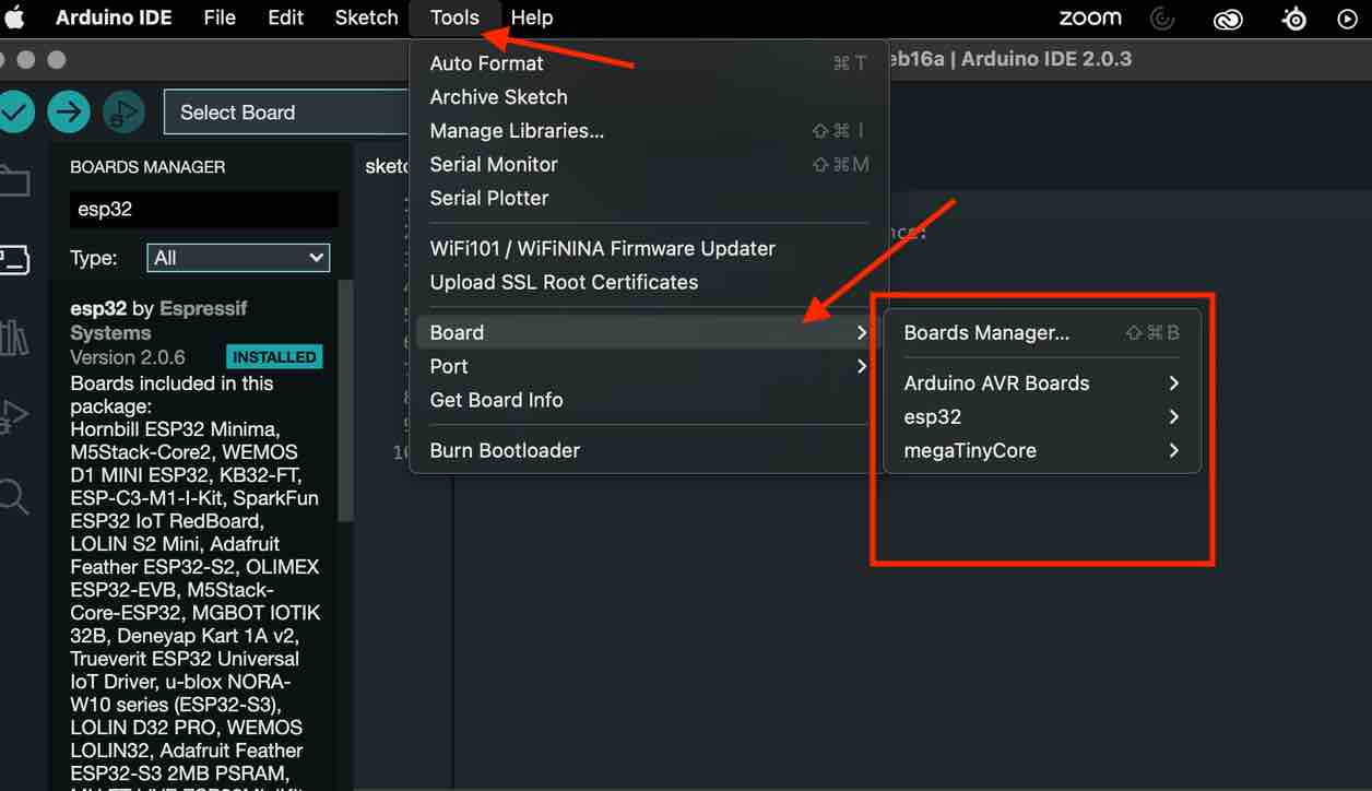
After downloading it, I first ensured to download the various boards that we would be using. The typical workflow for installing a different board would be:
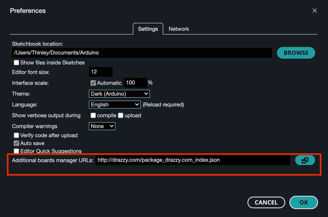
1. Go to preferences
-
add the URL of the additional board
-
Go to
tools->board manager -
Download and Install the new board
I first began with downloading and installing the Arduino AVR package and this was prebuilt into the IDE so I didn’t have to add a new URL. I then wanted to download board libraries for the the megaTinyCore and the ESP 32.
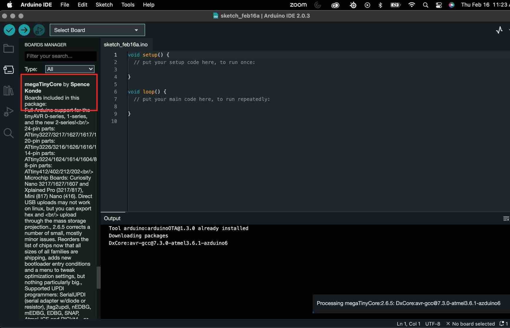
For the megaTinyCore, I input the URL (which can be found in the linked git): http://drazzy.com/package_drazzy.com_index.json to the additional board manager URLs (in preferences). Then from tools->board manger-> I downloaded and installed megaTinyCore.
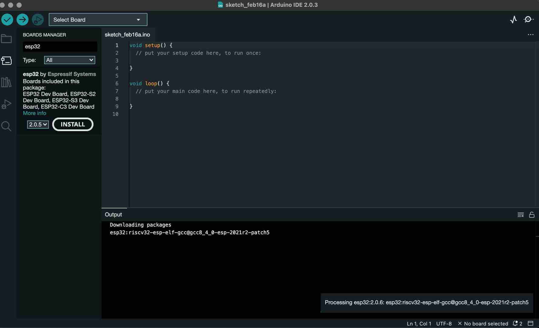
Next for the ESP 32, I added the following URL to the additional board manager URLs: https://raw.githubusercontent.com/espressif/arduino-esp32/gh-pages/package_esp32_index.json, then downloaded the esp32 by espressif systems from the board managers.
I was happy with these three board libraries and went on to work on the actual arduino.
Arduino Uno
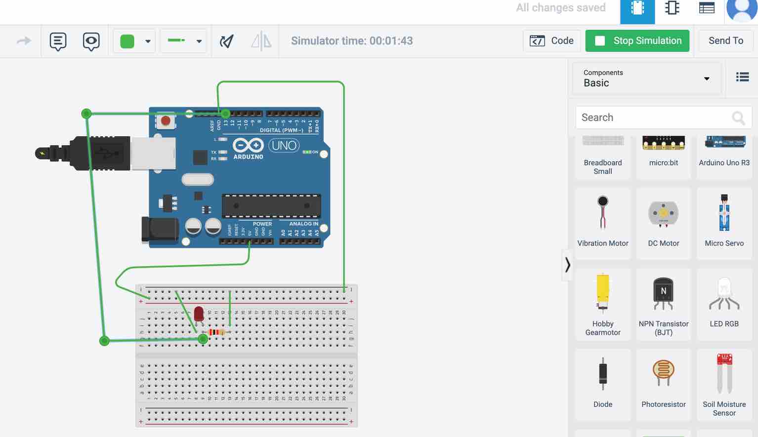
Its been a while since I last used an Arduino so I wasn’t feeling confident. To get over that hurdle, I first began messing around in TinkerCAD circuits which is a really user friendly yet powerful tool for circuit programming. It has a wide range of components and gives you the option of simulating your board to see of the connections/code works. It also has code in the form of “blocks” for which you just have to use logic and they generate the code based on that.
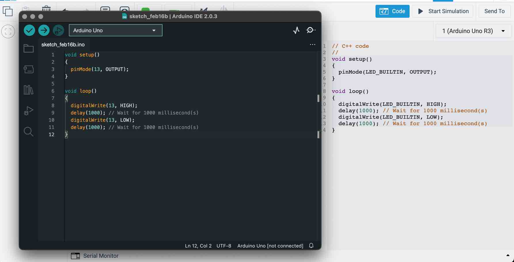
First, I modelled a simple uno board with an LED and wanted it to blink. Once I had set up the model and simulated the model in TinkerCAD, I copied that code pasted it in the Arduino IDE, and then began replicating the model in person.
Everything was going well. I debugged the code, selected arduino Uno as my board, selected theport which was connected to the uno from my laptop’s USB port, selected the programmer to be Arduino as ISP and sent the code to the Uno.
It didn’t work and I got the following error:
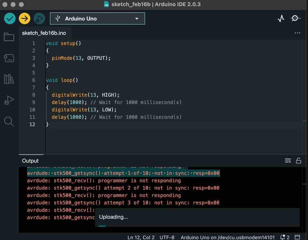
I tried everything like rewiring, checking the code, changing the components but it still wouldn’t work, so I tried using Rinchen’s Uno and it worked, so it turns out that my uno was faulty. After diagnosing that, I got an Arduino Mega and ran the same, selecting the board to be an Arduino Mega or Mega 2560 and it worked.
This was the code I got from TinkerCAD that I used on my Mega:
After this, I added two more LEDS to the board and wanted to make it so that the LEDS will blink one after the other. I edited and used the following code and it worked:
void setup()
{
  pinMode(13, OUTPUT);
  pinMode(12, OUTPUT);
  pinMode(11, OUTPUT);
}
void loop()
{
  digitalWrite(13, HIGH);
  delay(2000); // Wait for 2000 millisecond(s)
  digitalWrite(13, LOW);
  digitalWrite(12, HIGH);
  delay(2000); // Wait for 2000 millisecond(s)
  digitalWrite(12, LOW);
  digitalWrite(11, HIGH);
  delay(2000); // Wait for 2000 millisecond(s)
  digitalWrite(11, LOW);
}
I felt a lot better about myself and then moved onto tackling the Individual Assignment (I read the data sheet prior to doing all this but wanted to keep the individual assignments together for ease of reading for the evaluators)
Individual Assignment
Datasheet
Since I will mainly be working on an Arduino Mega in the beginning I decided to look into the datasheets for the ATmega2560 and more specifically one for the Arduino Mega 2560 which is based on the ATmega2560.
The ATmega2560 is a very powerful microchip 8-bit AVR RISC-based microcontroller with low power. It operates at a frequency of 16 MHz (clock speed), achieving a throughput of 16 MIPS (million instructions per second) at 16 MHz. Since the device is able to achieve 1 MIPS per 1 MHz, it has a good balance of power consumption and processing speed. As for memory it has a combination of 256 KB of flash memory, 8 KB of SRAM(static random-access memory) and 4 KB of EEPROM (a memory that is not erased when powered off!). It has a max operation voltage of 5.5V and a min operation voltage of 1.8, with a total pin count of a 100.
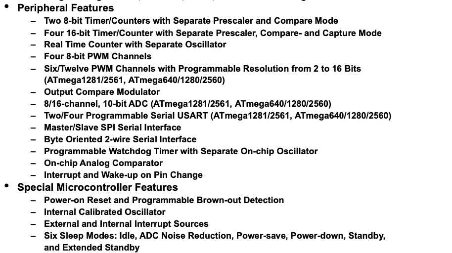
Some of it’s Peripheral and Special Features:
The Pin-out diagram of the ATMEGA2560:

The Arduino Mega is just a Microcontroller dev board that is based on the ATMega2560 so the tech specs are almost identical. The Arduino Mega is really useful in robotics. I just wanted to include it since I am working on the Arduino Mega and the Pin-out diagram is very helpful:
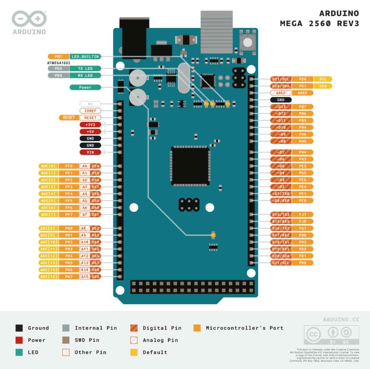
The Arduino Mega has 13 Built-in LED pins, 54 Digital I/O pins, 16 Analog Pins and 15 PWM pins. The Mega has four hardware serial ports (UARTs) to connect to several devices. Along with the 4 UARTs communications, it can also communicate through I2C and SPI
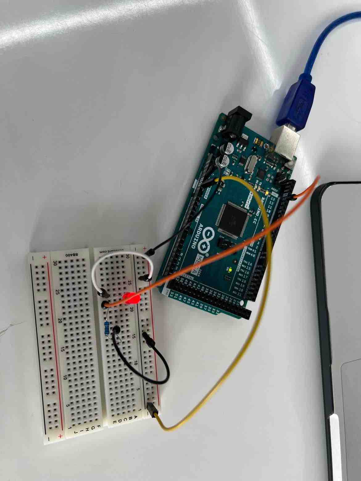
LED control from Serial Monitor
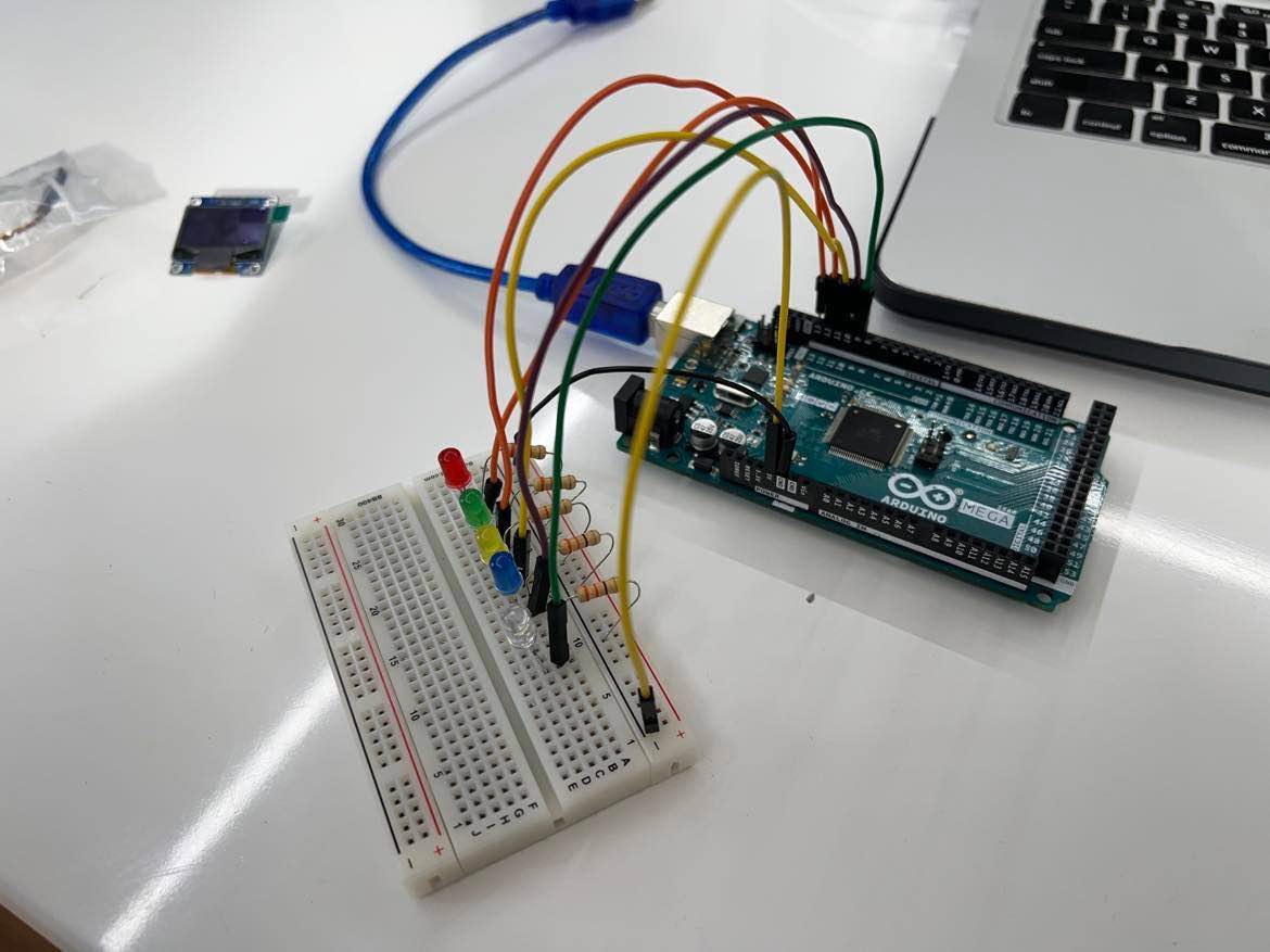
For this weeks assignment, I set up a board with 5 LEDS (initially just 3), which can be controlled from arduino’s serial monitor. I had the red led connected to Serial input 1,green led connected to Serial input 2, yellow led connected to Serial input 3, blue led connected to Serial input 4, white led connected to Serial input 5. Any input above 5, would return a message saying “Please select a number from 1-5”.
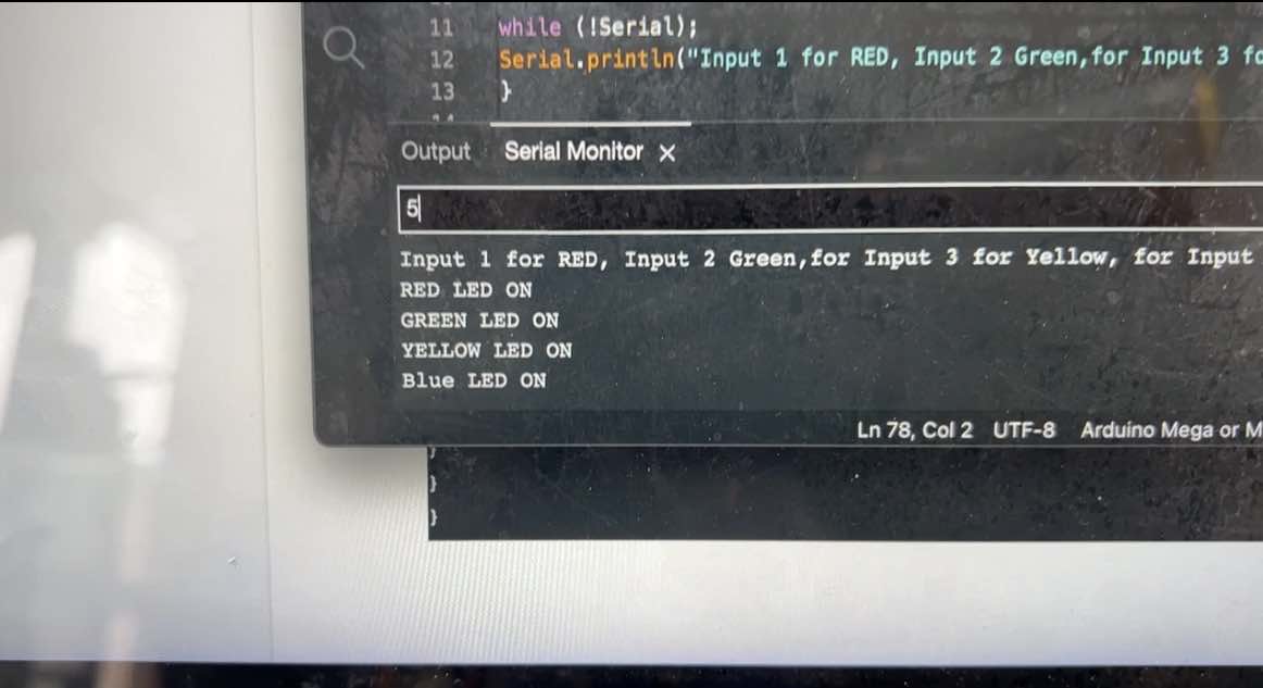
Basically the code works as following: Once the code begins, the serial monitor will prompt the user asking for a number with the attached color. If I type 1 in the serial monitor, then the red led will light up until another option is selected, and the serial monitor will also out put a message saying “RED LED ON”. This being the same for the colors coded 1-5.
The serial monitor after entering 1-4:
The initial reference for the code: serial to led
The Code I used:
 void setup()


{
pinMode(13, OUTPUT);
pinMode(12, OUTPUT);
pinMode(11, OUTPUT);
pinMode(10, OUTPUT);
pinMode(9, OUTPUT);
Serial.begin(9600);


while (!Serial);
Serial.println("Input 1 for RED, Input 2 Green,for Input 3 for Yellow, for Input 4 for Blue, for Input 5 for White");
}

void loop() {
if (Serial.available())
{
int state = Serial.parseInt();

if (state == 1)
{

digitalWrite(13, HIGH);
Serial.println("RED LED ON");
digitalWrite(12, LOW);
digitalWrite(11, LOW);
digitalWrite(10, LOW);
digitalWrite(9, LOW);
}

if (state == 2)

{

digitalWrite(12, HIGH);
Serial.println("GREEN LED ON");
digitalWrite(13, LOW);
digitalWrite(11, LOW);
digitalWrite(10, LOW);
digitalWrite(9, LOW);
}
if (state == 3)
{

digitalWrite(11, HIGH);
Serial.println("YELLOW LED ON");
digitalWrite(12, LOW);
digitalWrite(13, LOW);
digitalWrite(10, LOW);
digitalWrite(9, LOW);
}
if (state == 4)
{

digitalWrite(10, HIGH);
Serial.println("Blue LED ON");
digitalWrite(12, LOW);
digitalWrite(11, LOW);
digitalWrite(13, LOW);
digitalWrite(9, LOW);

}
if (state == 5)
{

digitalWrite(9, HIGH);
Serial.println("WHITE LED ON");
digitalWrite(12, LOW);
digitalWrite(11, LOW);
digitalWrite(10, LOW);
digitalWrite(13, LOW);
}
else
{
 Serial.println("Please select a number from 1-5
");
 digitalWrite(9, LOW);
digitalWrite(12, LOW);
digitalWrite(11, LOW);
digitalWrite(10, LOW);
digitalWrite(13, LOW);
}
}
}
Extra: Servo motor
Since my final project revolves around a fixed wing drone, I wanted to explore controlling a servo motor using the arduino mega. I connected the servo to the arduino following the following schematic:
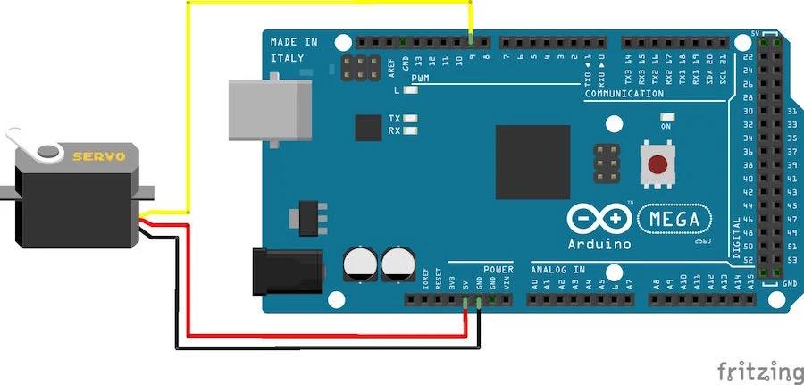
and then I used the servo sweep program found here. Since I was just trying it out for the first time, I did not edit the code.
I successfully sent the code to the arduino and it worked!