Week 8. Electronics Production
Group Assignment
Some points:
- When loosening the bit during z axis adjustment, hold the bit so it doesn’t fall
- Don’t tighten the bit too hard. It will be harder to remove and will also damage the bit
- Try to never use the
go to z origin. You run the risk of breaking the bit (it may drop down hard). - Check continuity after milling and after soldering
Individual Assignment
Heroshot:
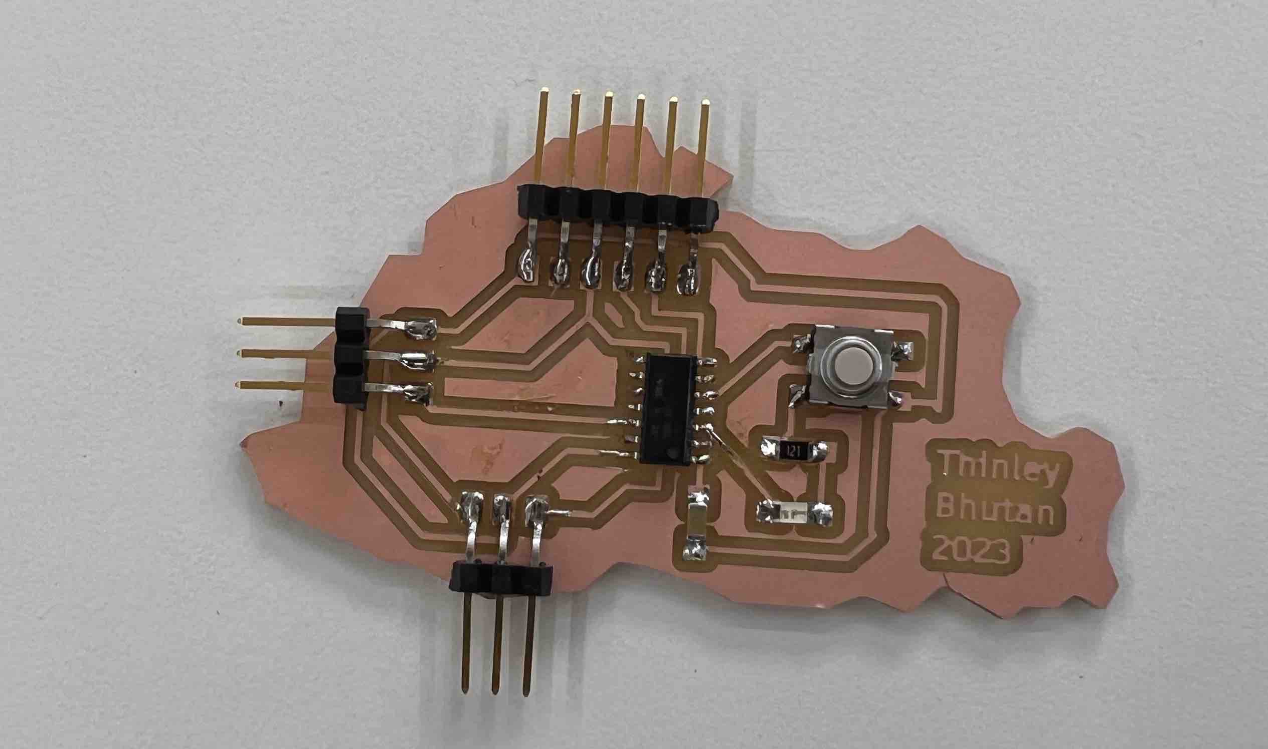
For this week, I wanted to produce the board I designed during the electronics design week!
I already had all my pngs ready so the next step would be to use MODS.
MODS
To go from png to an rml that can be fed into the ROLAND SRM20, MODS is used.
Workflow for MODS:
-
Open google chrome and search [MODS]https://mods.cba.mit.edu/ or
https://mods.cba.mit.edu/ -
Once there, right click, go to
programs->open server program-> underROLAND->SRM20->PCB png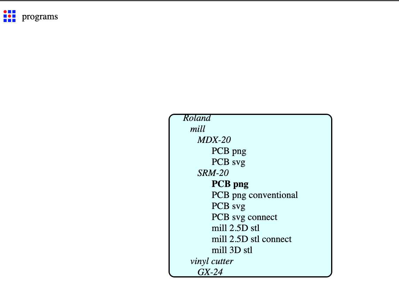
-
Then the ROLAND SRM 20 program should pop up.
traces:
-
In the first node on the left
insert your traces png. for me it wasThinleyEDtraces.png`` -
In the node underneath that titled “Roland SRM20 milling machine”, set the
x,yandzaxis to0mm. -
delete the node next to that titled “Websocket device”. Then
rightclick->module->server module->file->save. Then connect the output files of the Roland SRM20 milling machine to the input files of thesave file -
Under the
set PCB defaultsnode, selectmill traces 1/64since we are going to mill the traces first. -
Finally, under
mill 2D rasterselectcalculate. your rml file will be saved and you can view the milling path.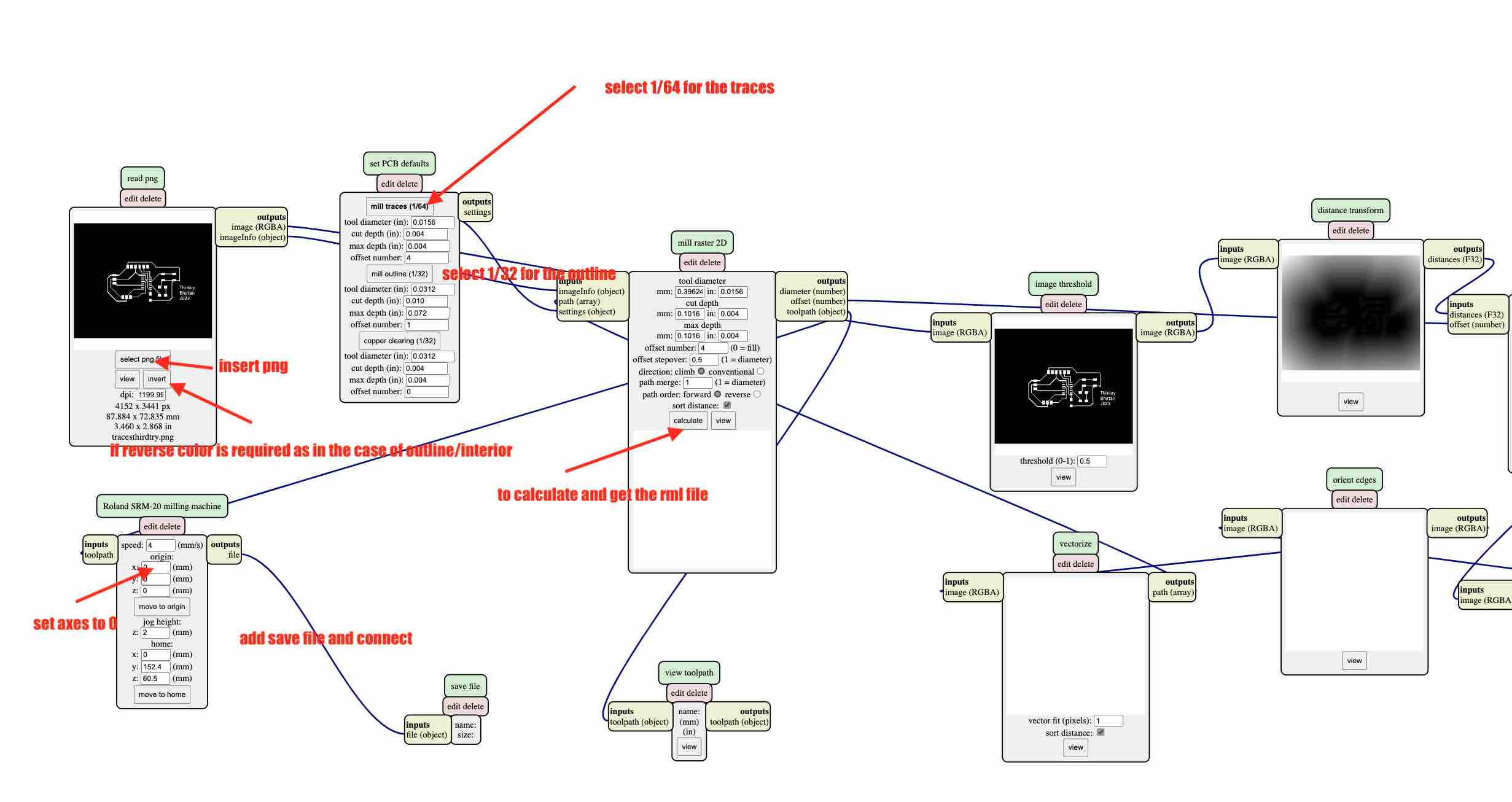
Outline
-
In the first node on the left
insert your traces png. for me it wasThinleyEDint.png`` -
In the node underneath that titled “Roland SRM20 milling machine”, set the
x,yandzaxis to0mm. -
delete the node next to that titled “Websocket device”. Then
rightclick->module->server module->file->save. Then connect the output files of the Roland SRM20 milling machine to the input files of thesave file -
Under the
set PCB defaultsnode, selectmill traces 1/32since we are going to mill outline of the board first. -
Finally, under
mill 2D rasterselectcalculate. your rml file will be saved and you can view the milling path.
Roland SRM20 and VPanel for ROLAND SRM20
With the RML’s done, we need to move onto the machine and it’s job center called Vpanel
Workflow:
-
Turn on the machine by hitting the power button. Ensure to have the front lid closed.
-
Open Vpanel on the computer connected to the machine.
-
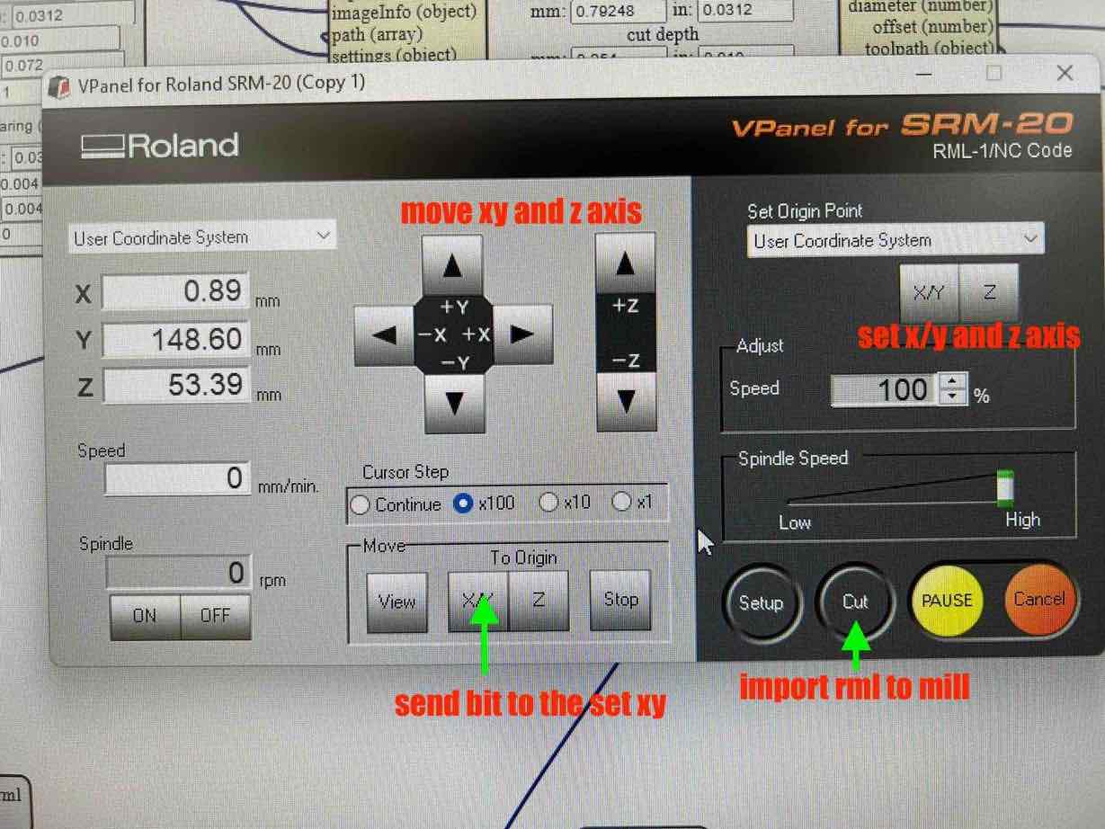
control the
keypadand set your bit over where you want the xy origin to be set. once you are happy with the position, hitX/Yunder theSet origin pointto set that location as your X/Y origin.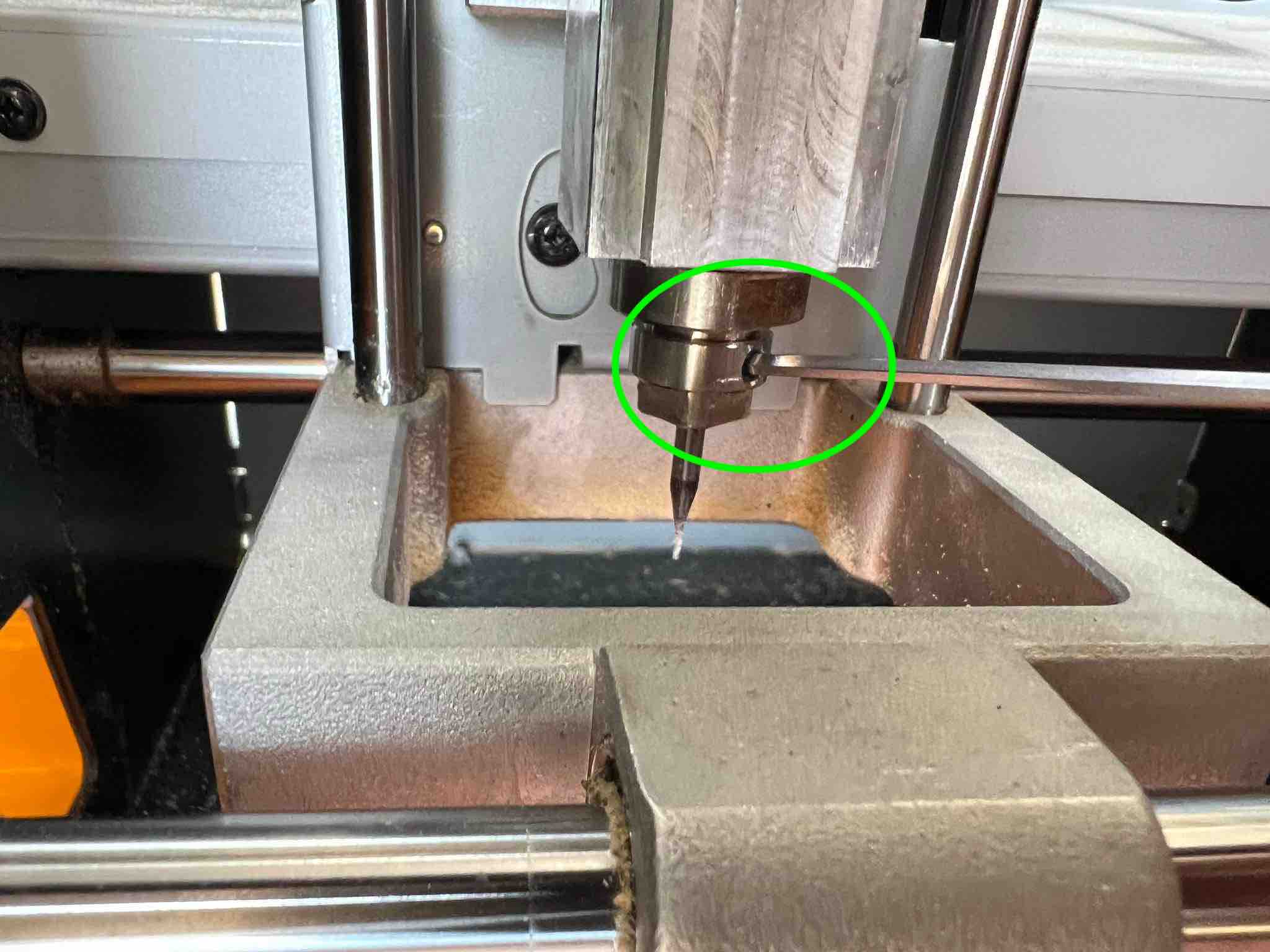
-
Open the lid, then lower your z axis ever so slowly until its almost about ti touch the bed. Then take the allen key and loosen the bit, doing this while holding the bit with your other hand. Once the bit is loosened, slowly drop it till it touches the bed. Then hold the bit and re-tighten it. Hit the
Zunder theSet origin pointto set that location as Z origin. (Assuming the 1/64 bit is already inserted)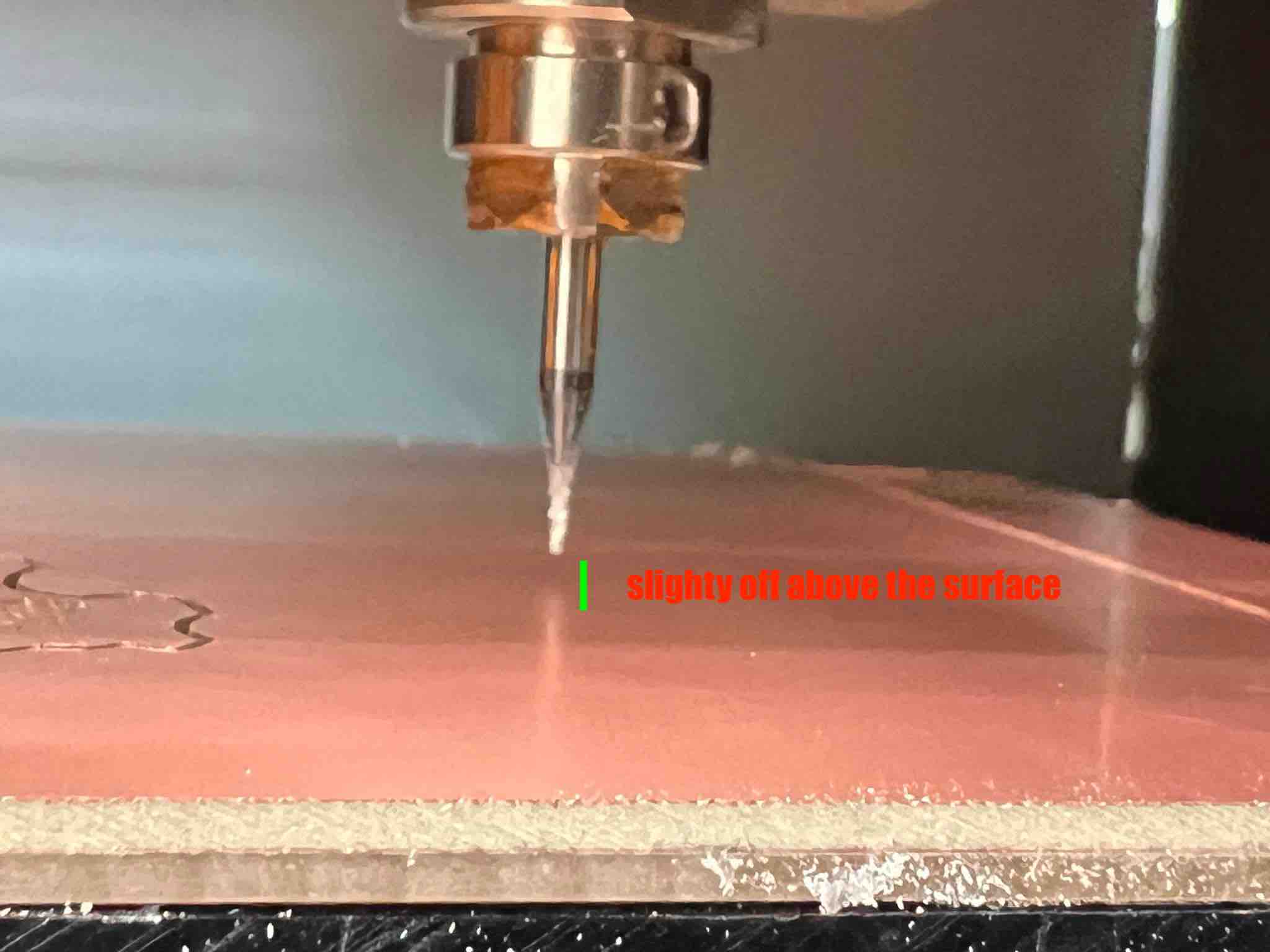
-
On the left had side, set your
cursor steptox100and tap the+zjust once to ensure 1 mm of positive z moment. then close the lid. -
Now you are ready to mill. Select
cuton the right hand side of vpanel andaddyour traces rml file. HitOutputand the cut will begin.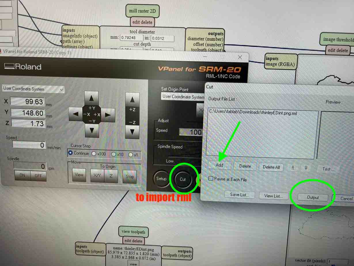
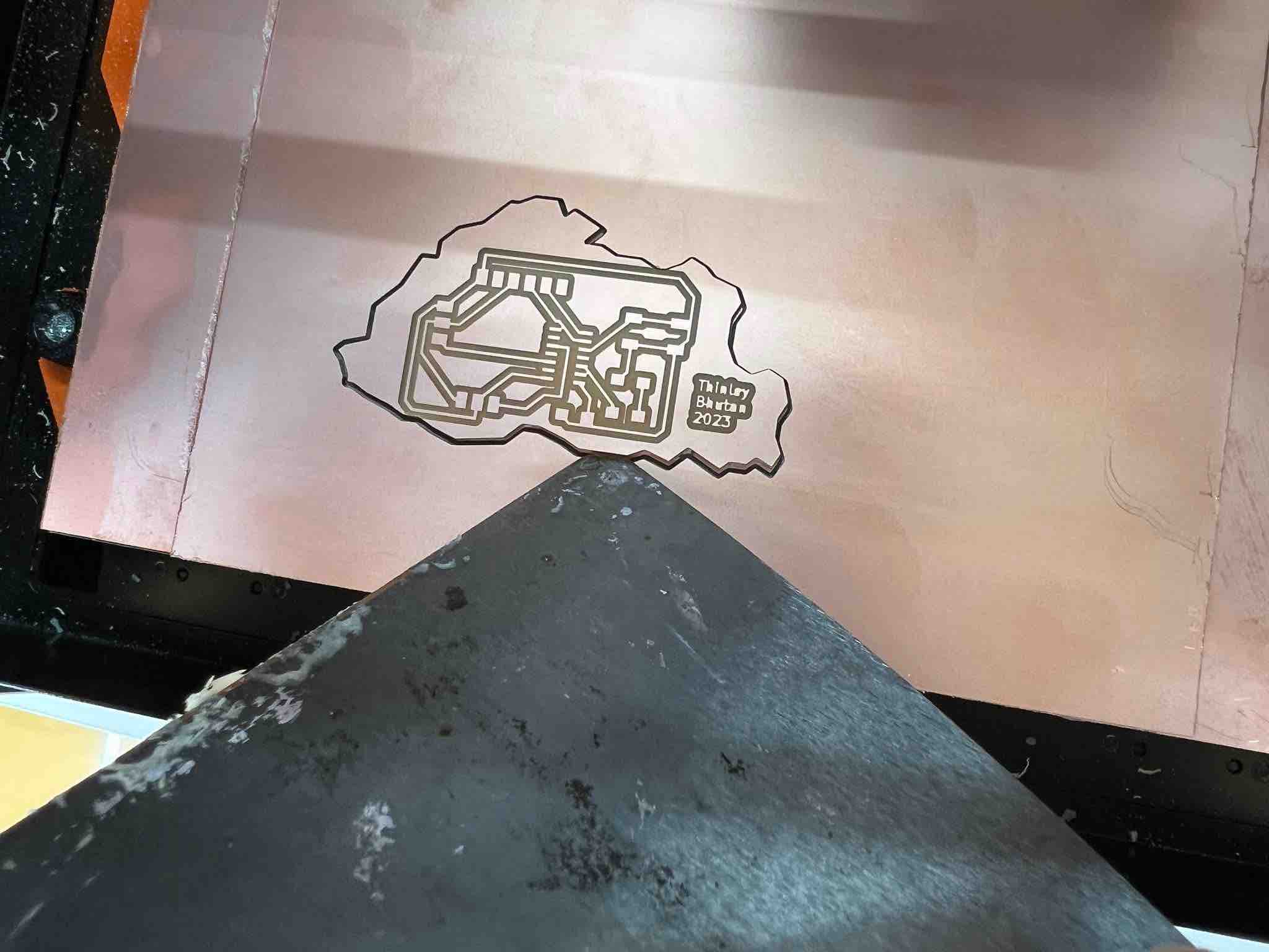
After a while, the traces should be milled. Open the front lid, and use the vacuum to clean the debris.
-
Now for the outline, take the allen key, loosen the bit and remove it. Bring out the
1/32bit and insert it almost all the way with just the enough showing. -
No need to set the XY origin but the Z needs to be set again. Lower your z axis ever so slowly until its almost about ti touch the bed. Then take the allen key and loosen the bit, doing this while holding the bit with your other hand. Once the bit is loosened, slowly drop it till it touches the bed. Then hold the bit and re-tighten it. Hit the
Zunder theSet origin pointto set that location as Z origin. -
On the left had side, set your
cursor steptox100and tap the+zjust once to ensure 1 mm of positive z moment. then close the lid. -
Now you are ready to mill. Select
cuton the right hand side of vpanel andaddyour outline/interior rml file. HitOutputand the cut will begin. -
Once the cut is finished, vacuum and then lift it off carefully using a Scrapper.
UPDI connector
Since the UPDI will be used to program the board, a connector needs to be milled and soldered. I followed the same steps as above but I got the traces and interior from the fabacademy: Embedded programming under the hardware section called the serial UPDI-2-Pin.
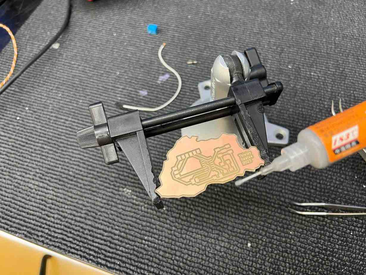
Solder
I had a bit of experience with traditional manual soldering but I am still a beginner. However, I was intrigued by the solder paste reflow method of soldering, so I decided to try using that method. I first applied some past onto the board, then placed my component with a tweazer, and then blew 300 degrees hot air over it with a heat gun. It was a bit difficult at first and a bit messy but I think its definitely easier than traditional manual soldering.
UPDI 2 PIN soldered:
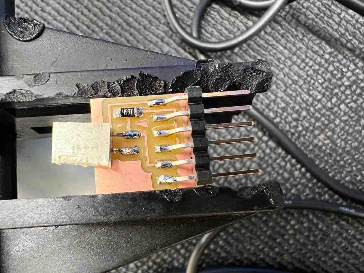
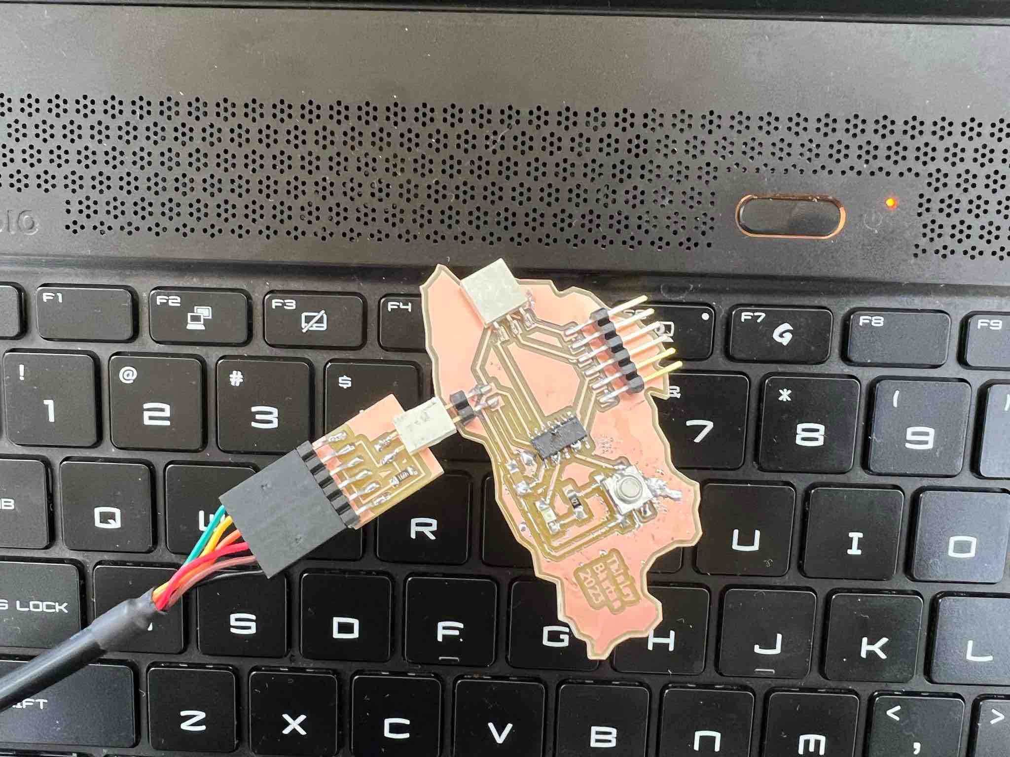
My board and the UPDI connector:
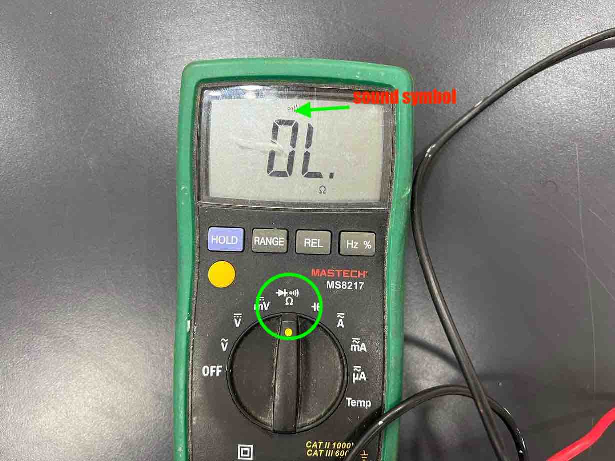
After all the soldering is done, It is essential to check continuity to ensure proper mills and to check for unwanted connections. On the multimeter go to the continuity option which has a sound symbol. Then place the two terminals on two points you want to check. If you hear a beep sound, it means there is a connection between the two.
Debugging
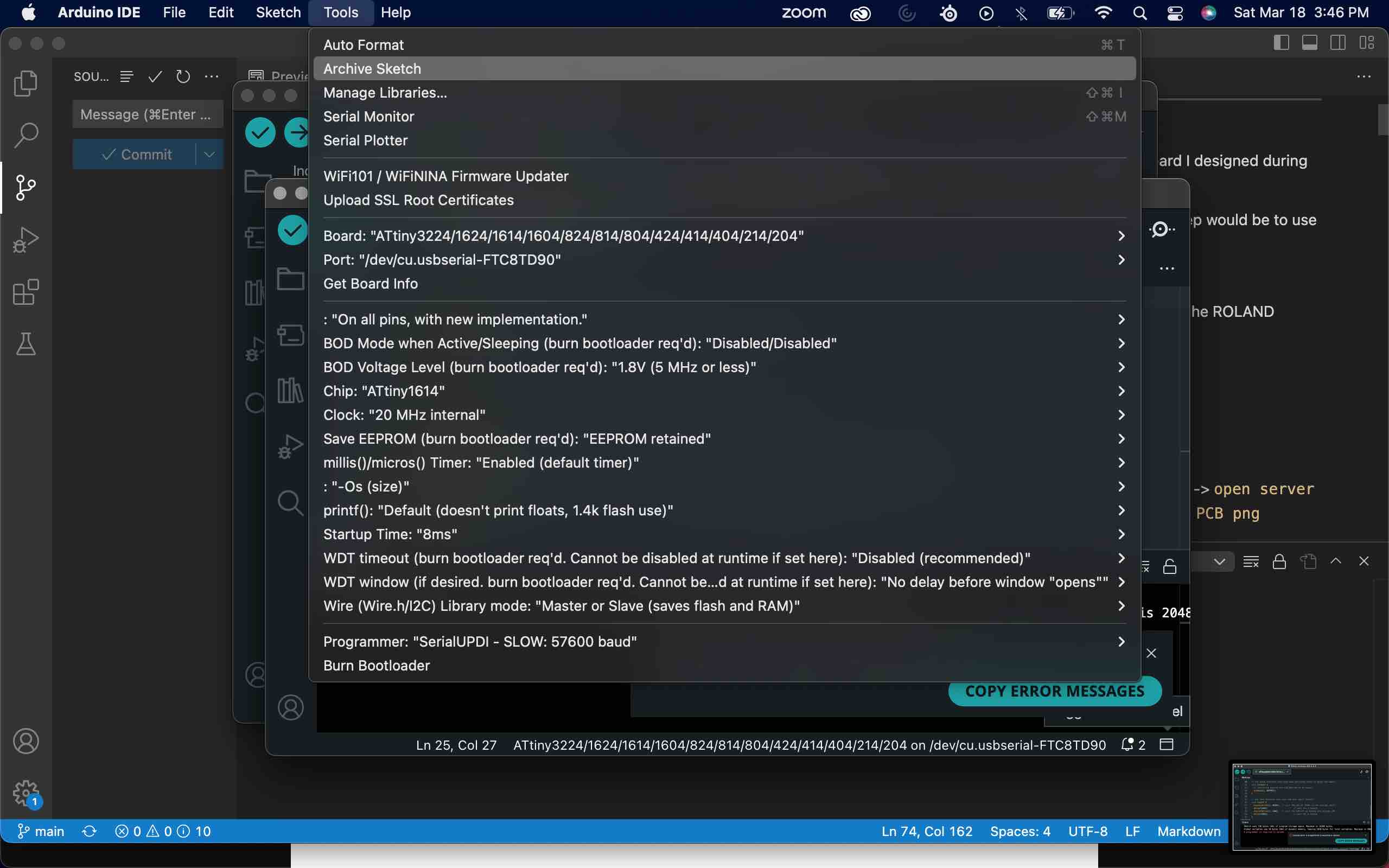
Programming the board after milling and soldering is supposed to be straightforward. You connect your board to the UPDI, which connects to the FTDI, whcih connects to your computer. Then you open Arduino IDE, select your board (for me attiny1614), the port (for me USB), and the programmer (for me serialUPDI slow). But in reality it isn’t as straight forward and this is where debugging comes into play.
Try 1
No matter what I tried, I was not able to load my code into the board. After rounds of checking various things such as the connections and the IDE itself, Zina realized that I connected my attiny1614 in the wrong orientation. Big blunder.
Since I had to re-mill and solder my board again anyway, I decided to change the 2 Pin updi to a 3 pin updi since it was what everyone was doing and had experience with.
Try 2
With my new board, I was confident that I could get something done. However, I kept getting No programmer to upload errors. I tried researching as best I could but I could not find any solid solutions. I reached out to Adrian who was so ready to help and he suggested that I use a different version of the IDE so i went down to version 1.8 from 2.0 and I tried pushing the code and this time it worked better because the computer was actually trying to load the code into the board. But, then I started gettingUPDI initialization failed error and after a back and forth with Adrian, he realized that I made a rookie move and did not have any power connections from the UPDI to my mcu. Big rookie move.
I decided I would make a “frankenstein board” and use an external wire just as a short stop gap to clear the issue.
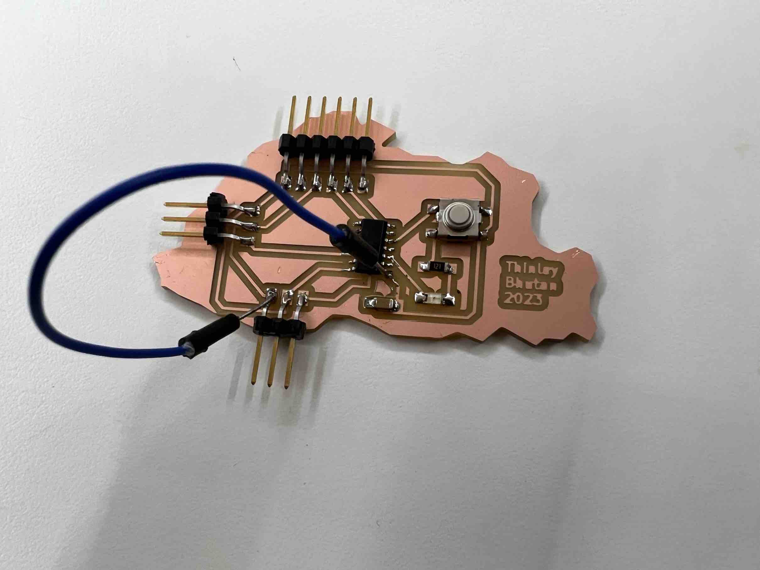
After creating Frank, I tried connecting to my laptops but both couldn’t read the port and it turns out that I was operating very dangerously since when soldering, my capacitors vcc legs had joined with its ground pad creating an unwanted circuit.
Then I tried to desolder the capacitor and its’ legs, but in doing so the entire trace came off so I would have had to re mill my board again.
Try 3
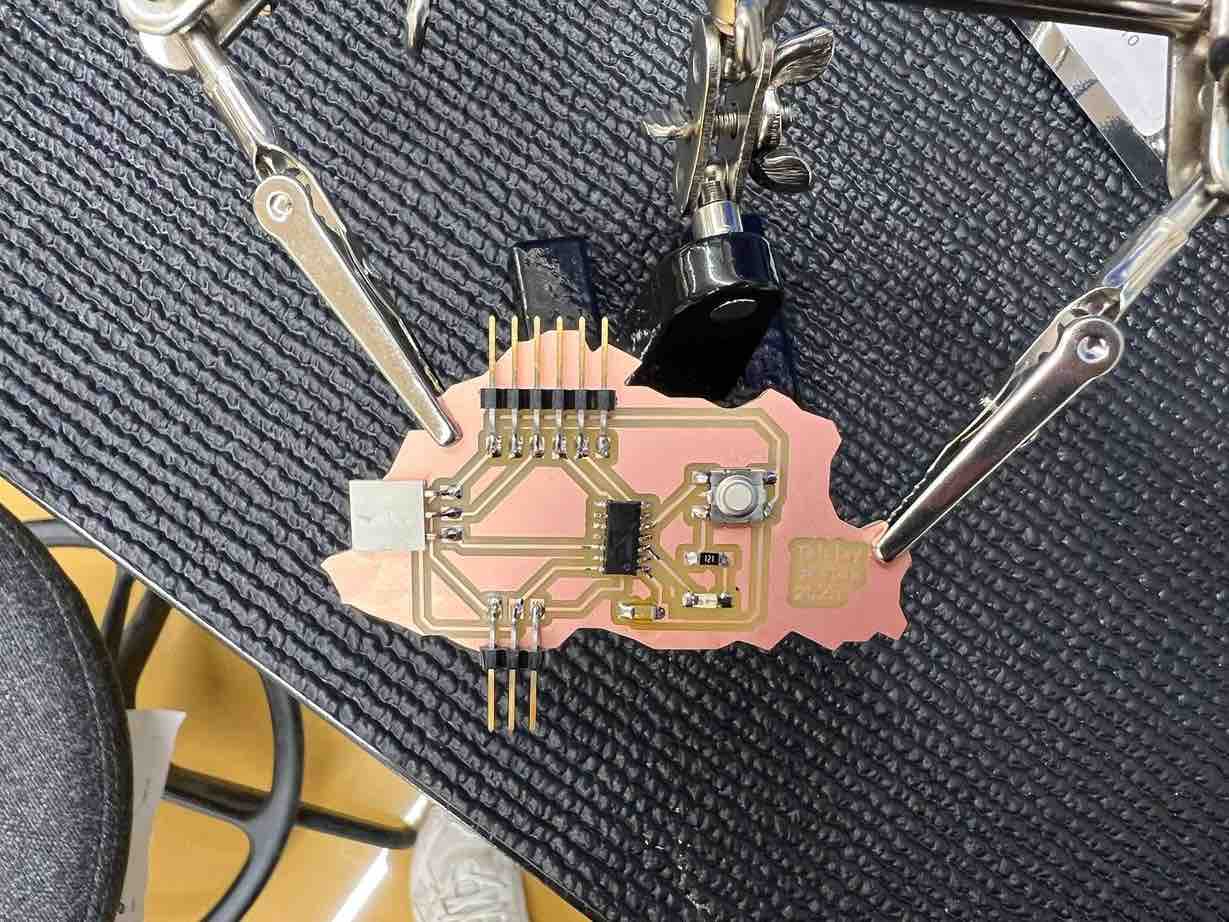
Since I knew that I had improper vcc connections I went ahead and made some tweaks to my schematic and pcb board.
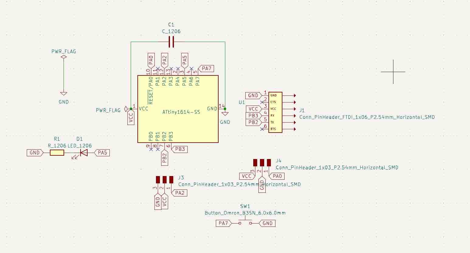
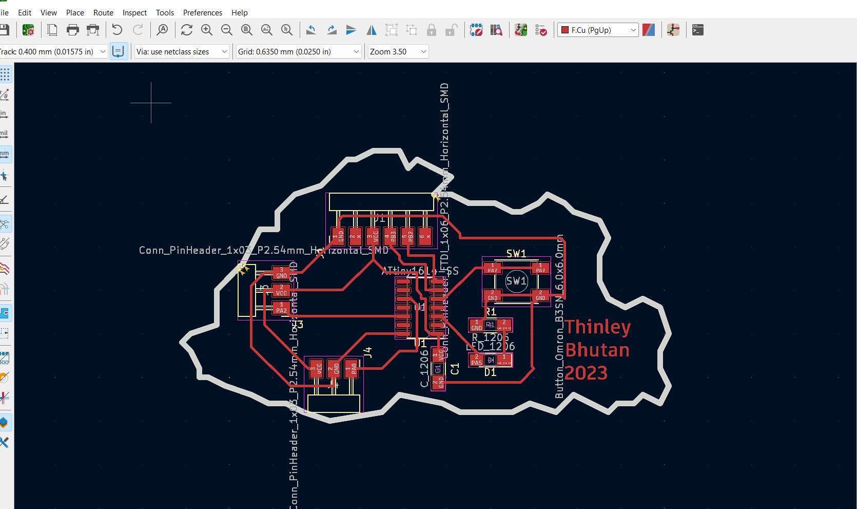
After I was happy with my changes, I went ahead and milled the board.
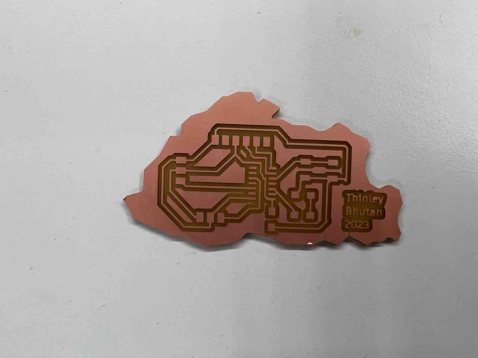
And soldered it:
Shout out to Yeshey for helping me with soldering.
BLINK Example
after soldering my board, I wanted to see if the board was good so I connected it to my board and uploaded arduino's Blink example, and it worked! Naturally I was ecstatic since I went through so much debugging this past week.
Serial Monitor Communication
After the blink example worked I wanted to communicate with my board through the serial monitor. I uploaded the following code, which is an edited version of my code from embedded programming:
Code:
     void setup()


    {
    pinMode(1, OUTPUT);

    Serial.begin(57600);

    while (!Serial);
    Serial.println("Input 1 to turn on the LED");

    }

    void loop() {
    if (Serial.available())
    {
    int state = Serial.parseInt();

    if (state == 1)
    {

    digitalWrite(1, HIGH);
    Serial.println("Orange LED is on");

    }


    }
    }
The program works as follows. The serial monitor prompts the user to enter 1 to turn on the led. If the user inputs 1, then the LED on the board turns on, and the serial monitor returns orange LED is on
After I uploaded the program, it was successful but I serial monitor did not return anything. I was confused, but then I was told that I would need to connect my board through the FTDI pins and as soon as I did, the code ran and my serial monitor worked!
Video:
Button and Servo sweep
Then I wanted to test the functionality of my button and servo motor. I connected a 9g servo to my board and used the following code that I obtained from here and edited.
Code:
    #include <Servo.h>

    Servo myservo;  // create servo object to control a servo
    // twelve servo objects can be created on most boards

    int pos = 0;    // variable to store the servo position

    // constants won't change. They're used here to
    // set pin numbers:
    const int buttonPin = 3;     // the number of the pushbutton pin
    const int myservoPin=  9;      // the number of the servo pin

    // variables will change:
    int buttonState = 0;         // variable for reading the pushbutton status

    void setup() {
    myservo.attach(9);  // attaches the servo on pin 9 to the servo object

    pinMode(buttonPin, INPUT);
    pinMode(buttonPin,INPUT_PULLUP);
    }

    void checkButton(){
    buttonState = digitalRead(buttonPin);

    while(buttonState == HIGH)
    buttonState = digitalRead(buttonPin);

    }
    void loop() {
    for (pos = 0; pos <= 180; pos += 1) { // goes from 0 degrees to 180 degrees
    // in steps of 1 degree
    myservo.write(pos); // tell servo to go to position in variable 'pos'
    delay(10);                       // waits 15ms for the servo to reach the position
    checkButton();

    }
    for (pos = 180; pos >= 0; pos -= 1) { // goes from 180 degrees to 0 degrees
    myservo.write(pos);              // tell servo to go to position in variable 'pos'
    delay(10);                       // waits 15ms for the servo to reach the position
    checkButton();

    }
    }
While I press the button, the servo will undergo a sweep motion from 0 to 180 degrees.
Video:
Electronics FAQs:
-
What is a circuit?
It is a complete conductive path through which electricity flows through. * > What are different power sources?
The two most commons types of power sources are ``AC (alternating current)`` and ``DC (direct current)``. In AC the current changes direction periodically while in DC the current flows in one fixed direction.
-
What is a Load?
It is a device that consumes electric power and transforms it into other forms -
What is a conductor?
It is a substance or material that allows electric current to flow through it. -
What is the difference between Voltage, Current and Resistance?
Current (measured in amps) is defined as the rate of flow of charge, while voltage (measured in volts) is the difference in charge between two points. Resistance (measured in ohms) is the materials ability ti resist the flow of current. -
What is Ohm’s Law?
Ohm's law states that the voltage across a conductor is directly proportional to the current flowing through it, provided all physical conditions and temperatures remain constant. -
What does a Resistor do?
A resistor restricts the amount of flow of current. Typically used to protect other components by reducing the flow of current into it. -
What does a Capacitor do?
A capacitor stores energy temporarily and can discharge the energy very quickly. They have high power densities. -
What does a Diode do?
A diode allows for current to flow in only one direction. -
What does LED mean?
LED stands for Light emitting diode. It emits light when current flows through it.
-
What is a Regulator?
It is a device that regulates the voltage to maintain a fixed voltage, during power fluctuations and variations in loads. -
What is a Bypass Capacitor?
It is a capacitor that is placed between DC and ground to remove any AC components of the signal. -
What is a Current Limiting Resistor for an LED do?
A current limiting resistor limits the amount of current that will flow through the LED and it also regulates the difference in voltage drops between the LED and power supply. -
How are Capacitors used as High-pass and Low-pass filters? What does it filter?
High pass filters block the low frequency signals and allows the high frequency to pass while low pass filters do the opposite and block the high frequency signal while allowing the low frequency to pass. A capacitor can be used as both as it can block DC signals which are low frequency and while allowing high frequency AC signals to pass through. -
What is VCC?
VCC or Voltage Common collector is the power input of the device. -
What is GND?
GND is just a short form for Ground. It carries a voltage of 0 V -
What is Common Ground?
It is the reference point for all signals or a common path in a circuit where we can measure all the voltages. -
What is a Ground Plane and why is it used?
A ground plane is a a large areas electrically conductive surface connected to the circuit's ground point. It is typically used to provide ground connections to those components who cannot be connected to ground due to routing issues.