Week 13. Networking and Communications
Group Assignment
Link to the group assignment: Boys Wireless
Individual Assignment
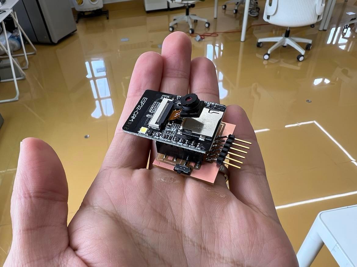
For this week I wanted to work with a ESP32 CAM since it has a big relevance to my final project (drone). It will be nice to figure out how to use a ESP32 CAM for my final project since it has WIFI, Bluetooth and a camera integrated in one system.
The ESP32-CAM is a ESP32 based camera module. The camera is a 2 mega pixel called the OV2640.
Milling and Production
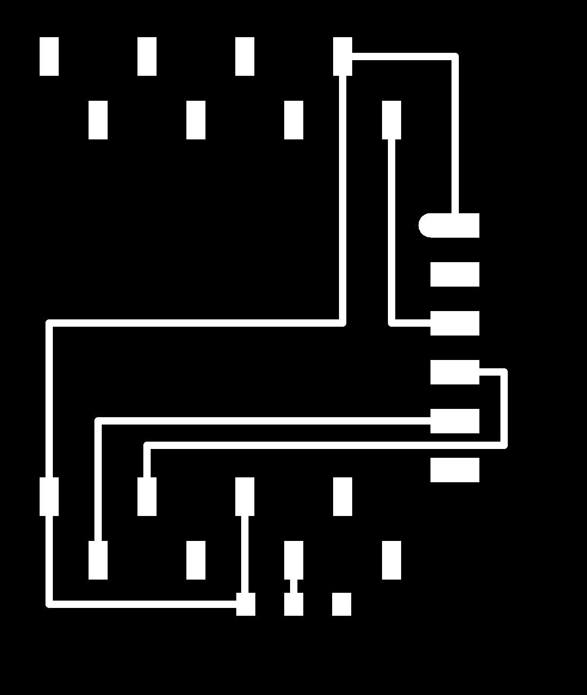
From the FabAcademy Website for Networking and communications week, I downloaded professor Neil’s ESP320-CAM boards’ interior and traces. This is because the ESP32-CAM cannot be programmed directly (no access points), so one has to either mill a board like how I am going to or have a FTDI programming module.
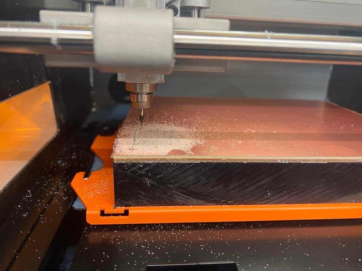
I then Used MODS to create the rml files for the two and then milled it using the ROLAND SRM20. I used a 1/64” bit for the traces and 1/32” for the outline.
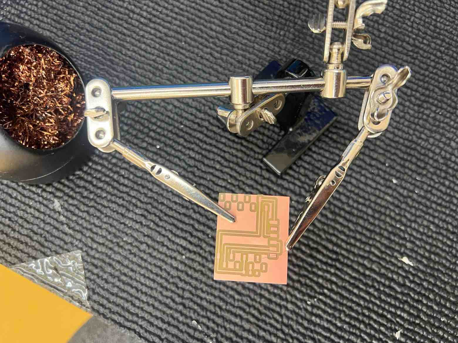
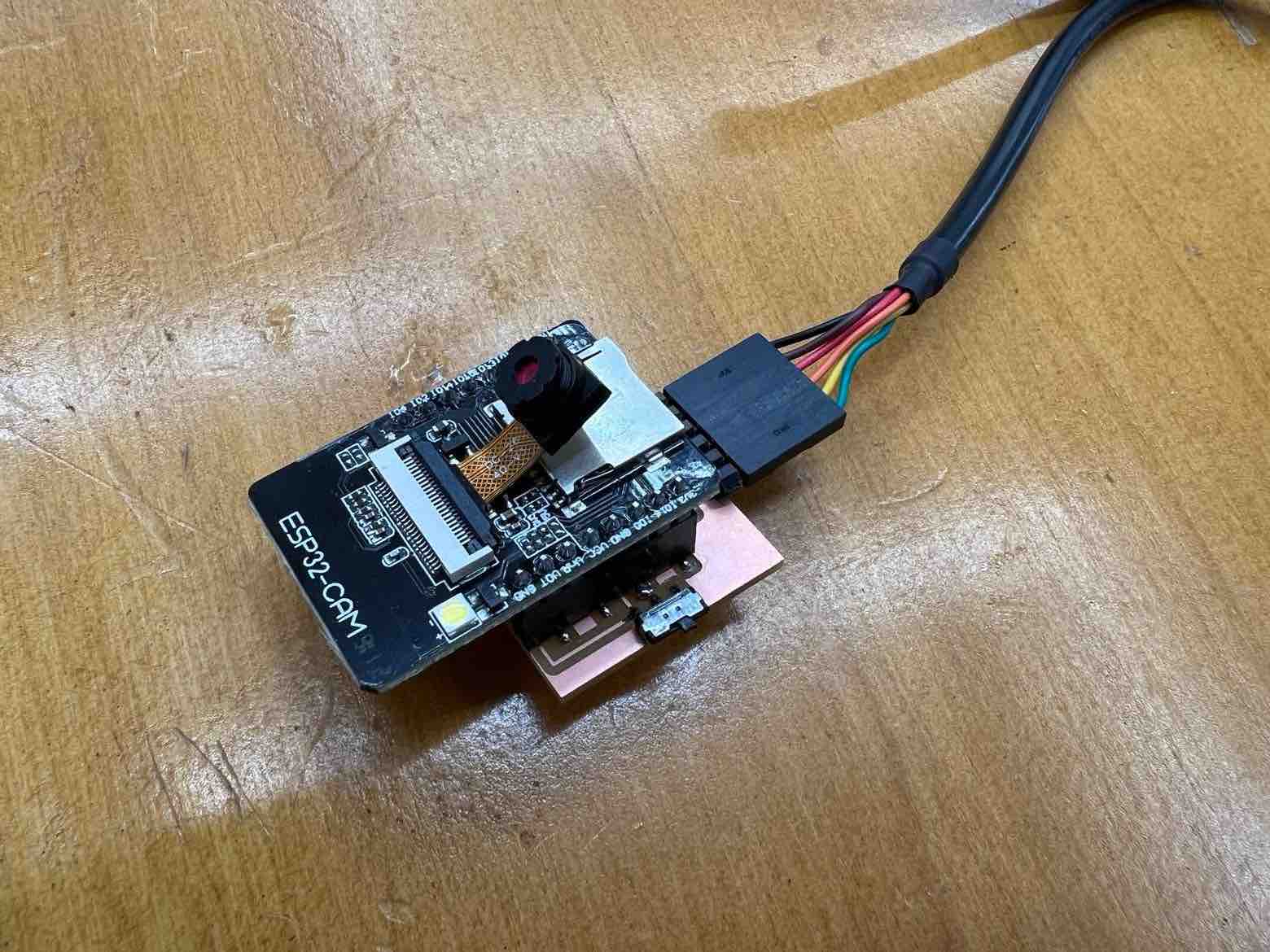
After successful milling, collected the required components: * 2x 1x8 2.54mm connectors * 1x Switch Slide * 6 pin Header for the FTDI
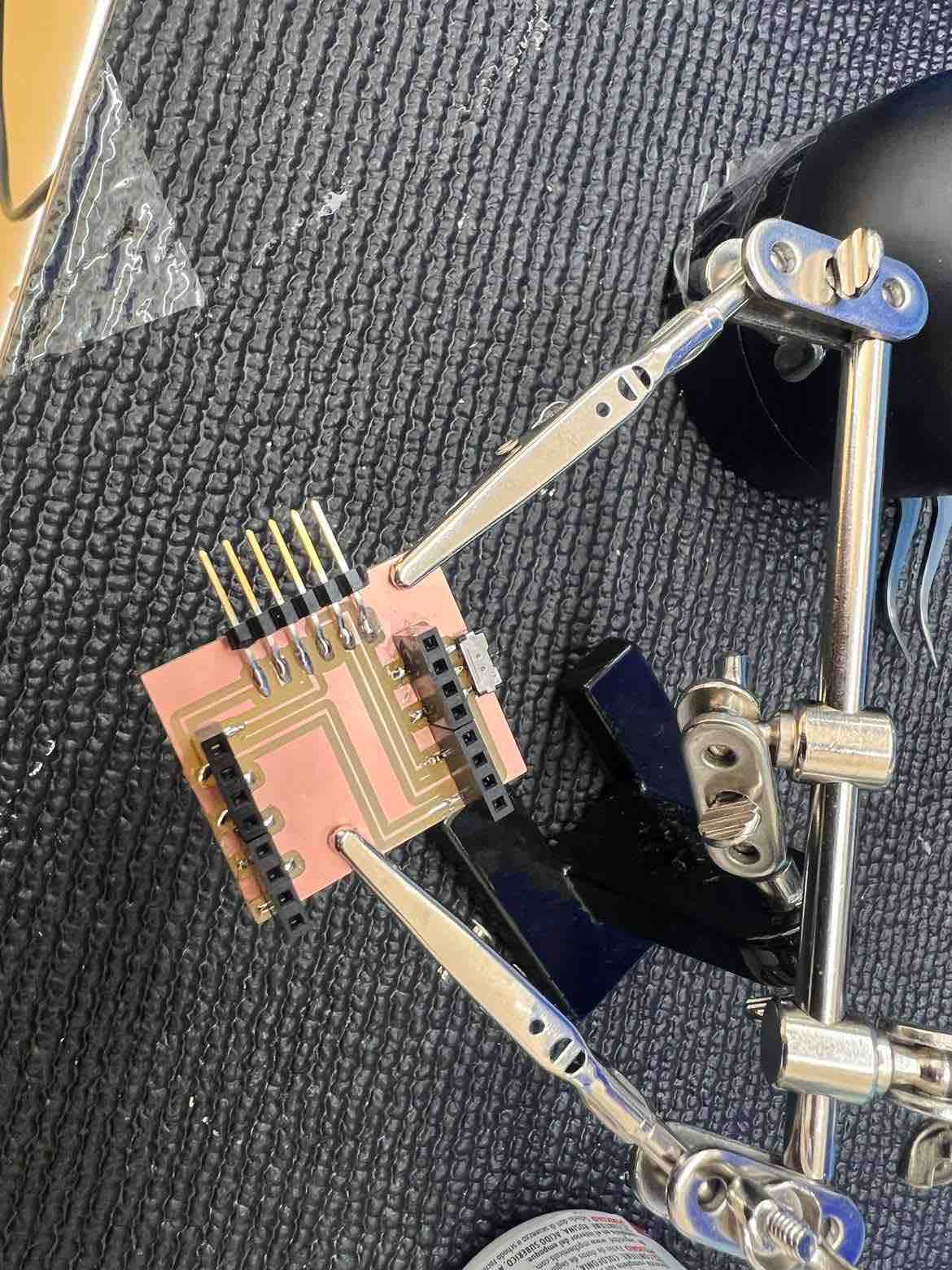
Then I moved onto the soldering station and soldered the board. Then I attached the ESP32-CAM onto the new board.
Arduino IDE
Board Manager:
I already had the espressif esp32 package installed but these are the steps to do it:
-
In the arduino IDE, go to
preferencesand add this url to the additional boards manager URL:https://raw.githubusercontent.com/espressif/arduino-esp32/gh-pages/package_esp32_index.json -
go to
tools- >boards-> manage boards and download and installesp32
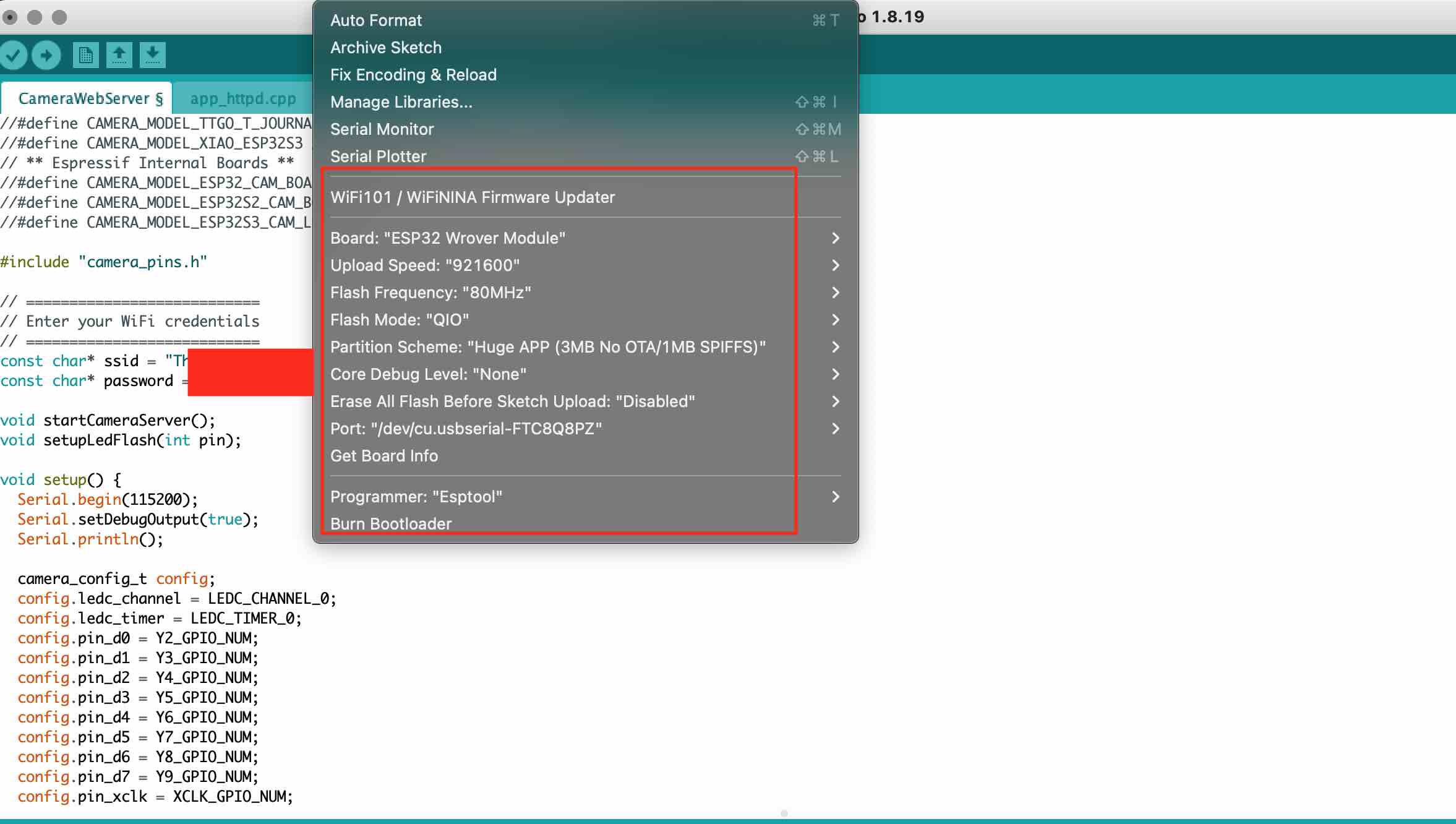
The settings I used for my board under the tools manager:
Programming in Arduino IDE
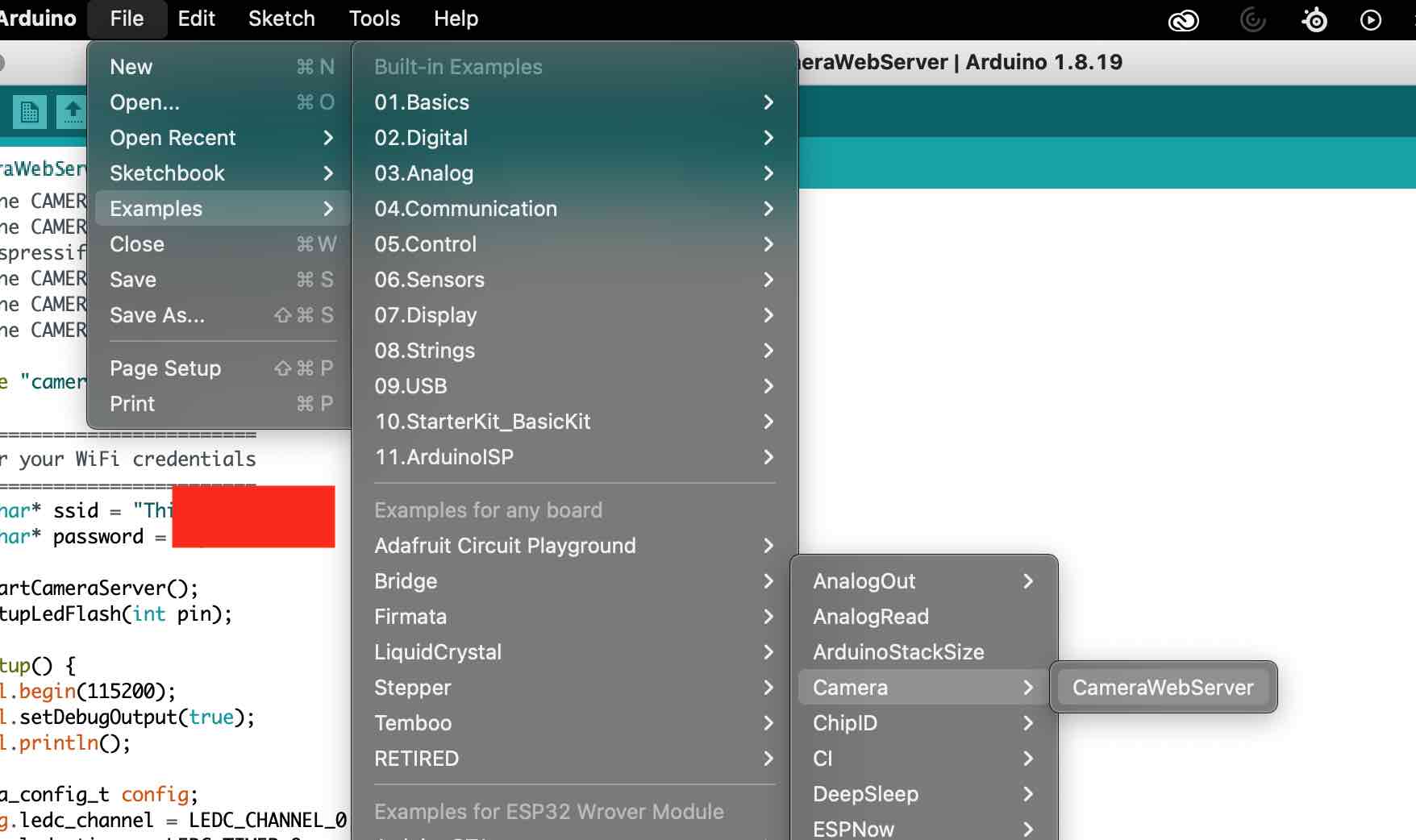
The next step is to work on the programming in the Arduino IDE. The code I will use is a slightly edited version of the CameraWebServer Example:
I went to files->examples ->ESP32->Camera ->CameraWebServer
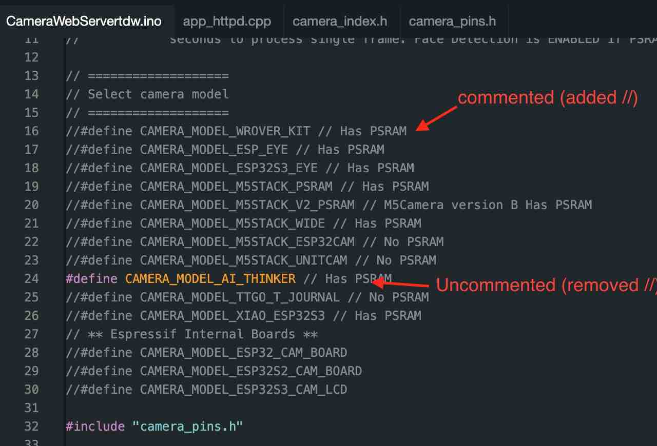
I only made three changes to the CameraWebServer example.
- First I commented (//) the
#define CAMERA_MODEL_WROVER_KITand then uncommented theCAMERA_MODEL_AI_THINKER - Then I changed the SSID to the SSID of my WIFI
- And then changed the password (to the password of my WIFI)
The purpose of this code is to program the ESP32-CAM and to obtain its IP address.
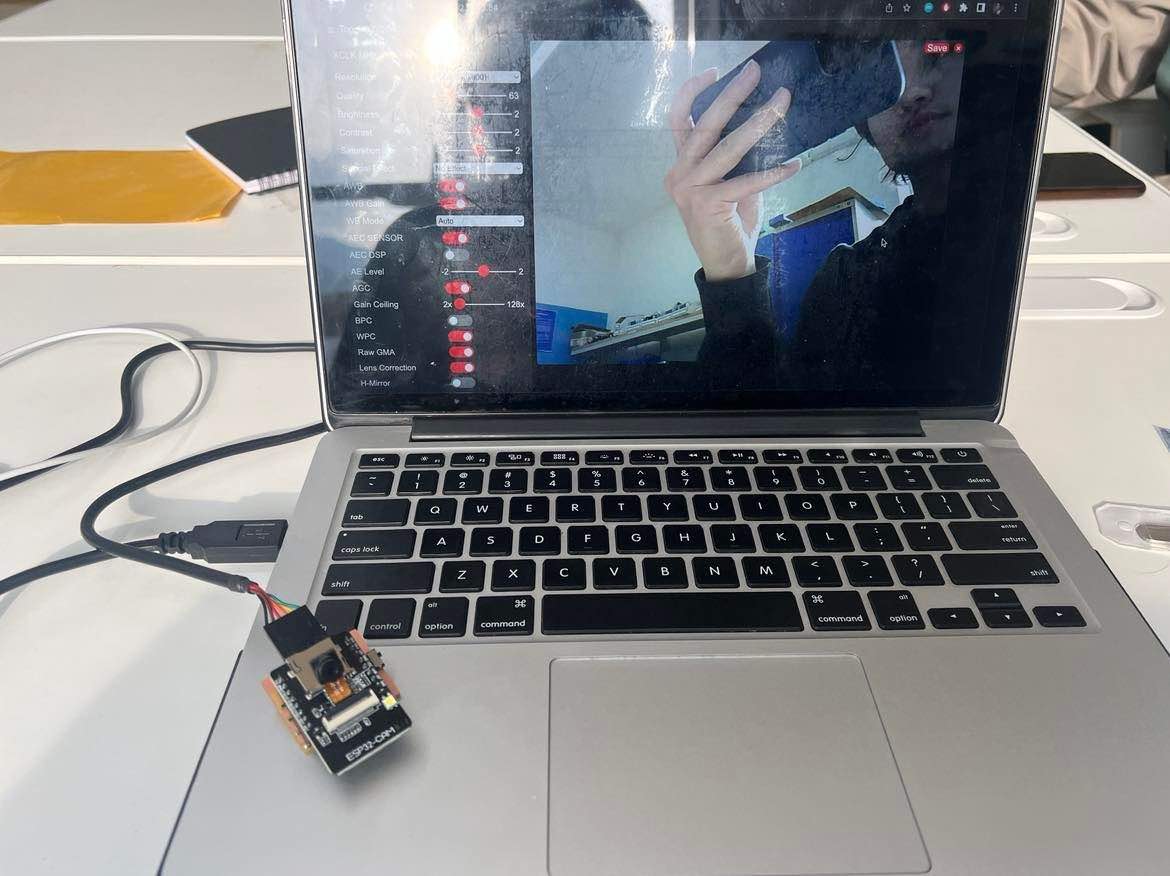
With the code done, I connected the ESP32-CAM with the new milled board to my laptop using a FTDI cable. Then, I complied and uploaded the code.
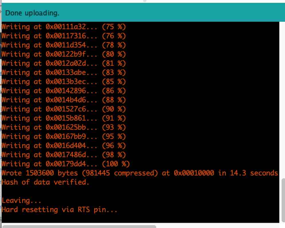
Once the upload is successfully complete,
- Open the
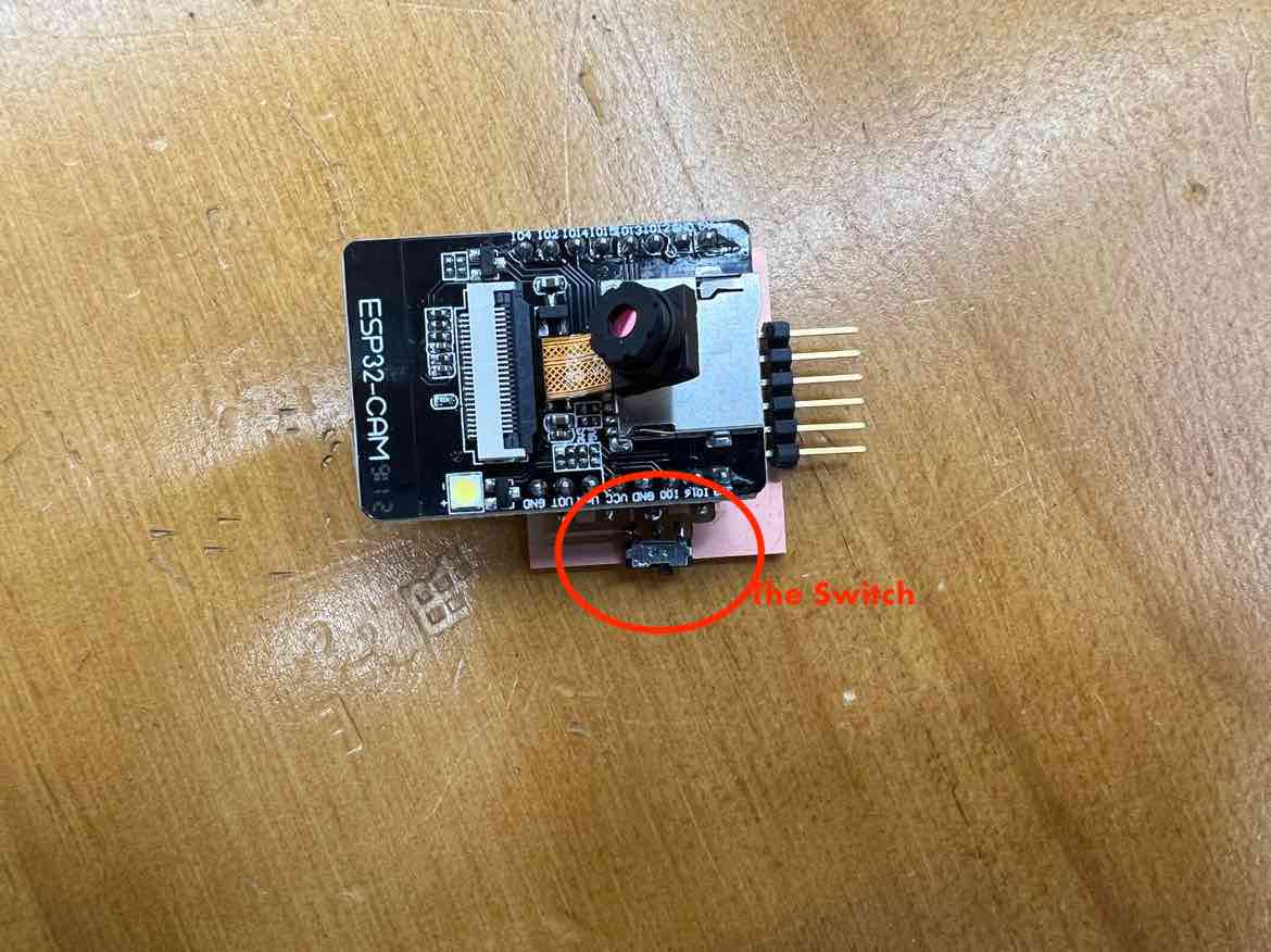
serial monitor, - turn the switch on the board,
- hit the reset button on the ESP.
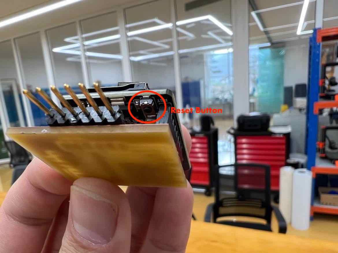
Then you will find your Camera’s Ip address in the Serial Monitor as seen below:
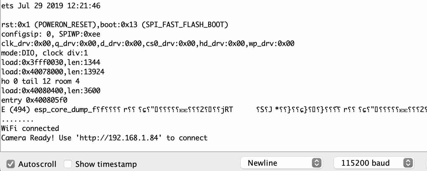
An issue I ran into was, when I opened the serial monitor, i would just see ......... and would never get my IP address. I was under the impression that one had to give a random SSID and password for future protection and it completely slipped my mind that I needed to use the SSID and password of my wifi. It also did not work when connected to the 5GHz wifi and only worked once I used the wifi SSID and password of the 2.5 GHz.
The Camera
Now finally to access the camera, take the newly obtained Ip address from the Serial monitor, copy it and then paste it in your web browser (Google chrome).
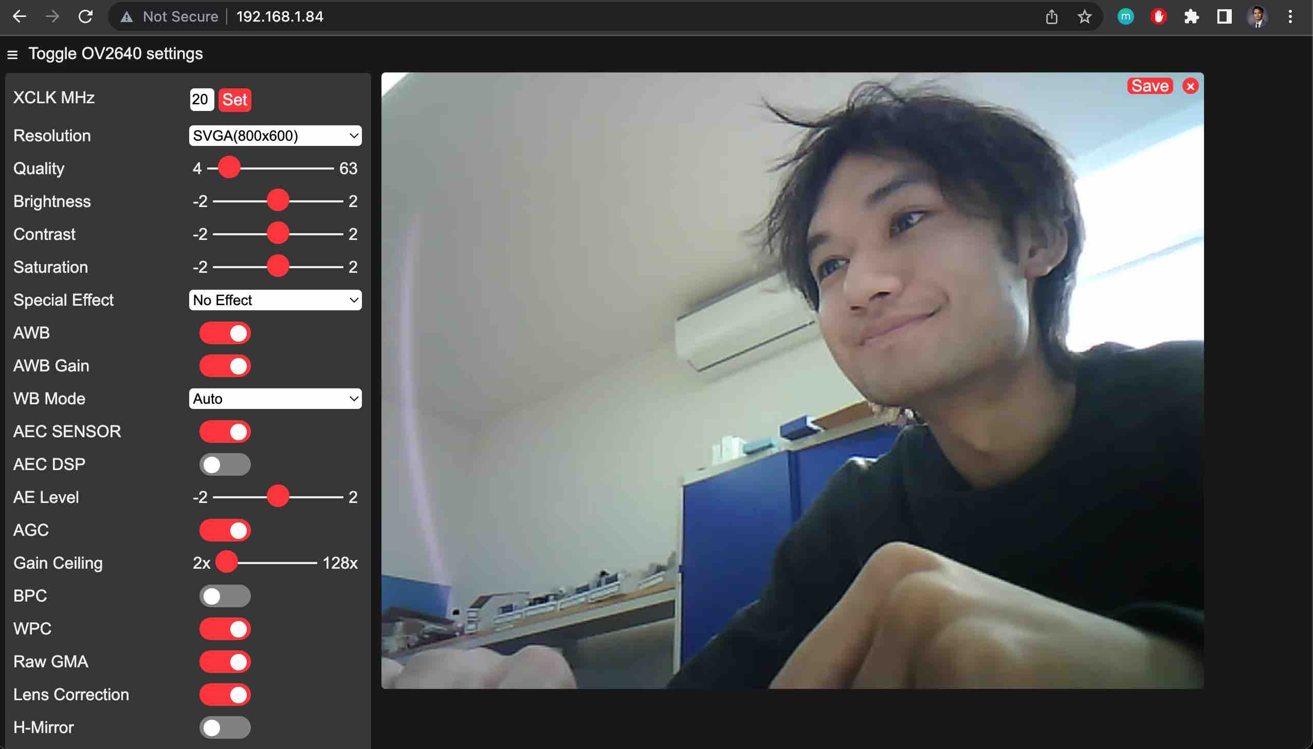
The OV2640 camera’s web app page opens up as seen above, and here once you hit Start Streaming, your camera will start up and will be active.
You can change and edit a lot of the settings on the camera’s web app but all I changed was the resolution, setting it to SVGA(800x600)
Video:
Trouble Shooting Guide:
A very helpful website with various solutions to common errors: Link
The video by professor Neil on programming the ESP 32CAM is a helpful resource. Incase you are stuck somewhere.
Design Files
CameraWebServe Arduino files: