Week 11. Input Devices
Group Assignment
Link to group assignment: Bhutan Week 11
We played around with two input devices connected to an arduino for the week.I soldered the resistor and wire to the copper tape to create a Capacitive Touch Sensor.
Individual Assignment
For this weeks individual assignment, I wanted to play around with different input devices but especially those related to my final project. I wanted to begin with a potentiometer since I could connect it to my already designed and fabricated Bhutan board. Then I plan on connecting two frankenstein wires to the same board and want to test a capacitive sensor. Then finally if we can get a joystick, design and fabricate a new board to which I can connect the joystick to. Doing all this in spirals of course.
Potentiometer
Seeing as my Bhutan board already has a three pin connector, I thought a potentiometer would be the perfect input device to start with also considering how I will need to know how this works for my drone’s controller.
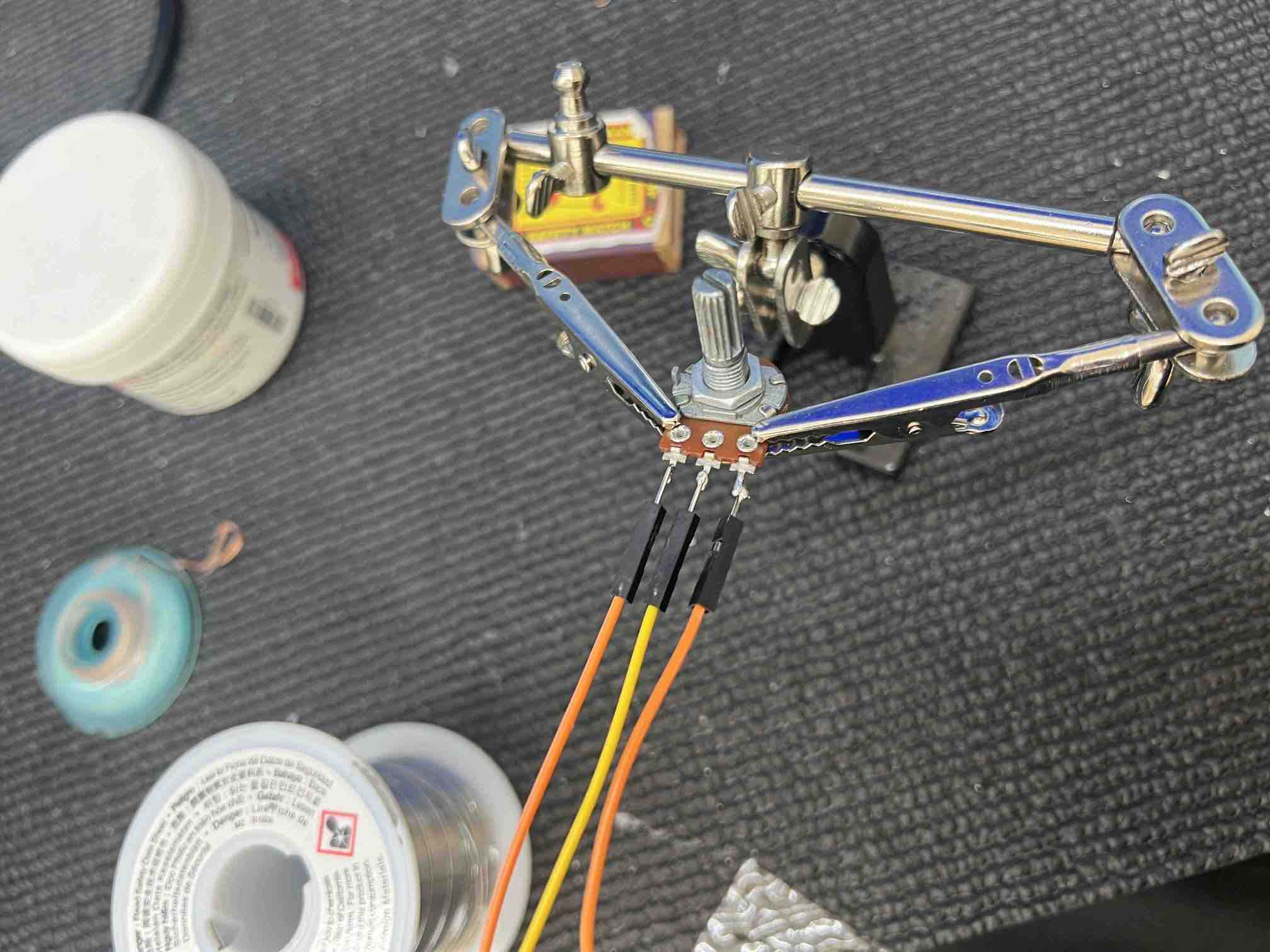
First I found a potentiometer in the lab and then soldered 3 male-female wires to the three connections on the potentiometer:
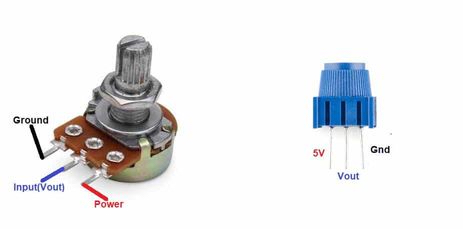
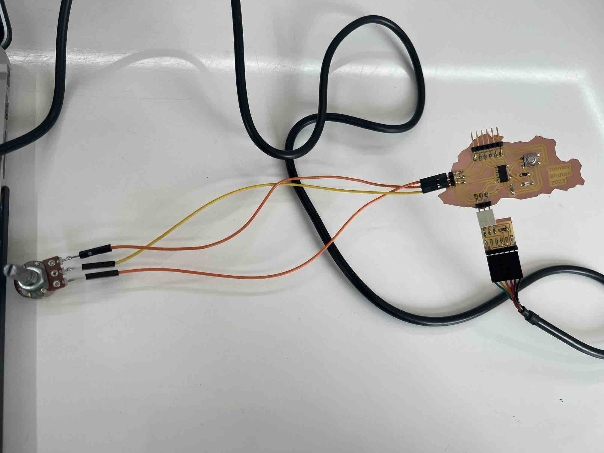
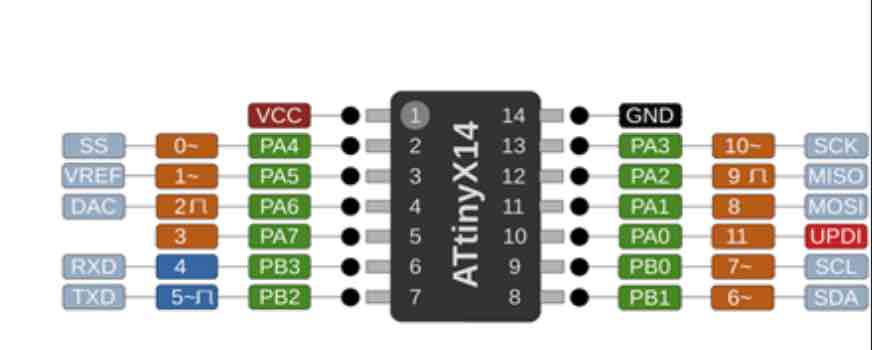
Then I connected the potentiometer to my Bhutan board, keeping in mind the pins and labels of the potentiometer. For this I referred to the image below:
Then I asked ChatGPT how one could activate the potentiometer and it helped with starting the code. I wanted to make it so that the brightness of the LED would be controlled by the potentiometer.
As you can see below, everything worked as expected and I was able to control the intensity of the brightness of my LED using the potentiometer.
Code:
    const int LED_PIN = 1;
    const int POT_PIN = 9;

    void setup() {
    pinMode(LED_PIN, OUTPUT);
    }

    void loop() {

    int potValue = analogRead(POT_PIN); //Potentiometer Value

    int brightness = map(potValue, 0, 1023, 0, 255);

    analogWrite(LED_PIN, brightness);
    }
Capacitive Sensor
The next input device that I wanted to work with was the capacitive sensor. Rico showed us a demo of one working so I was intrigued and wanted ti give it a go.
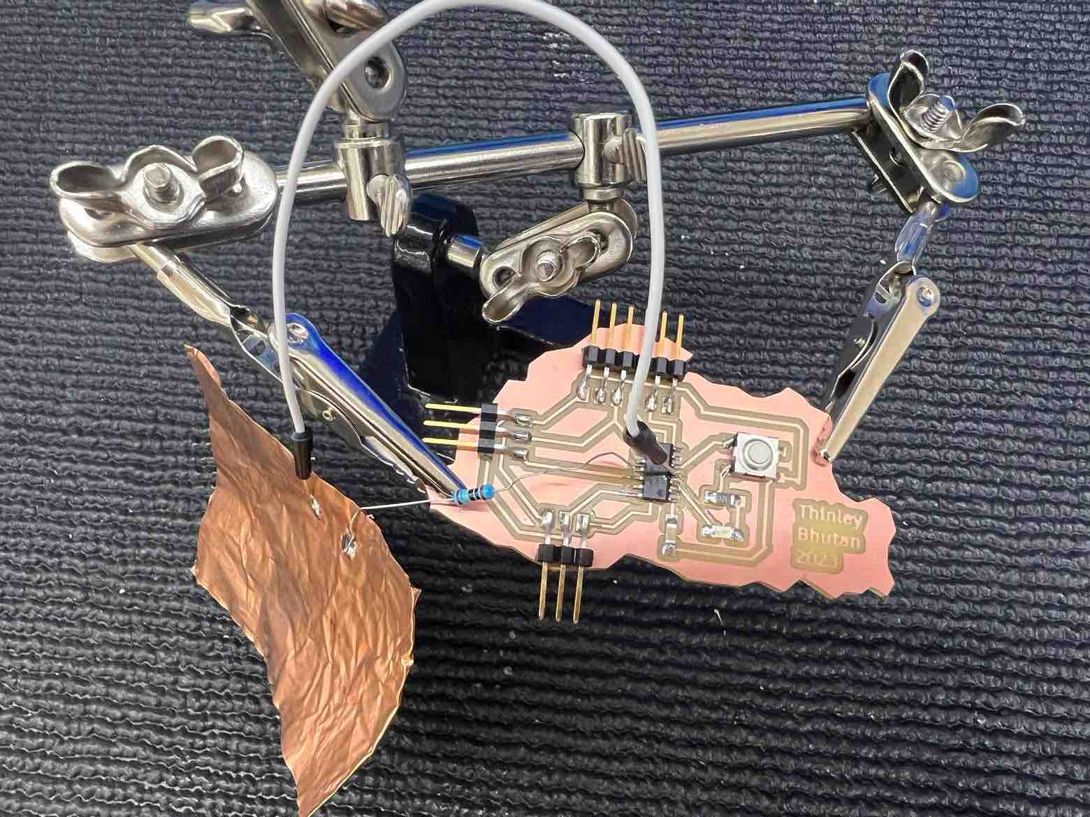
I took some copper tape and solder a jumper wire and a 1 Mega ohm resistor on it. Then I soldered it onto my Bhutan Board, to pins number 8 and 2.
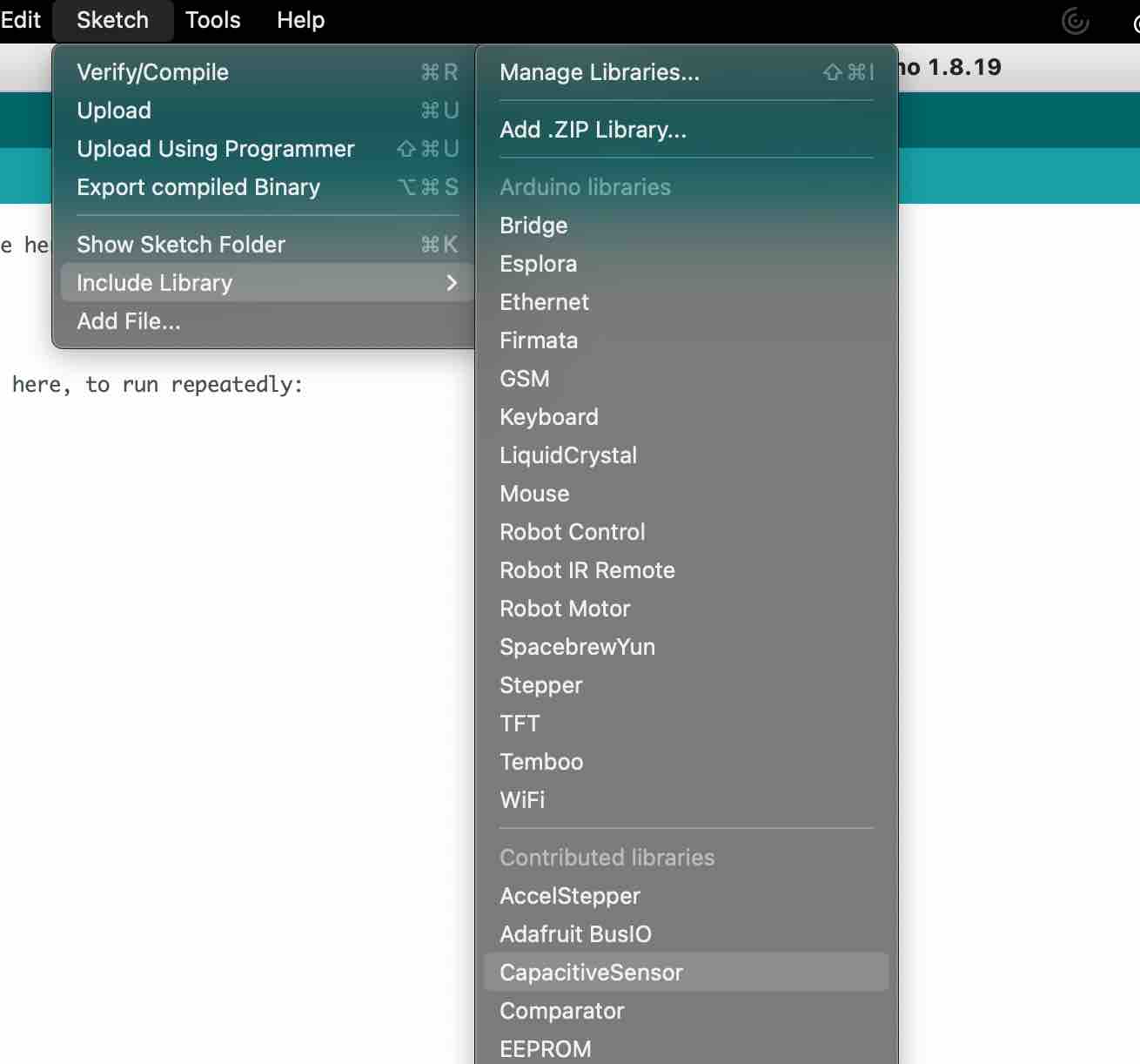
Then in the Arduino IDE, I went to tool -> manage libraries and installed CapacitiveSensor.
Then I opened the example code: CapacitorSensorSketch under File-> examples -> CapacitveSensor.
You can see the code below, I ensured to remove the second and third sensors from the code and changed the pins to 8 and 2 to reflect my connections.
Code:
    #include <CapacitiveSensor.h>

    /*
    * CapitiveSense Library Demo Sketch
    * Paul Badger 2008
    * Uses a high value resistor e.g. 10M between send pin and receive pin
    * Resistor effects sensitivity, experiment with values, 50K - 50M. Larger resistor values yield larger sensor values.
    * Receive pin is the sensor pin - try different amounts of foil/metal on this pin
    */


    CapacitiveSensor   cs_8_2 = CapacitiveSensor(8,2);        // 10M resistor between pins 4 & 2, pin 2 is sensor pin, add a wire and or foil if desired
    // 10M resistor between pins 4 & 8, pin 8 is sensor pin, add a wire and or foil

    void setup()
    {
    cs_8_2.set_CS_AutocaL_Millis(0xFFFFFFFF);     // turn off autocalibrate on channel 1 - just as an example
    Serial.begin(9600);
    }

    void loop()
    {
    long start = millis();
    long total1 =  cs_8_2.capacitiveSensor(30);

    Serial.print(millis() - start);        // check on performance in milliseconds
    Serial.print("\t");                    // tab character for debug window spacing

    Serial.print(total1);                  // print sensor output 1
    Serial.print("\t");
                    // print sensor output 3

    delay(10);                             // arbitrary delay to limit data to serial port
    }
Video of it working:
From the Video you can see that the serial monitor displays a smaller number when not in proximity to the sensor but once I hold on to it, the number increases drastically upon sensing touch.
This week it was especially cool to learn how to make a touch sensor, using something simple as a piece of copper sheet. Another takeaway is that when designing your own board, its good to have as many input or output pins as possible even if you don’t need them at the time.
Luckily for the capacitive touch, I was able to get stable measurements by soldering the wires well, and also since I used the example code, the calibration was done in the code. Same for the potentiometer, since the board read the potentiometer’s analog data, it was easy to match it to the LED’s brightness (using the map function).
Design Files
Arduino Files: