Week 2. Computer-aided Design
This week we explored various 2D as well as 3D design tools.
I first began by ensuring that I had a good amount of useful softwares downloaded for both the 2D as well as 3D. The Following softwares are the ones that I downloaded (with download links) for now:
- Imagemagick
- Gimp
- Inkscape
- Solidworks (already had a license)
- Fusion360
- FreeCAD
- ffmpeg
- Help for this: ffmpeg tutorial- using git clone/pip install
- Losslesscut
2D Design
INKSCAPE
Raster vs Vector * Machines in the fablab accept Raster and Vector * Raster: in Pixels * Vector: Mathematical * We should be able to go from raster to vector and vice versa * Machines that follow a path use Vector * Other machines use Raster. (Rasters grey scale can be used as a 3D model)(Raster in laser cutting will engrave rather then cut) * Typically: vector: cut || Raster: Engrave
To explore this aspect of raster vs vector, I utilized Inkscape. Below you can see the typical workflow for converting from raster to vector and vice-versa.
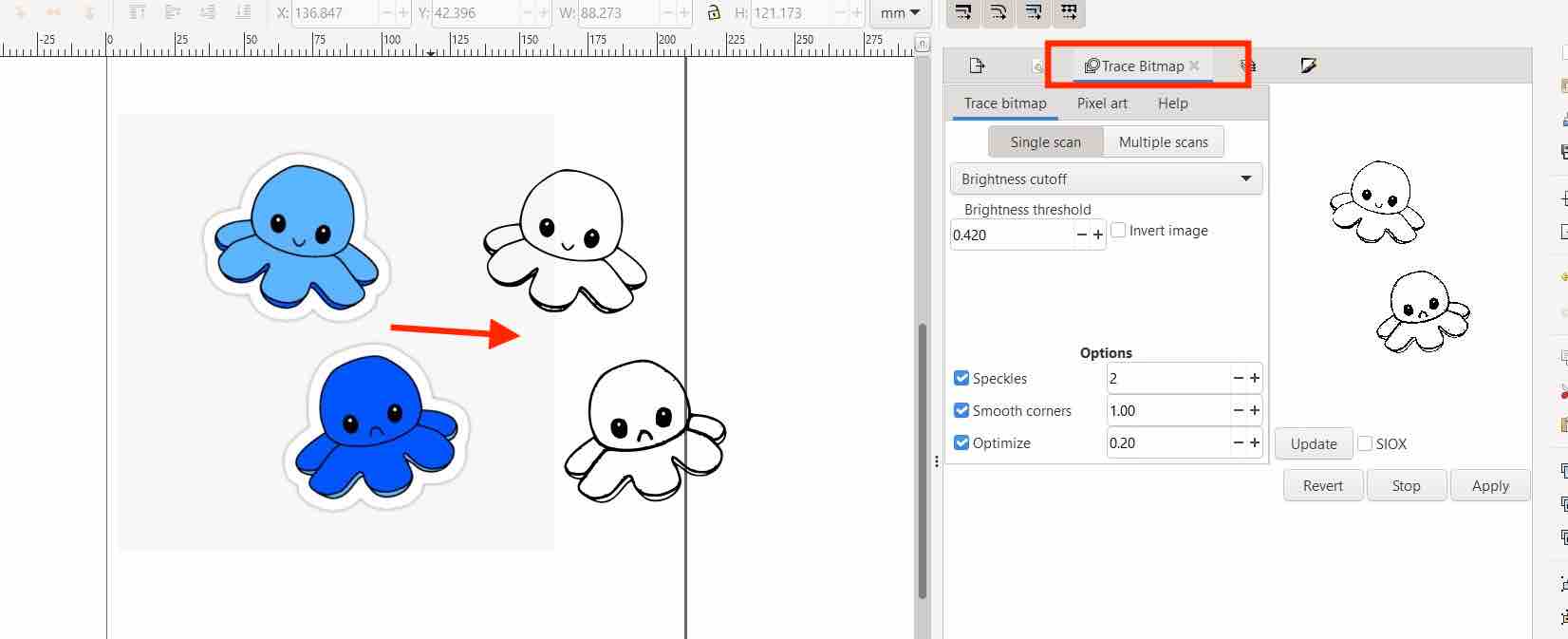
Raster to Vector
- Upload raster png
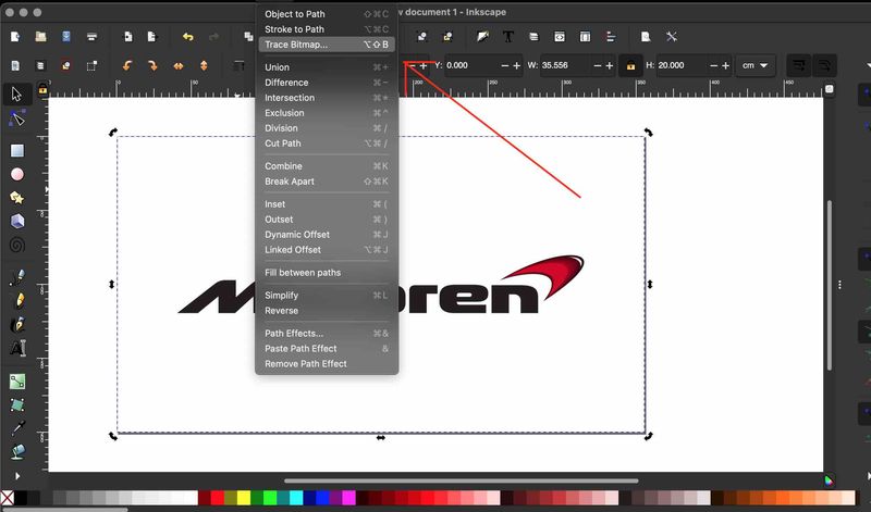
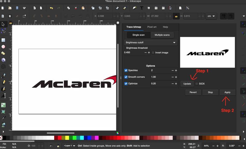
- click on the drawing and click
Trace Bitmap - Single Scan for Black&White
- Multiple Scan for Coloured
- Adjust Brightness cutoff: higher number makes the line thicker
- Click apply once you are done editing and tracing
- Hit the lock icon to keep aspect ratio
- W = 210 mm for A4 size
- Click
document propertiesto check sizing - Resize page to drawing
- After editing parameters for the white space
- Hit Resize page to drawing again
- And save file in proper folder
Example of the Workflow:
Vector to Raster
- File-> export png image -> page
- For printing dpi = 200-300
- For machines dpi = 600
- For super precise (pcbs etc) = 1200
- 5cm wide ideal size for documentation
- Choose proper folder and save
Raster (can see how pixelated it is) vs Vector:


GIMP
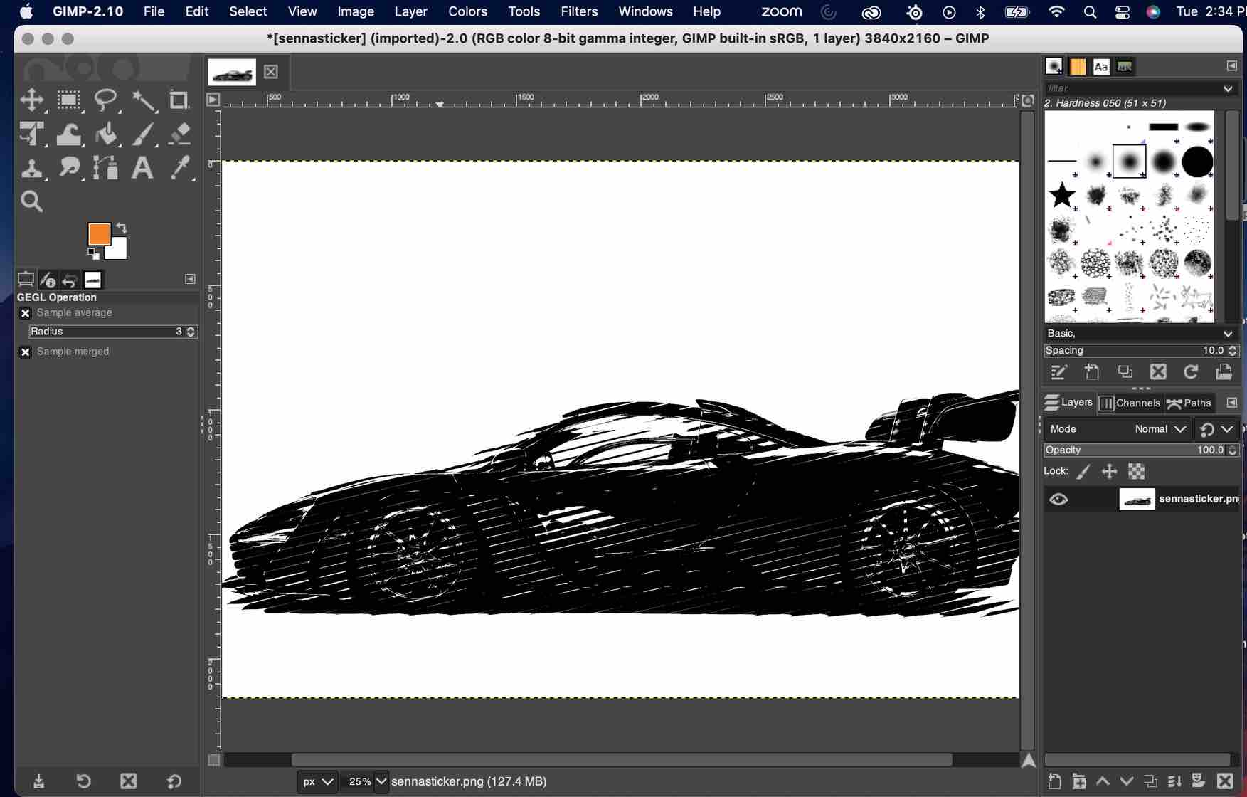
I messed around with GIMP and wanted to halftone my image to make a “real life” image vinyl cut-able. To halftone the image, I used the newsprint filter.
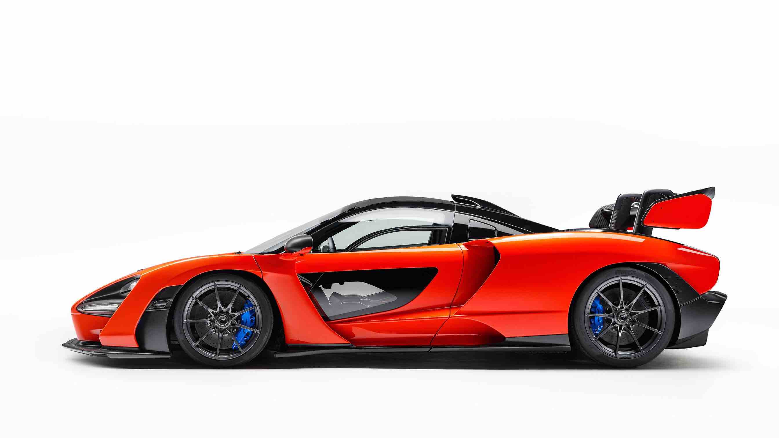
I took an image of a McLaren Senna, my favourite car, and I half-toned it to make it a sticker.
Steps for Half-toning:
- import the jpg/png
- adjust brightness/contrast
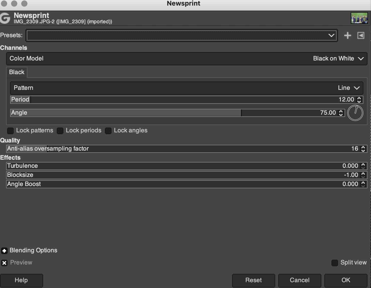
- distort -> newsprint
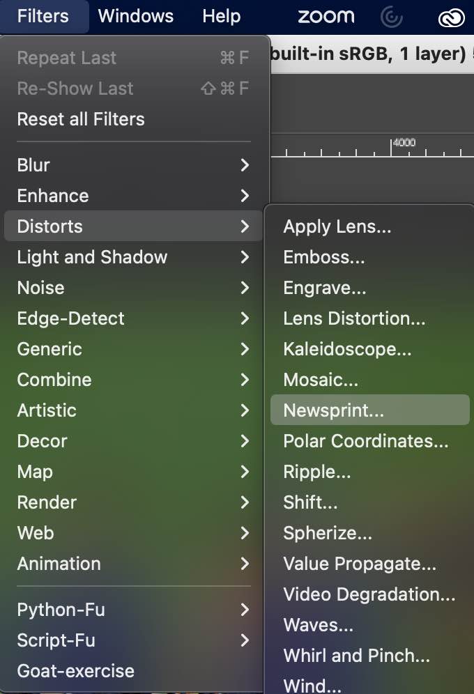
-
utilize line or circle and adjust angle and period accordingly.
-
Before:
-
Final product:
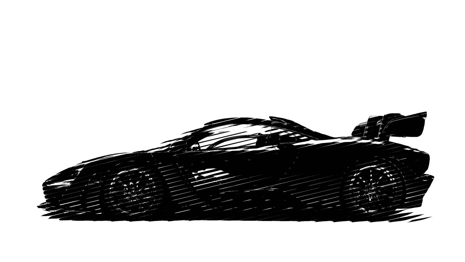
Image Compression
As we are aware, we need to always always compress our images before pushing onto our repo. The three tools that I use are: 1. Xnconvert 2. Imagemagick 3. Default Preview on MacOS
Compressing using xnconvert
xnconvert is very similar to imagemagick, with the difference being that xnconvert has an app while imagemagick is run in the terminal. I am more comfortable with the app interface over the terminal, and therefore prefer xnconvert.
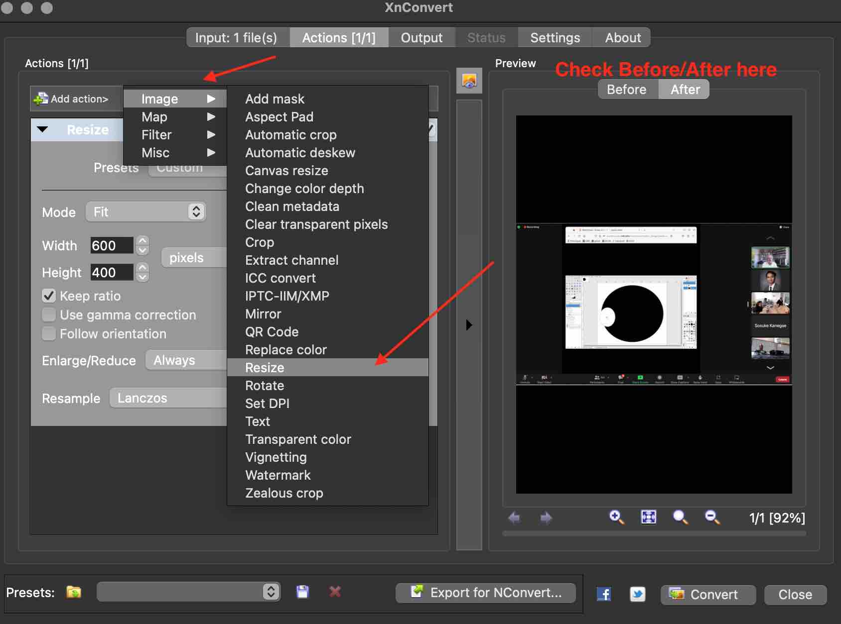
Workflow for compression using xnconvert:
- Input file(s) under the
InputTab - In the
ActionsTab, -> add action -> image -> resize - under
resize, set mode : fit, Width = 600, Height = 400, select (check) Keep Ratio - Under the
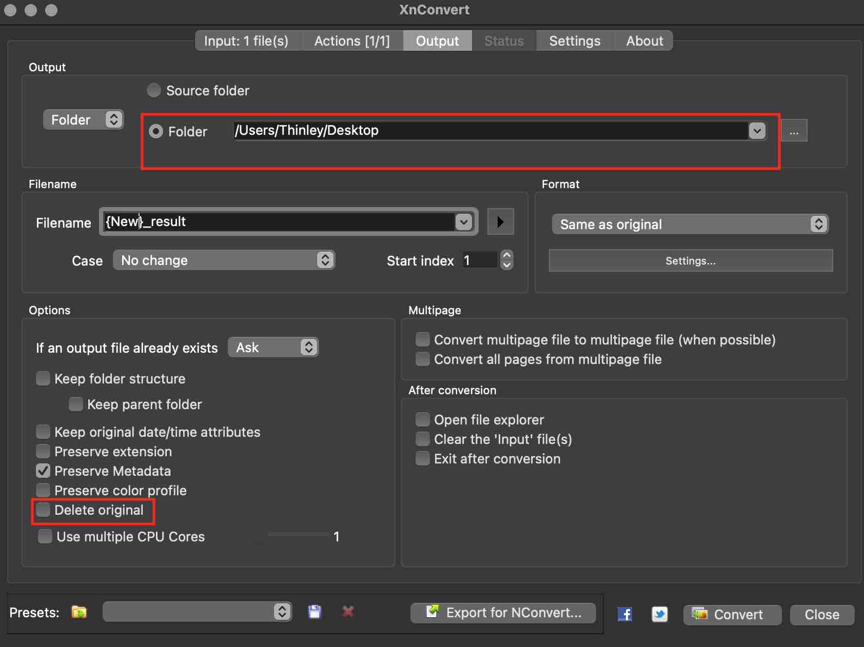
outputtab, you can select new file name, file directory etc. - Hit
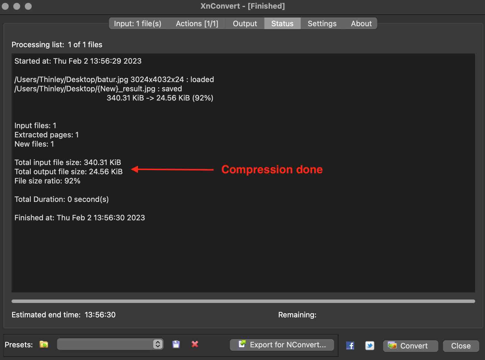
Convertto compress the images and check the sizes understatus
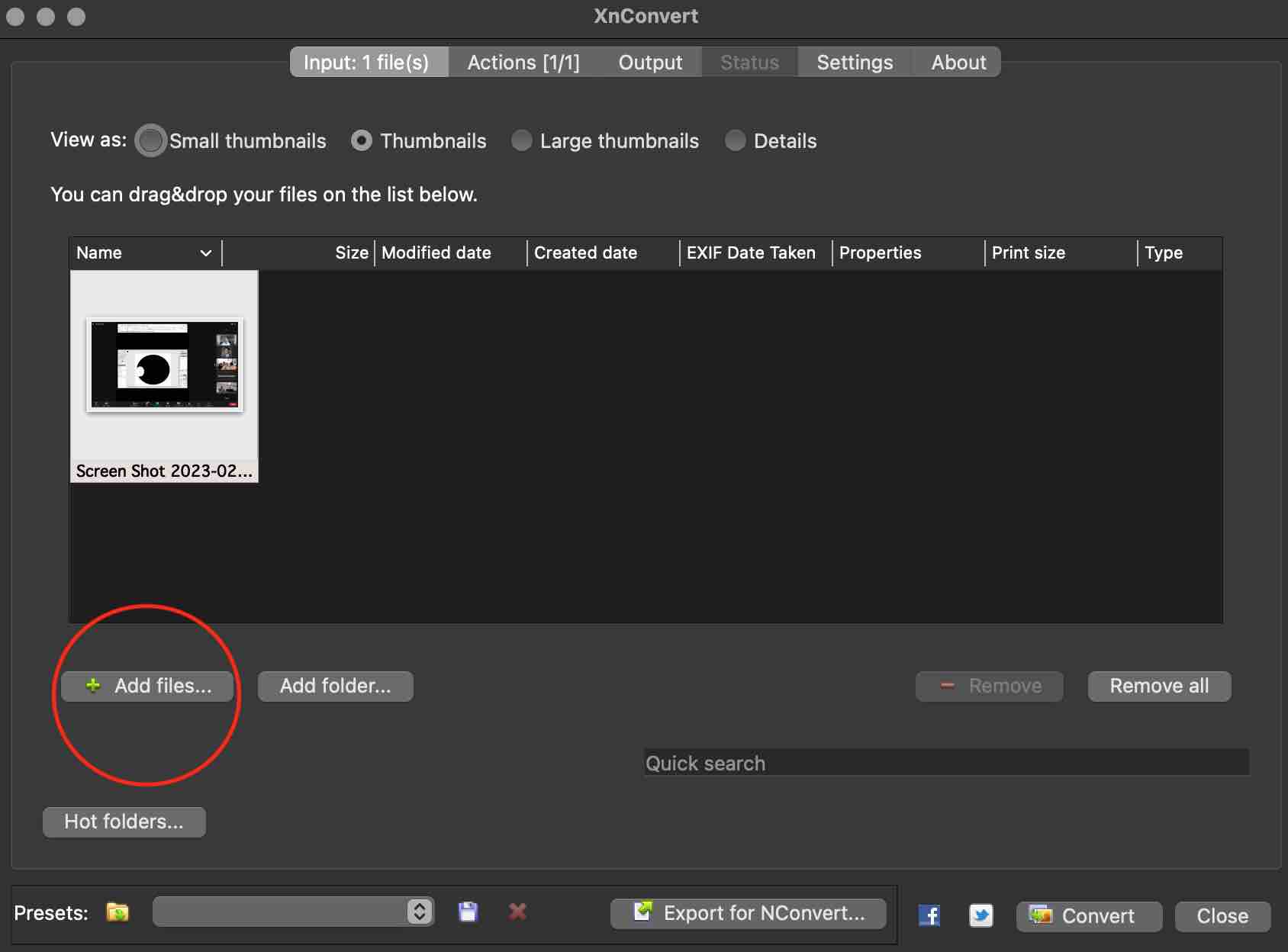
As you can see the compression was successful and it was compressed well!:
Video Compression
I downloaded and installed ffmpeg for my video compression needs and followed a tutorial that I posted above. Linked below is a very important and useful ffmpeg cheat sheet from Professor Neil.
Once download and installation is complete, one can use the codes from the cheat sheet in the terminal.
Just ensure that when you want to compress a video, you are in the directory where the video exists!
To use ffmpeg, first open your terminal and go to the directory. for example if your .mp4 file is in downloads, in terminal:
cd->cd downloadsthen take one of the many codes provided in Neil’s cheat sheet.
for example, I use the no audio:
ffmpeg -i input_video -vcodec libx264 -b:v 1000k -vf scale=-2:1080 -an output_video.mp4
So once you are in the terminal and in the correct directory, paste the above code, replacing input_video with your file name say week2.mp4 and change the output_video to what you want the new file name to be week2compressed.mp4
Your new video can be found in the same directory so for this case downloads.
3D Design
Fusion360
For this weeks assignment, the main 3D designing tool that I used was Fusion360. As fabacademy participants, we all get an education license. To redeem this, first go into Autodesk website and sign in using your email that is linked to Fabacademy by clicking the “forgot my password”. Once login is complete, sign into fusion360 with the same email and you should have “education license” active. If you did not have Fusion360 installed prior to all this, then it can be downloaded from under the Products tab in the Autodesk homepage.
Fusion360 also has a free version under the Hobbyist license incase you do not have access to the education/commercial license.
As for modelling, I decided to create a prototype for the "CommuniBox" final project that I had. I incorporated 2D & 3D design, parameters, Joint Assemblies, external parts insertions, SVG inserts, rendering and animations.
-
To begin, I opened a new project and began sketching the 2D box using the
Sketchfunction.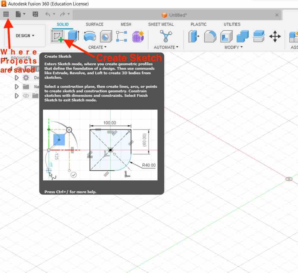
-
In order to parameterize the model so that I created some new user parameters by going to >modify ->
Parameters.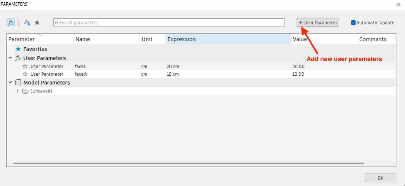
-
Then, I added the parameters to my model by editing the dimensions and calling the user defined values.
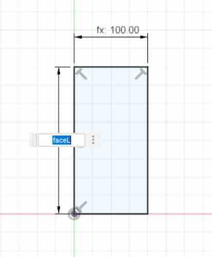
-
After completing the 2D design, I went ahead and
extrudedthe face, to convert the model from 2D to 3D. After which I went ahead and completed the a quarter of the box by sketching and extruding the other faces and also created the door with the same steps.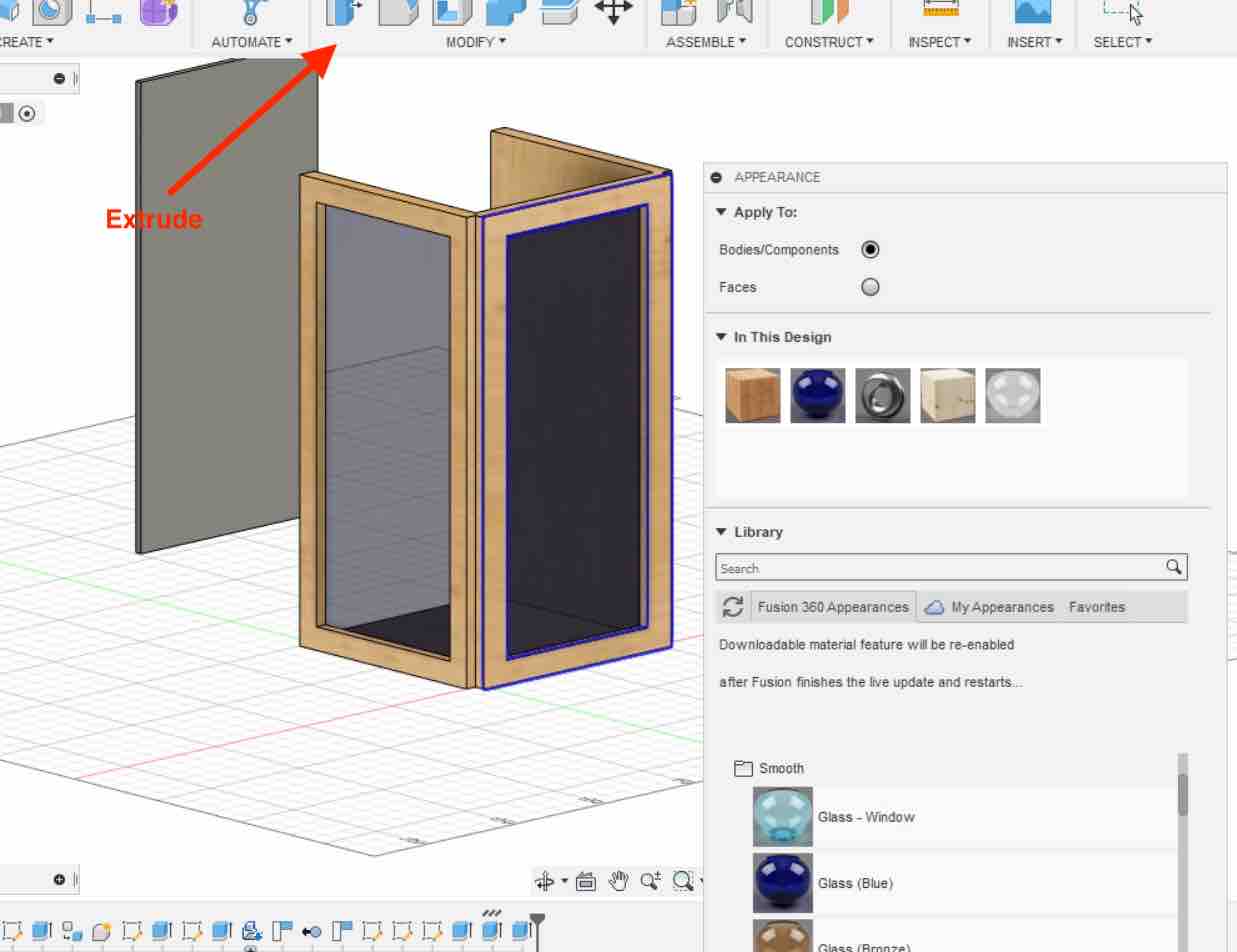
-
I then applied “appearance values” to my model to make it look better. To do this I right-clicked the face of the model and selected
appearance. Once the appearance menu shows up, you can apply the values by dragging and dropping the material/color of your choice. Easy.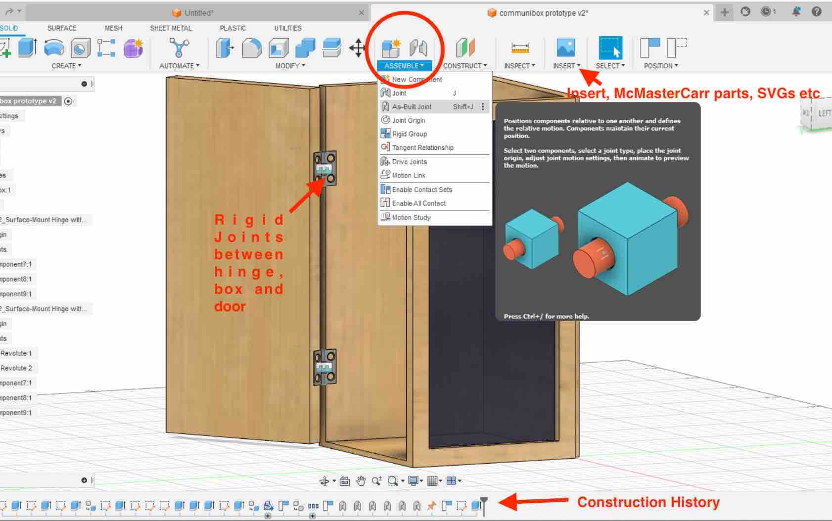
-
Next I wanted to attach the door to the box with the help of a hinge. I inserted a ready made McMaster Carr hinge by going to >
Insert-> insert McMaster Carr part -> search for Hinge -> select a Hinge ->save as STEPThe hinge then showed up in my design.Before assembling joints, its is very important to convert all the
Bodies to Componentssince joints only work on components. To do this, you can go to the bodies tab on the left -> right click ->Create components from bodies.First I created
rigid as-built joints between the hinge, door and the box to fix them. To do this I went to >assembly -> as-built joint -> and selected the door and then the hinge and selectedrigid. Did the same in between the hinge and box as well.Finally to allow the hinge to move like a hinge, I created a
revolute as-builtjoint in the hinge. I followed the same workflow as for the rigid joint, selecting revolute instead of rigid and selecting the hinge arm and then the axis. After this, my door moved like a door. -
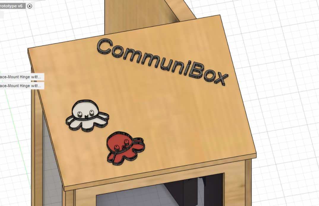
I wanted to create a lid for the box so I went ahead, created a new sketch and created a lid that would fit snug on my box. After that I wanted to play around with the insert svg and insert text feature so I added the following octopus svg (original inspiration) to the top of the lid. Of course I used inkscape to make the the octopus png into a svg.
To add the text and svg, I created a sketch on the lid, and hit insert text and insert svg resectively. Once in my design, I extruded them to my preferred liking and added appearances on them. I then created a joint with a slider behavior between the lid and the box.
-
Video of the door working like a door should I used FFMPEG (no audio code from the cheat sheet) to compress the video:
-
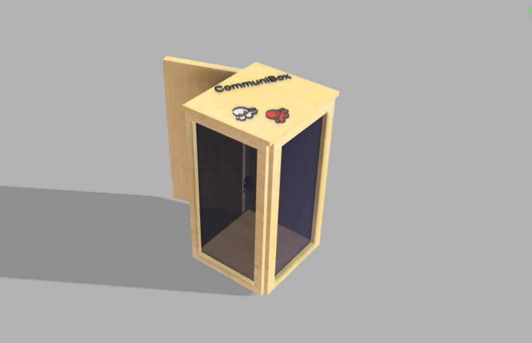
I then explored rendering and animating my model. First I went to
RENDERunder theDesigntab on the top left. There, you an adjust the brightness of the light, the position of the light and much more post processing effects.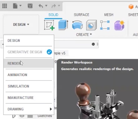
-
Finally, to mess around with the animations, I went under the
Animationunder the sameDesigntab as RENDER. There you will see your model and storyboards with a timestamp on the bottom, since I was a beginner I didn’t do too much but just showed different views of my model. In the storyboard under the model, you can move the the timestamp to increase the time, and once you do that, any angle changes or movement to the model will be recorded as an animation frame. Finally you canpublishthe animation and can select your preferred video ratio.In hindsight, I could’ve “animated” my joints and then recorded my animation.
TinkerCAD
Along with Fusion360, I also decided to learn and work with TinkerCad due to its awesome open source and browser accessibility. I think its especially important for when we have to teach younger students, since the interface is simpler and looks very child friendly as well.
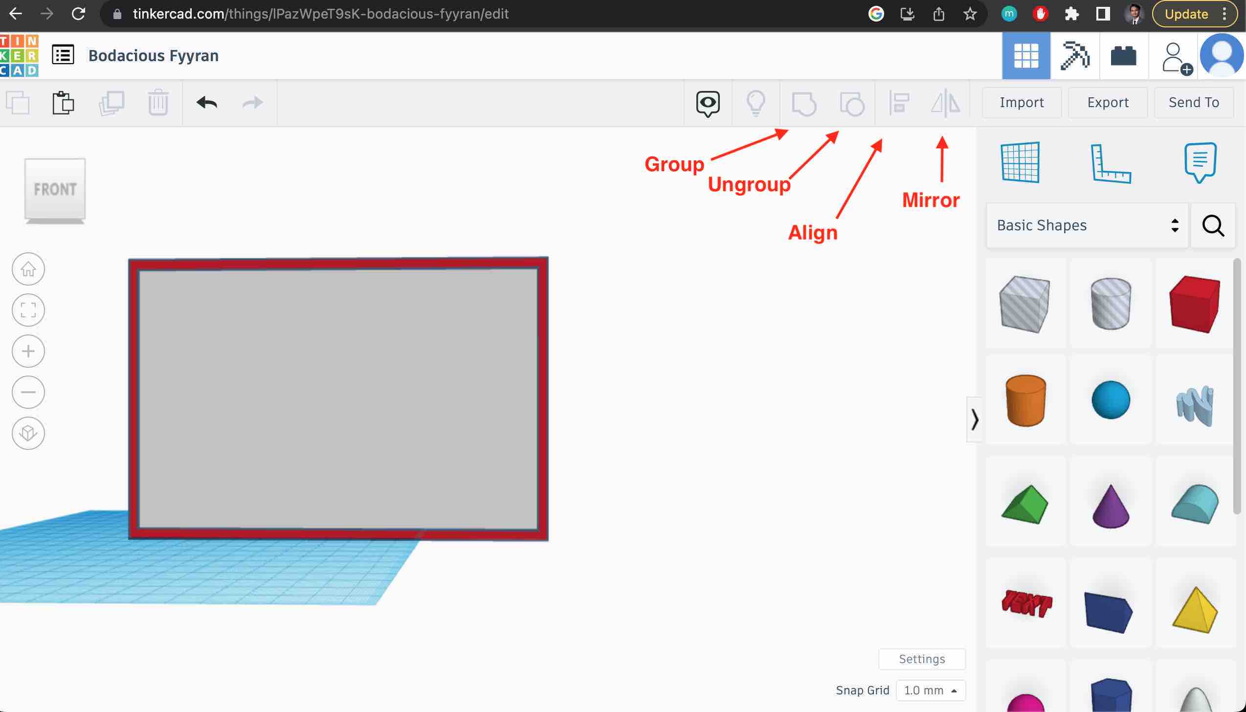
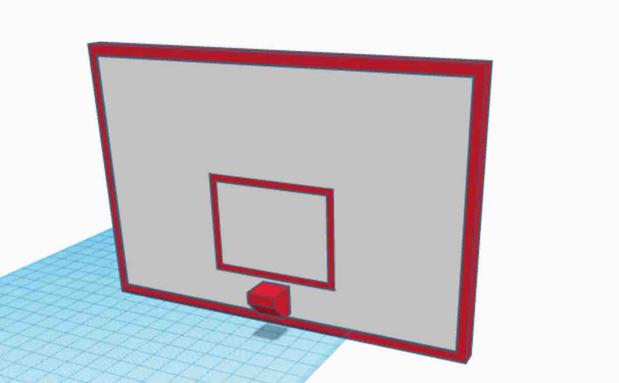
I watched a few tutorials on youtube regarding modelling in TinkerCAD and then decided to model a basketball backboard (one of my final project ideas) by using only the basic shapes.
It was a fun and simple modelling experience and the alignment tool was very useful.
Tips, Notes and Runthrough:
-
To begin, just log in with an email and “create new design”
-
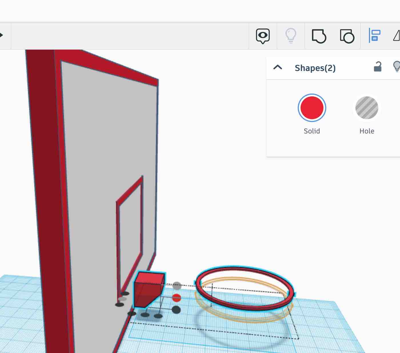
extrusion and cutting works different compared to other modelling softwares where in you need to add a new shape and “group” them to combine them and if you want to cut, you need to add a new shape, select hole, and then group then. This grouping will remove the “hole” shape from your original shape
-
To group, just use shift and select the bodies and hit the group icon on the top right
-
to align, select the two bodies and hit hit the align button on the top right. Then select the body that you want the other object to be aligned first, and then select where you want to align it. There will be many possible alignment points.
Final Result:
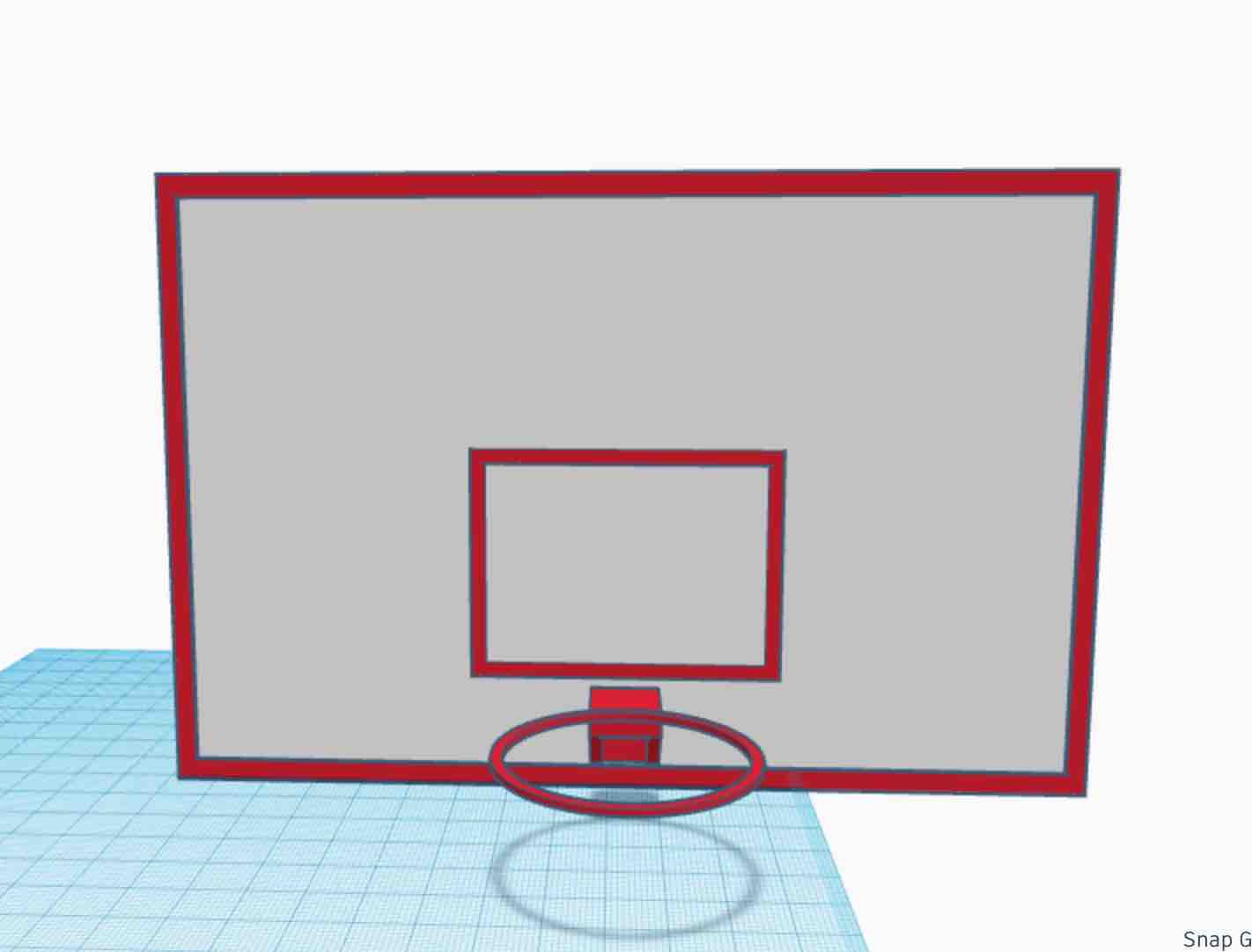
Its very simple! But I wanted to learn the software and wanted to make it somewhat related to one of my final projects! A major drawback of TinkerCAD is the lack of parameterization and constraints
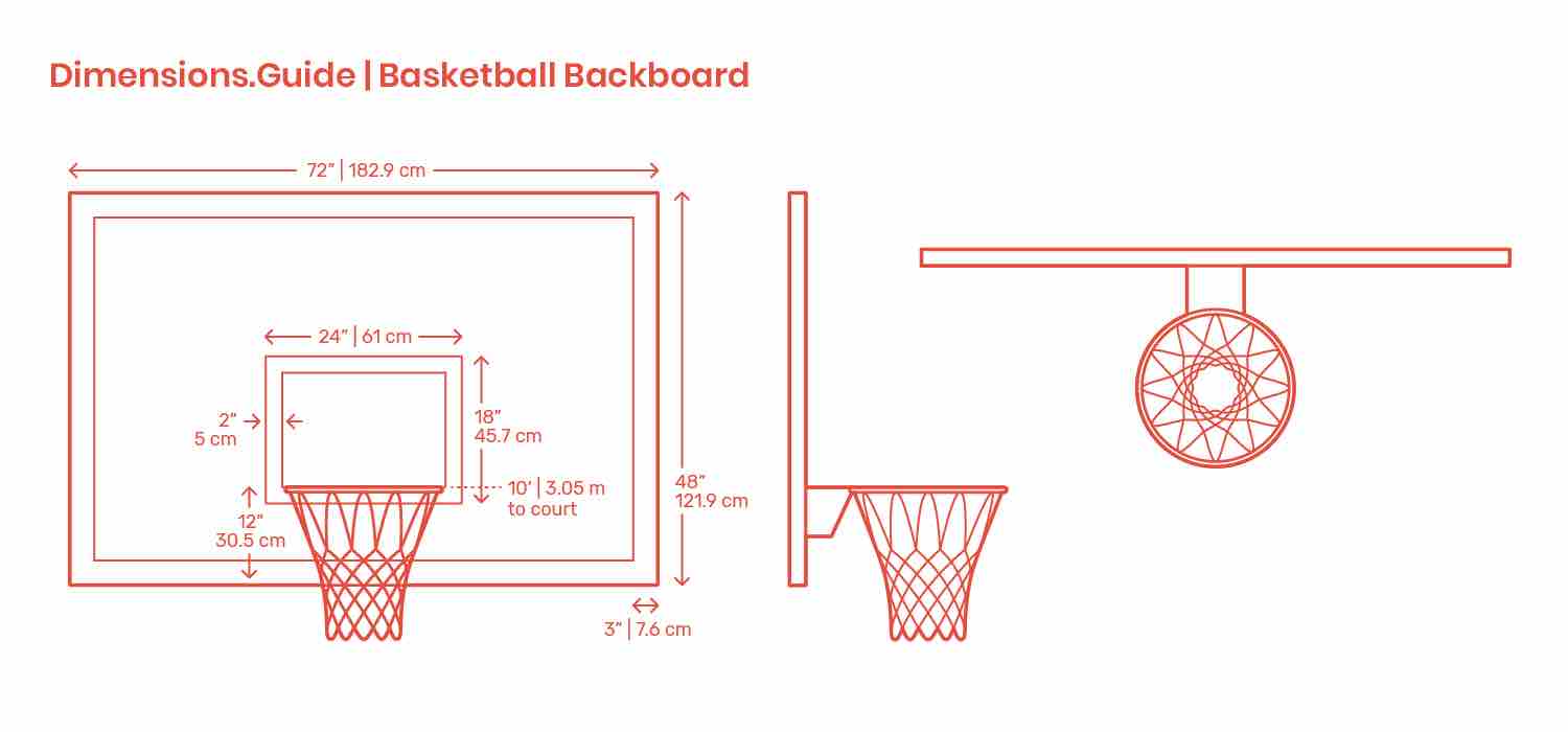
Dimensions reference for the model:
FreeCAD
Along with Fusion360 ad TinkerCAD I also messed around with FreeCAD, especially with the constraints and parameterization functions. Thank you to our remote guru Rico for taking the time to give us a recitation on both FreeCAD and Fusion360.
-
For the FreeCAD tutorial, we worked through three workbenches :
Sketch,Spreadsheet, andparts. To begin, I created a new file and selected theSketchworkbench and created a new sketch, selecting the xy plane. Then I used the polyline ( N looking icon with dots) tool to create a arbitrary looking sketch.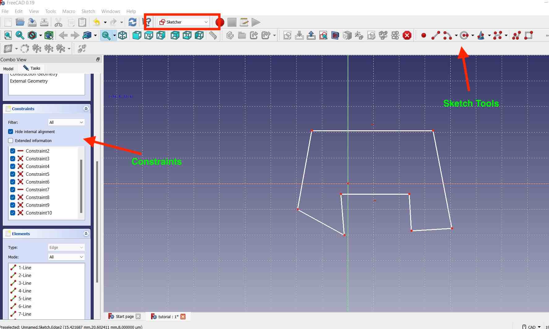
-
Then using the perpendicular, horizontal and vertical constraints from the constraints tool bar, I was able to achieve the following model:
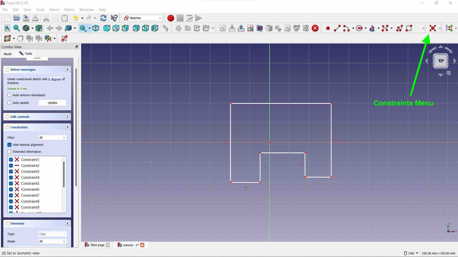
The reason we use ``constraints`` is the reduce the degrees of freedom in a model. You can see in my snippet above that the model has been reduced down to 8 degrees of freedom.
-
Next to work on adding parameters to my designs, I opened the
spreadsheetworkbench, created a new spreadsheet and renamed itparamby double clicking the label option.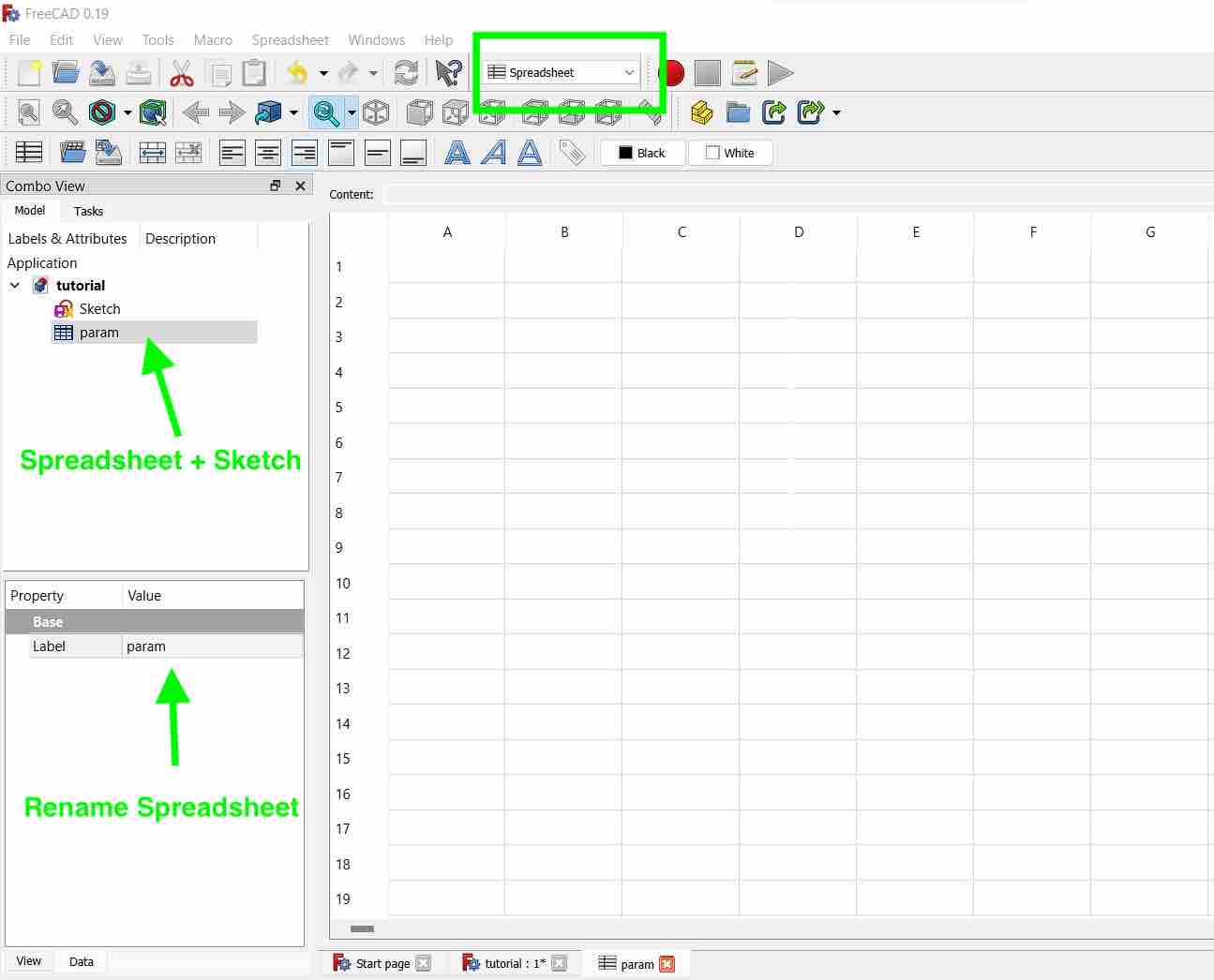
-
Then, I created new parameters, added values and formulae to them respectively. What differs in the parameterization in FreeCAD vs Fusion360 is that you need to create
alias'of the parameters so that they can be called.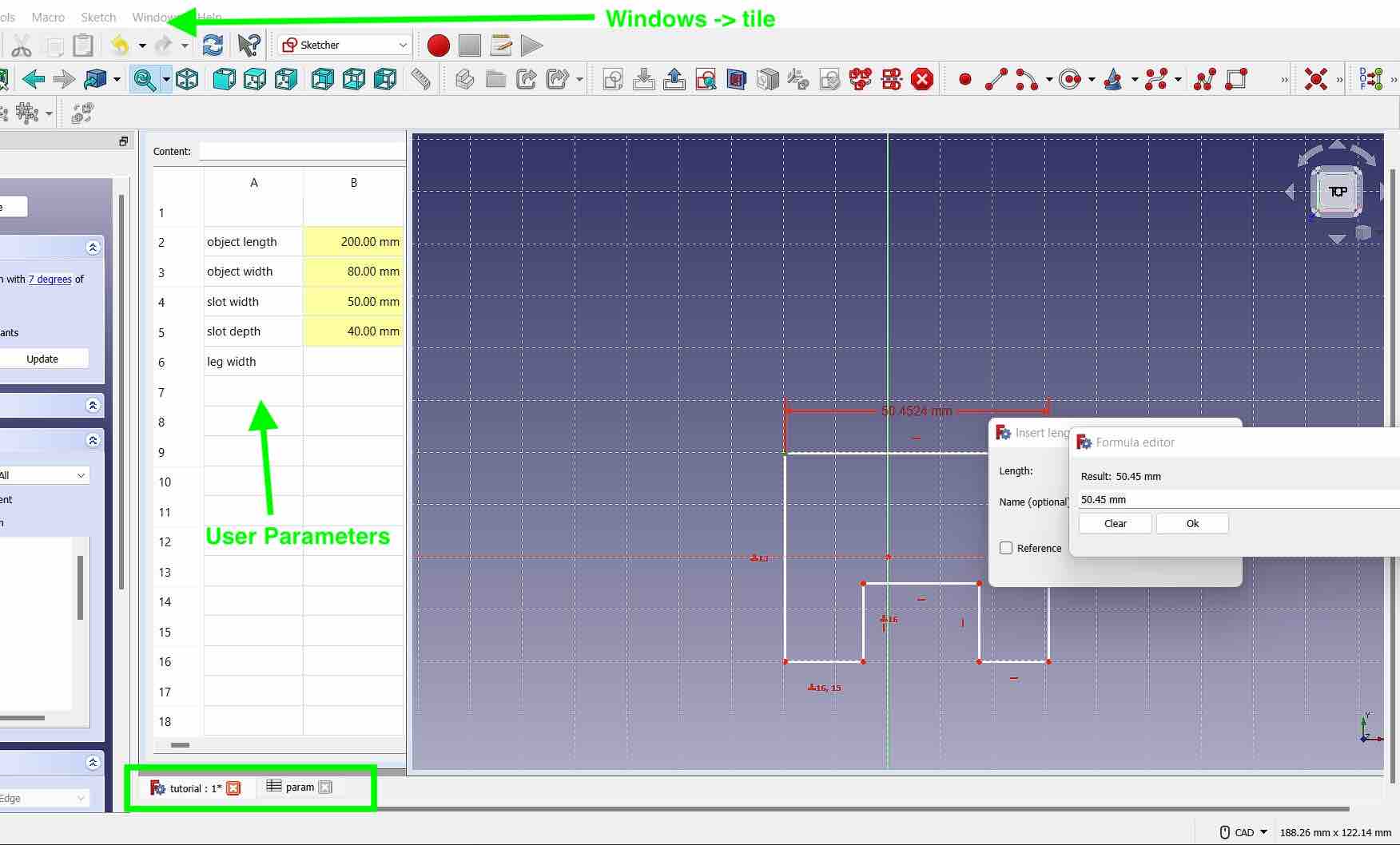
To do this, select the value and enter an alias name on the top of the spreadsheet. If done successfully the cell will turn yellow. To view the spreadsheet and sketch side to side for ease of use. Go to >Windows ->
Tile. -
To assign the parameters to the model. First double click on the sketch in the application tab to go back to the tab. Then from under the
constraintstab, I selected the horizontal sizing constraints and selected the two points to apply them in between. Once the dimension window pops up to input the constraints value, click on the smallfxicon to select a user parameter. In the new pop up window, then you can select the parameter that you want to call from the proper spreadsheet.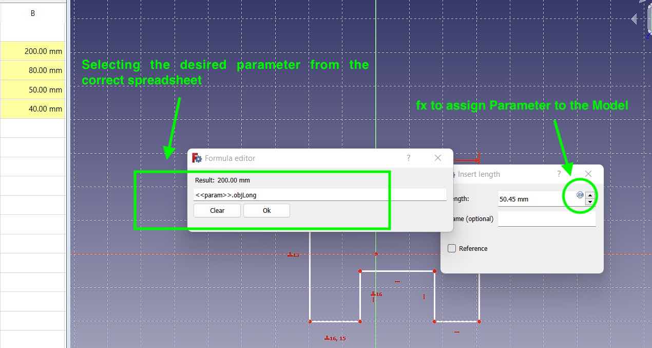
-
After adding all the suer parameters, then finally, I selected the
partworkbench andextrudedthe the sketch to made it into a 3D model. Since the model has constraints and has parameters, I can then just edit one value on the spreadsheet and the entire model will get updated. This allows for less dimension tweaking!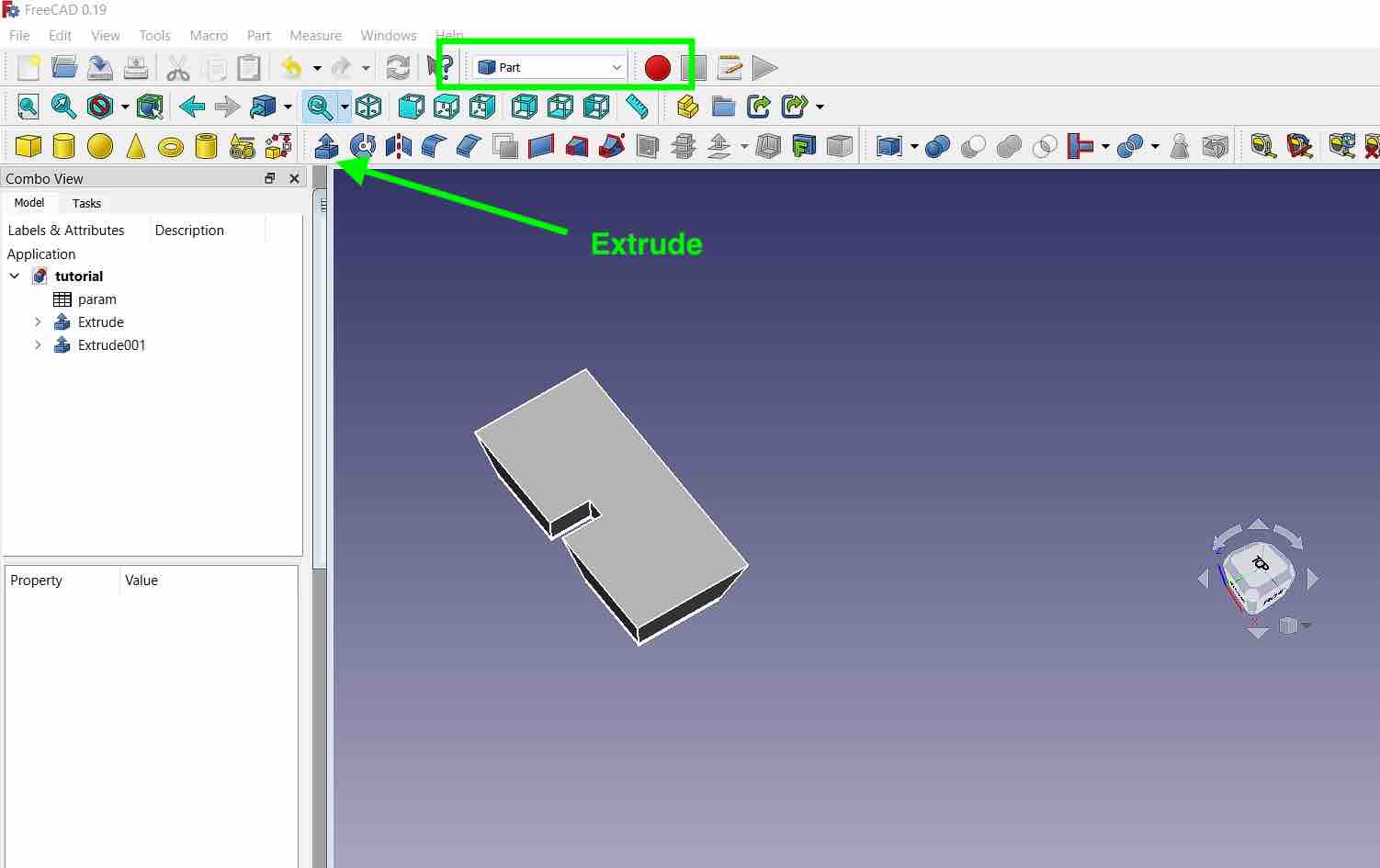 
Issues faced this week:
The main issue I faced this week as when I tried embedding my video on my website during documentation. I am currently using markdown and mkdocs for my documentation and had to use html syntax to embed my video.
Initially I called the following directory path:
src="../videos/week02/Revolute.mp4 type=video/mp4"
And this worked in markdown preview but not on my website. Thanks to Julian, he helped me understand that the html syntax for directories was slightly different and that I had to add an extra ../ to my pathing and it worked.
Finally, the pathing that worked:
src="../../videos/week02/Revolute.mp4 type=video/mp4"