Week 14. Interface and Application Programming
Group Assignment link:
Individual Assignment
This week we are exploring on how we can interact with our micro controller boards using an application or on how we can interface and interact with the data from our board (especially visualization). The lecture was a bit overwhelming with professor Neil explaining a lot of tools, programs and applications we could use for the week and it seemed very programming heavy. As soon as I saw Nadieh’s examples on visualization, I was inspired to do something similar on a much smaller scale. I wanted to visualize the data received from turning a potentiometer. I did not know where to start and again like I mentioned it was pretty overwhelming. Luckily, Rico gave us a very helpful practical recitation on Processing.
Processing is a language and integrated development environment through which one can produce visual and interactive media. For what I wanted to do for the week, Processing seemed perfect. If you are uncomfortable with Processing’s IDE, one can also integrate it with visual studio code and use that environment to edit and run the code.
Processing
First I began with downloading Processing since I already had Microsoft Visual Studios downloaded. This GIT resource was very helpful in integrating Processing with Visual Studios Code. After downloading Processing, I opened the app and went to tool- > Install processing-java. Parallely, I also opened Visual Studios and installed Processing Language by Avin Zarlez.
For the tutorial Rico gave us, we used the Processing IDE itself so I am going to leave visual studios on the back burner for now and work on just Processing IDE and Arduino IDE.
In Processing, we began with setting up the following block:
    void setup()
    {

    }
    void draw()
    {

    }
Under void setup, you put all the functions you want to run once. for this case, like the size of the pop up window etc. whereas under void draw you put functions that you want to run repeatedly.
Some tips and functions for processing:
Under void setup():
* size(x,y) =creates a canvas size of x pixels wide and y pixels tall
* noCursor() removes the traditonal white cursor in the canvas window
Under Void Draw:
* In processing, the origin of most objects is on the Top left, so (0,0) is in the top left so x increases going right and y increases going down.
* background(R,G,B) shows the color of the background in RGB coding. You can add a fourth value to control transparency.
* noStroke() removes outline
* stroke(R,G,B) stroke color, again RGB
* strokeWeight(#)for the outline stroke thickness
* rect(x position,y position, width, height) Create a rectangle with the origin (top left) is the first two values and the width and height is the second two numbers
* rectMode(CENTER) to auto center the rectangle without having to compensate.
* fill(R,G,B) fill rectangle/shape with the RGB color
* circle(x pos, y pos, size) creates a cicle with its center at x,y and then its size
* textSize(x) sets the size of the text
* text("xyz",pos x, pos y) create text with whats in the quotes at position x,y
* To create a new mouse pointer in the canvas: circle(mouseX,mouseY,20) creates a circle cursor in the canvas
Processing as the Receiver
A very simple workflow: Run the Arduino code and then the Processing!
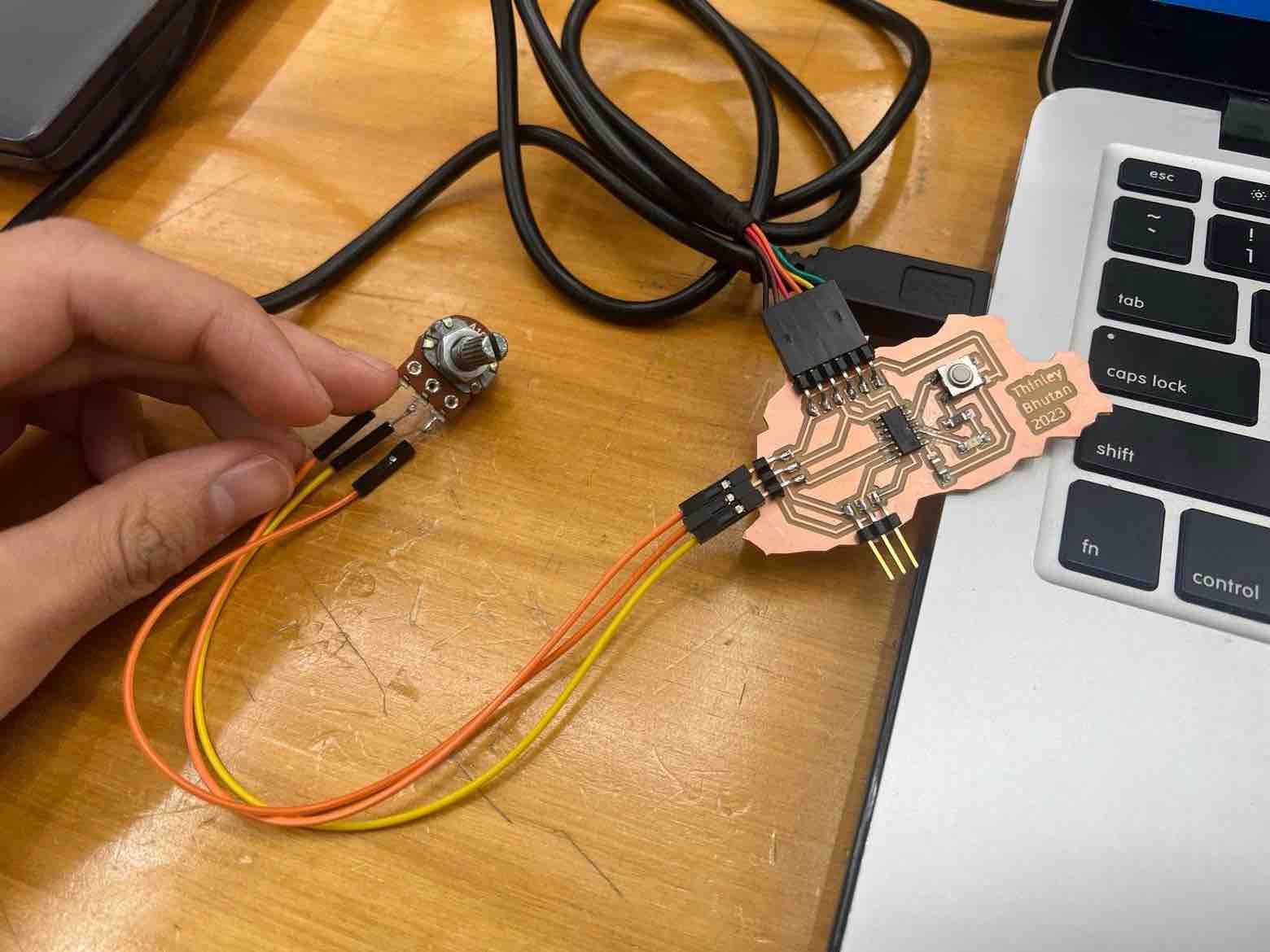
I connected my
Bhutan board to a potentiometer since I wanted to output the data I received from the potentiometer. This is my code for the arduino side to read the potentiometer value.
Code:
    void setup() {
    Serial.begin(9600);
    }
    void loop() {
    int variable1 = int(random(100));
    //int potVal = analogRead(pinNo)

    Serial.println(variable1);


    delay(100);
    }
very simple!.
Now on the processing side.
For my first processing attempt, I took Rico’s tutorial code and edited it so that the when I turned the knob on the potentiometer, the bar graph will increase/decrease based on which direction the potentiometer is turned.
Code:
    //Visualizing Data in Processing from Arduino
    //by Programming for People https://www.youtube.com/watch?v=NhyB00J6PiM
    //refactored by Rico Kanthatham, Skylabworkshop 2023

    import processing.serial.*; //serial library for processing

    Serial bhutanSerial; //define variable for a serial object

    String myString = null; //specify incoming data as string type
    int nl = 10; //ASCII code for carriage return. nl = end of the line
    float myVal; //a floating point variable. converts the string to numbers

    void setup() {
    size(800, 800); //define canvas size

    String myPort = Serial.list() [1]; //Specify which communication (COMM) port it should listen to
    bhutanSerial = new Serial(this, myPort, 9600); // new=make a new connection. this is aways this. myPort specifies the port. 9600: baud rate
    }

    void draw() {

    while (bhutanSerial.available() > 0) {
    myString = bhutanSerial.readStringUntil(nl);

    if (myString != null) {
    background(0,69,69);
    myVal = float(myString); //takes data from serial and turns it into number

    myVal = myVal/100 * height; //scale data to canvas height
    rect(width/2, height-(myVal/2),100,myVal);
    println(myVal);
    }
    }
    }
Highlight features of the code:
    void setup()
    {
    size(800, 800); //define canvas size

    String myPort = Serial.list() [1]; //Specify which communication (COMM) port it should listen to
    bhutanSerial = new Serial(this, myPort, 9600);
This is the main line of code which pulls the data from the Serial monitor of the Arduino.
As long as there is incoming data, the graph will be activated.
Attempt 2: Circle Population
I wanted to play around more with Processing so I wanted to make something visually interesting. The potentiometer to board connection and the Arduino code will remain the same just a difference in the Processing code.
The idea is that the the canvas will be very lightly populated with light red colored circle and when the knob on the potentiometer is turned, the canvas will be more densely populated with red circles (some darker in color).
I received help from ChatGPT for the code.
Code:
    import processing.serial.*;

    Serial serialPort;              // Serial port object
    int circleCount = 0;            // Variable to store the number of circles to draw
    ArrayList<Circle> circles = new ArrayList<Circle>();   // Array to store the circles

    void setup() {
    size(500, 500);   // Set the size of the window
    smooth();          // Enable anti-aliasing for smoother circles
    String myPort = Serial.list() [1];
    serialPort = new Serial(this, myPort, 9600);   // Replace "COM3" with the port name of your Arduino
    }

    void draw() {
    background(255);   // Clear the screen with white

    // Draw the circles
    for (int i = 0; i < circleCount; i++) {
    Circle c = new Circle();
    circles.add(c);
    c.draw();
    }

    // Remove the circles that have faded out completely
    for (int i = circles.size() - 1; i >= 0; i--) {
    if (circles.get(i).alpha == 0) {
    circles.remove(i);
    }
    }

    if (serialPort.available() > 0) {   // Check if there is data in the serial buffer
    int sensorValue = serialPort.read();   // Read the data from the serial port
    circleCount = int(map(sensorValue, 0, 1023, 0, 101));   // Map the sensor value to the number of circles to draw
    if (circleCount == 0) {   // Ensure that there are no circles drawn if the sensor value is zero
    circles.clear();
    }
    }
    }

    class Circle {
    float xPos, yPos, size, alpha;

    Circle() {
    xPos = random(width);
    yPos = random(height);
    size = random(10, 50);
    alpha = 255;
    }

    void draw() {
    fill(255, 0, 0, alpha);
    ellipse(xPos, yPos, size, size);
    alpha -= 2;
    }
    }
Arduino, Javascript and Johnny-five
I was recommended to work on controlling an arduino, especially a servo or a bldc, with JavaScript and Johnny-five. The firmata protocol allows for an MCU to be controlled by external applications from your computer. Johnny-five is a user friendly robotics library for Javascript. The firmata protocol will be uploaded through the Arduino IDE and USB.
I began with first downloading Node.js. I just went to the website and downloaded the recommended version for my computer. Then the next steps were to download Johnny-five libraries and the KeyPress functionality. This will be done using npm in the terminal.
Steps:
1. Open your terminal and type npm init. Hit yes to everything and then enter at the final “is this okay”
2. in the terminal, type npm install johnny-five and hit enter. the installation will begin
3. in the terminal, type npm install keypress
Keypress is needed for my case since I want to use the arrow keys to control the throttle of my esc. This is all for the set up.
Next is the connection, I used a 1400KV motor, 30A ESC and a 3S 2200mah Lipo and Arduino Mega. I followed the following connection obtained from the Johnny-five website:
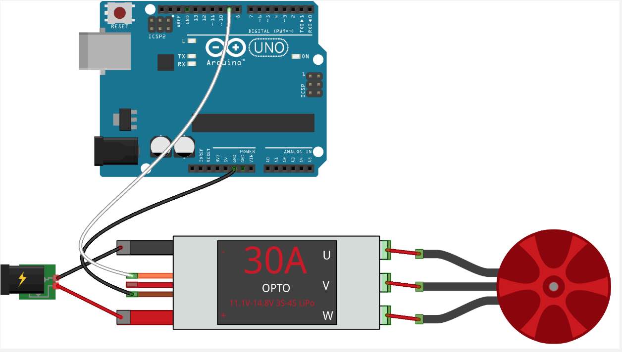
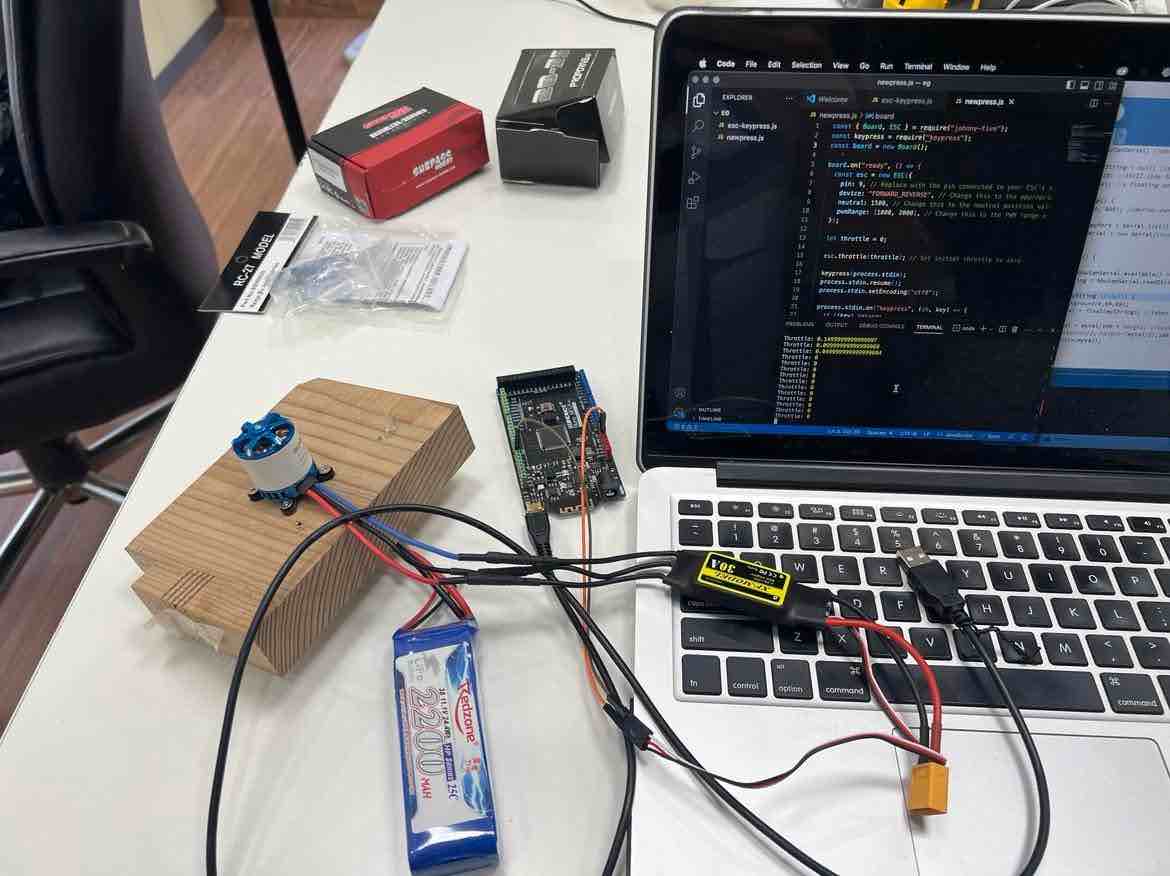
Then after setting up all the wiring, I connected the Mega to my computer.
After setting up the software and the hardware now we go into the programming side of things.
In the arduino IDE, go to file->examples->firmata->StandardFirmataPlus.
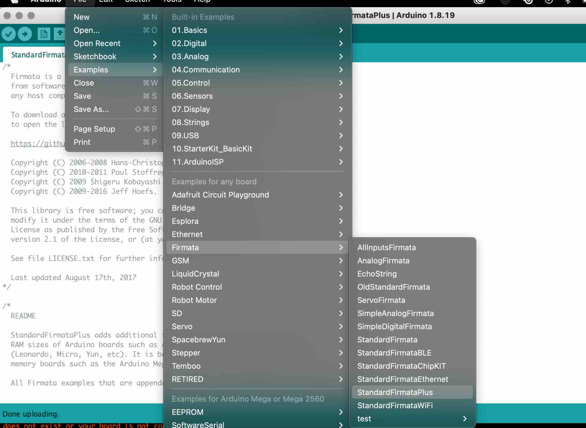
Once the standardfirmataplus sketch is opened, upload the code to the board. Then open up Visual Studios and there, create the .js code that will allow for the motor to be controlled by the keypad.
Here is my .js code:
    const { Board, ESC } = require("johnny-five");
    const keypress = require("keypress");
    const board = new Board();

    board.on("ready", () => {
    const esc = new ESC({
    pin: 9,
    device: "FORWARD_REVERSE",
    neutral: 1500,
    pwmRange: [1000, 2000],
    });

    let throttle = 0;

    esc.throttle(throttle);

    keypress(process.stdin);
    process.stdin.resume();
    process.stdin.setEncoding("utf8");

    process.stdin.on("keypress", (ch, key) => {
    if (!key) return;

    if (key.name === "up") {
    throttle += 0.05;
    if (throttle > 1) throttle = 1;
    console.log("Throttle:", throttle);
    esc.throttle(throttle * (esc.pwmRange[1] - esc.pwmRange[0]) + esc.pwmRange[0]);
    } else if (key.name === "down") {
    throttle -= 0.05;
    if (throttle < 0) throttle = 0;
    console.log("Throttle:", throttle);
    esc.throttle(throttle * (esc.pwmRange[1] - esc.pwmRange[0]) + esc.pwmRange[0]);
    }
    });
    });
The code was initially taken from the Johnny-five example and then edited with some help from ChatGPT.
RUNNING THE CODE: Finally, to upload and run the .js code, in the terminal, type: node nameofthecode.js. once this is done, the code will run and if all goes well, you should be able to control the throttle (increase with up key, decrease with down key) using your computer’s arrow keys.
Working:
[SOUND ON Please]
Design Files
Processing:
Arduino:
Javascript: