The programming
After design and production of the Transmitter and Receiver boards, I moved on to the programming side of things, for communication between the two.
In the Arduino IDE, I ensured that I had downloaded the three crucial libraries for both sets of codes. They are:
Receiver
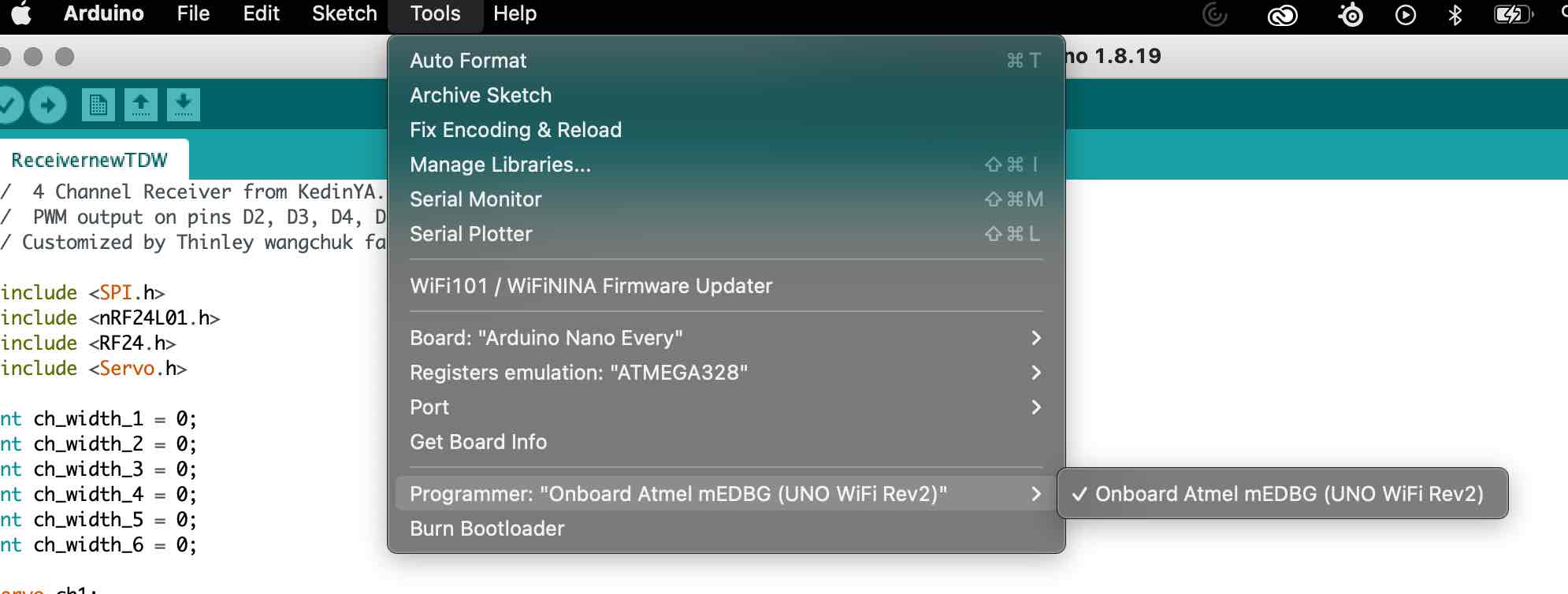
I began with the Receiver. since I was working with the arduino nano every, I had to download the correct board for it. In the board manager, I went ahead and installed the megaAVR board manager.
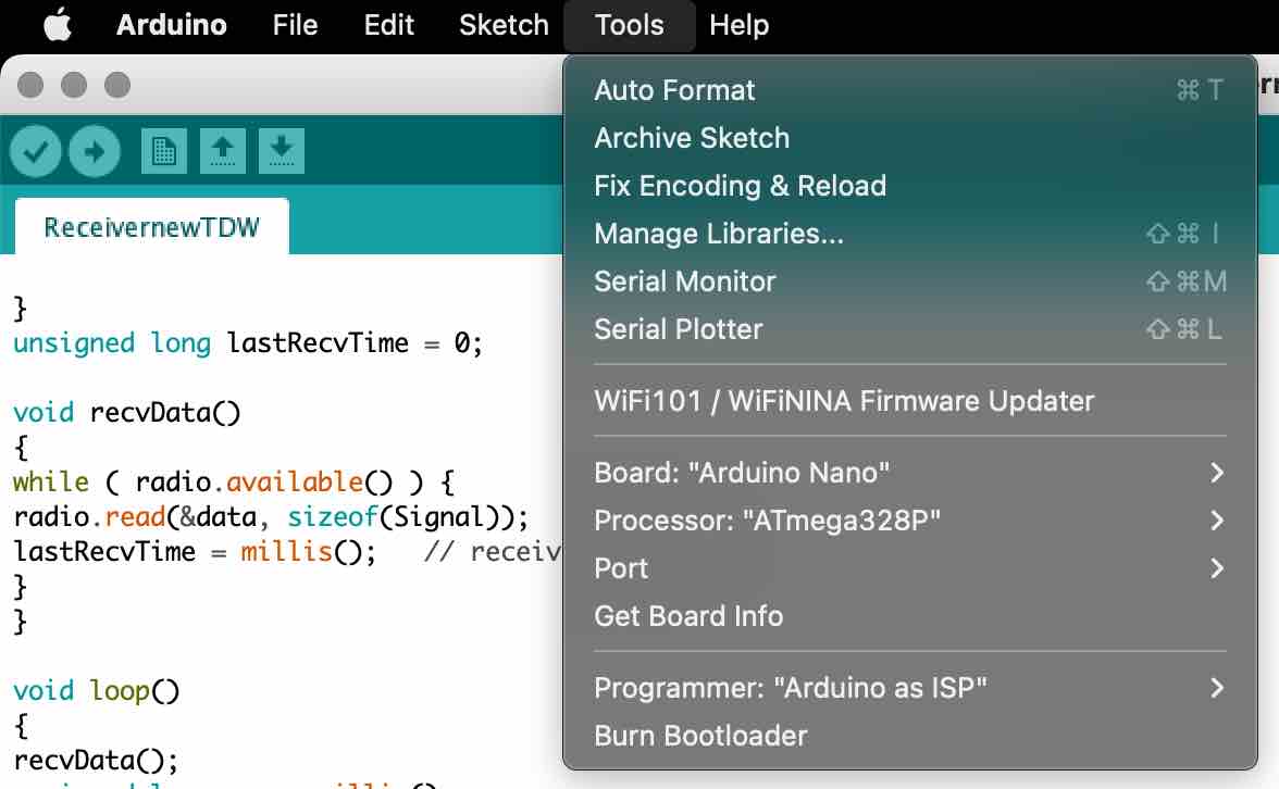
Then in the tools, I selected my board to be the Arduino Nano Every. Here are the other settings:
Programming the receiver is quite straight forward since I am using the arduino nano and it has inbuilt micro usb port.
the code:
//  6 Channel Receiver from KedinYAP.
// Customized by Thinley wangchuk fabacademy 2023 (into 6 channels)
//  PWM output on pins D2, D3, D4, D5, D6, D7

#include <SPI.h>
#include <nRF24L01.h>
#include <RF24.h>
#include <Servo.h>

int ch_width_1 = 0;
int ch_width_2 = 0;
int ch_width_3 = 0;
int ch_width_4 = 0;
int ch_width_5 = 0;
int ch_width_6 = 0;

Servo ch1;
Servo ch2;
Servo ch3;
Servo ch4;
Servo ch5;
Servo ch6;

struct Signal {
byte throttle;
byte pitch;
byte roll;
byte yaw;
byte aux1;
byte aux2;
};

Signal data;

const uint64_t pipeIn = 0xE9E8F0F0E1LL;
RF24 radio(9, 10);

void ResetData()
{
// Define the initial value of each data input
// The middle position for Potenciometers. (254/2=127)
data.throttle = 0; // Motor Stop
data.pitch = 127;  // Center
data.roll = 127;   // Center
data.yaw = 127;   // Center
data.aux1 = 127;   // Center
data.aux2 = 127;   // Center
}


void setup()
{
//Set the pins for each PWM signal |
ch1.attach(2);
ch2.attach(3);
ch3.attach(4);
ch4.attach(5);
ch5.attach(6);
ch6.attach(7);

//Configure the NRF24 module
//  ResetData();
//  radio.begin();
//  radio.openReadingPipe(1,pipeIn);
//
//  radio.startListening(); //start the radio comunication for receiver
//}

//Configure the NRF24 module
ResetData();
radio.begin();
radio.openReadingPipe(1,pipeIn);
radio.setAutoAck(false);
radio.setDataRate(RF24_250KBPS);
radio.setPALevel(RF24_PA_HIGH);
radio.startListening(); //start the radio comunication for receiver

pinMode(6,OUTPUT);

}
unsigned long lastRecvTime = 0;

void recvData()
{
while ( radio.available() ) {
radio.read(&data, sizeof(Signal));
lastRecvTime = millis();   // receive the data
}
}

void loop()
{
recvData();
unsigned long now = millis();
if ( now - lastRecvTime > 1000 ) {
ResetData(); //
}

ch_width_1 = map(data.throttle, 0, 255, 1000, 2000);     // pin D2 (PWM signal)
ch_width_2 = map(data.pitch,    0, 255, 1000, 2000);     // pin D3 (PWM signal)
ch_width_3 = map(data.roll,     0, 255, 1000, 2000);     // pin D4 (PWM signal)
ch_width_4 = map(data.yaw,      0, 255, 1000, 2000);     // pin D5 (PWM signal)

ch_width_5 = map(data.aux1,     0, 255, 1000, 2000);     // pin D6 (PWM signal)
ch_width_6 = map(data.aux2,     0, 255, 1000, 2000);     // pin D7 (PWM signal)


// Write the PWM signal
ch1.writeMicroseconds(ch_width_1);
ch2.writeMicroseconds(ch_width_2);
ch3.writeMicroseconds(ch_width_3);
ch4.writeMicroseconds(ch_width_4);
}
One of the most important lines in this code is the const uint64_t pipeIn = 0xE9E8F0F0E1LL; line because the constant needs to be the same for both the receiver and transmitter inorder to establish successful communication.
Transmitter
Programming the transmitter was a bit tricker since it was a custom board made by me and I had to do a lot of research on burning the bootloader and programming the atmega328p chip. Before programming the atmega328p chip, its bootloader needs to be burnt, just an extra step to keep in mind.
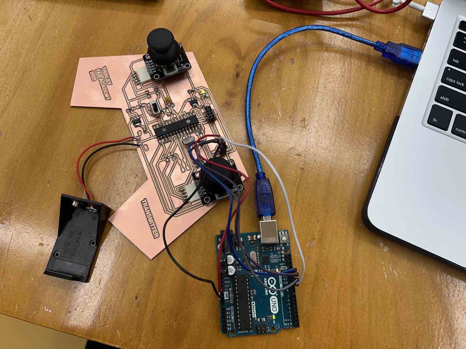
I used an external Arduino uno dev board to program my transmitter (atmega328p) using the ISP.
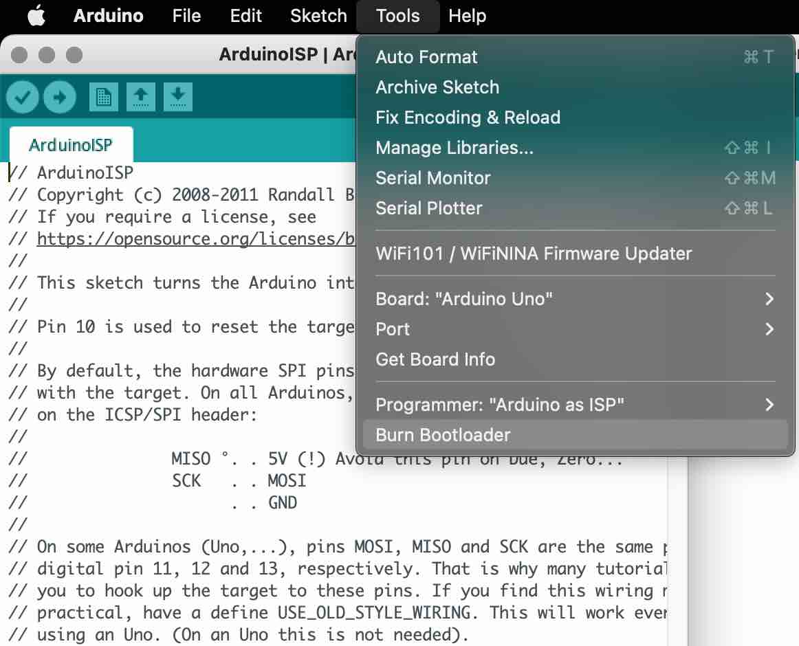
First, I opened the ArduinoISP code from under examples and uploaded the code to the Arduino Uno (the programmer). I waited for the upload to finish.
Then, I followed the following diagram to connect my board (target) to the arduino:
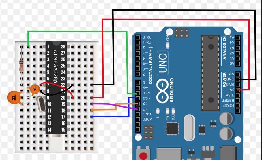
Then in the Arduino IDE, under tools select the board -> Arduino Uno, select the correct COM port, programmer -> arduino as ISP and then I hit burn bootloader found under the tools section.
This will take a bit. the IDE will tell you when its done burning. Your custom board with the ATMGEA328p is now burnt.
Next to upload the transmitter code, first I opened the code and edited for how I want my code to run. This included adding more channels, defining the initial values of the potentiometers, attaching the channels, setting the correct pins which were linked to throttle, pitch, roll and yaw, and ensuring proper direction of the joystick was set (up to increase throttle, down to decrease).
Then, I changed the board to nano, processor to atmega328p, the correct port and kept Arduino as ISP.
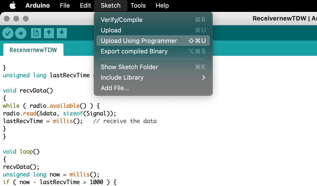
The final step is the most crucial. After compiling your code as usual, do not upload using the typical upload button as is usually done. Instead, I went to Sketch and selected Upload using programmer. This will upload the code to your board using the arduino Uno without the code uploading to the Uno.
I successfully burnt my boards’ boot loader and succesfully uploaded the code.
the code:
// original code:4 Channel Transmitter by KendinYap
// Customized and edited by Thinley Wangchuk Fabacademy 2023
// 6 Channels

#include <SPI.h>
#include <nRF24L01.h>
#include <RF24.h>

const uint64_t pipeOut = 0xE9E8F0F0E1LL;   //IMPORTANT: has to be the same as in the receiver 0xE9E8F0F0E1LL
RF24 radio(9, 10); // select CE,CSN pin

struct Signal {
byte throttle;
byte pitch;
byte roll;
byte yaw;
byte aux1;
byte aux2;
};

Signal data;

void ResetData()
{
data.throttle = 0; // Motor Stop (254/2=127)| Motor (Signal lost position )
data.pitch = 127; // Center  (Signal lost position)
data.roll = 127; // Center  (Signal lost position )
data.yaw = 127; // Center  (Signal lost position)
data.aux1 = 127;    // Center (Signal lost position)
data.aux2 = 127;    // Center (Signal lost position
}

void setup()
{
//Start everything up


radio.begin();
radio.openWritingPipe(pipeOut);
radio.setAutoAck(false);
radio.setDataRate(RF24_250KBPS);
radio.setPALevel(RF24_PA_HIGH);
radio.stopListening(); //start the radio comunication for Transmitter
ResetData();

}

void loop()
{

/*If your channel is reversed, just swap 0 to 255 by 255 to 0 below
EXAMPLE:
Normal:    data.ch1 = map( analogRead(A0), 0, 1024, 0, 255);
Reversed:  data.ch1 = map( analogRead(A0), 0, 1024, 255, 0);  */

/* The two channels to which the servos are linked to may need their Analog input pin declarations swapped for the correct roll directions.
Such as "(A1)" being swapped with "(A0)" or vice versa, all below.*/

data.throttle = map( analogRead(A3), 0, 1024, 0, 255 );
data.roll = map( analogRead(A1), 0, 1024, 0, 255 );
data.pitch = map( analogRead(A0), 0, 1024, 0, 255 );
data.yaw = map( analogRead(A2), 0, 1024, 0, 255 );

data.aux1 = map( analogRead(A6), 0, 1024, 0, 255);
data.aux2 = map( analogRead(A7), 0, 1024, 0, 255 );
radio.write(&data, sizeof(Signal));
}
Works !
After much debugging, here is my transmitter and receiver communicating and working:
Useful video for the above: burn ATMEGA328p bootloader
Spiral 2 Receiver
With my own Receiver board done, I wanted to test if my custom transmitter communicates with my new custom receiver.
To program the receiver, I used the same code as above, and I used an Arduino Uno to program the receiver using the AVRISP.
My custom board works!:
I then installed my receiver board into my RANGER2000 RC Drone to test it out and it works!