Design and Manufacturing
For my 3D designing and modelling, I will be predominantly using Fusion360. For making the Drone design cutable, I will be using Rhino to convert 3D to 2D and will be using XFLR5 For aerodynamic analysis for my wing’s airfoil.
The Transmitter Case:
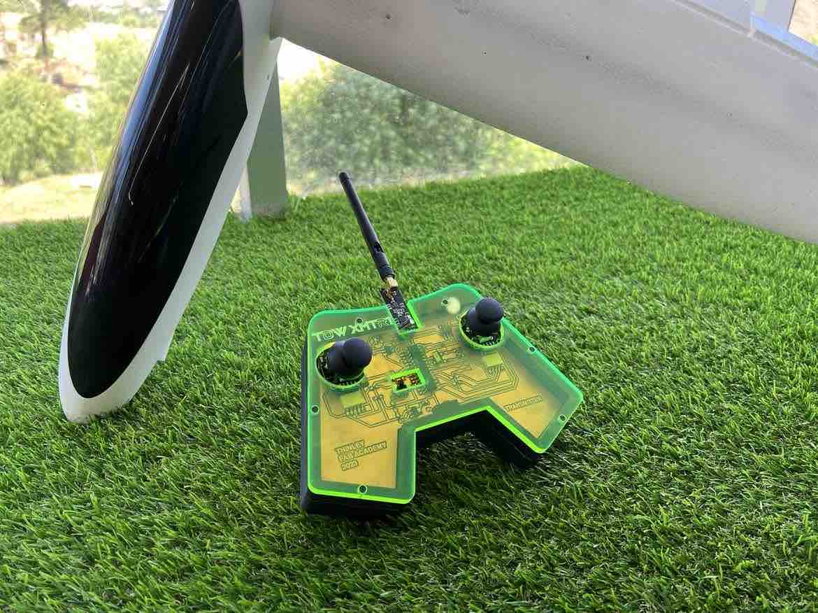
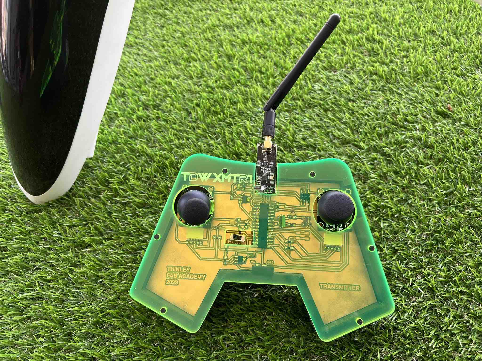
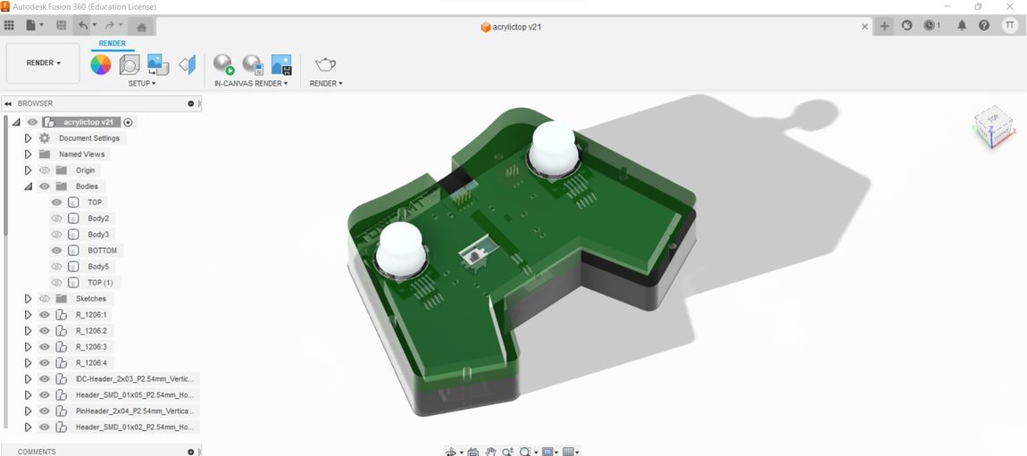
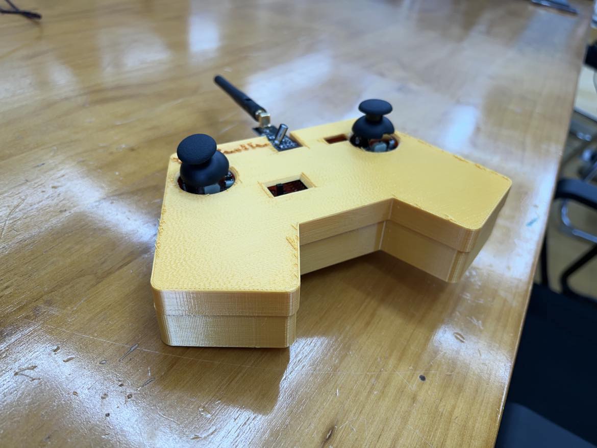
HERO RENDER:
Design:
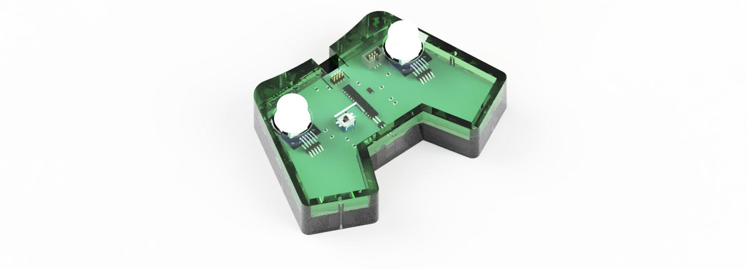
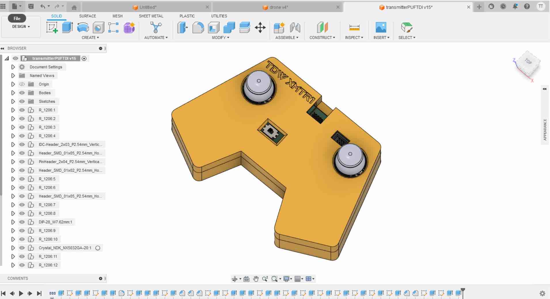
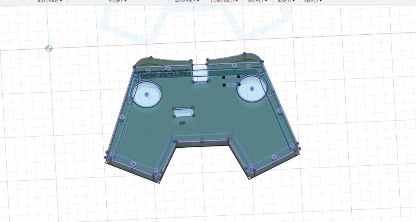
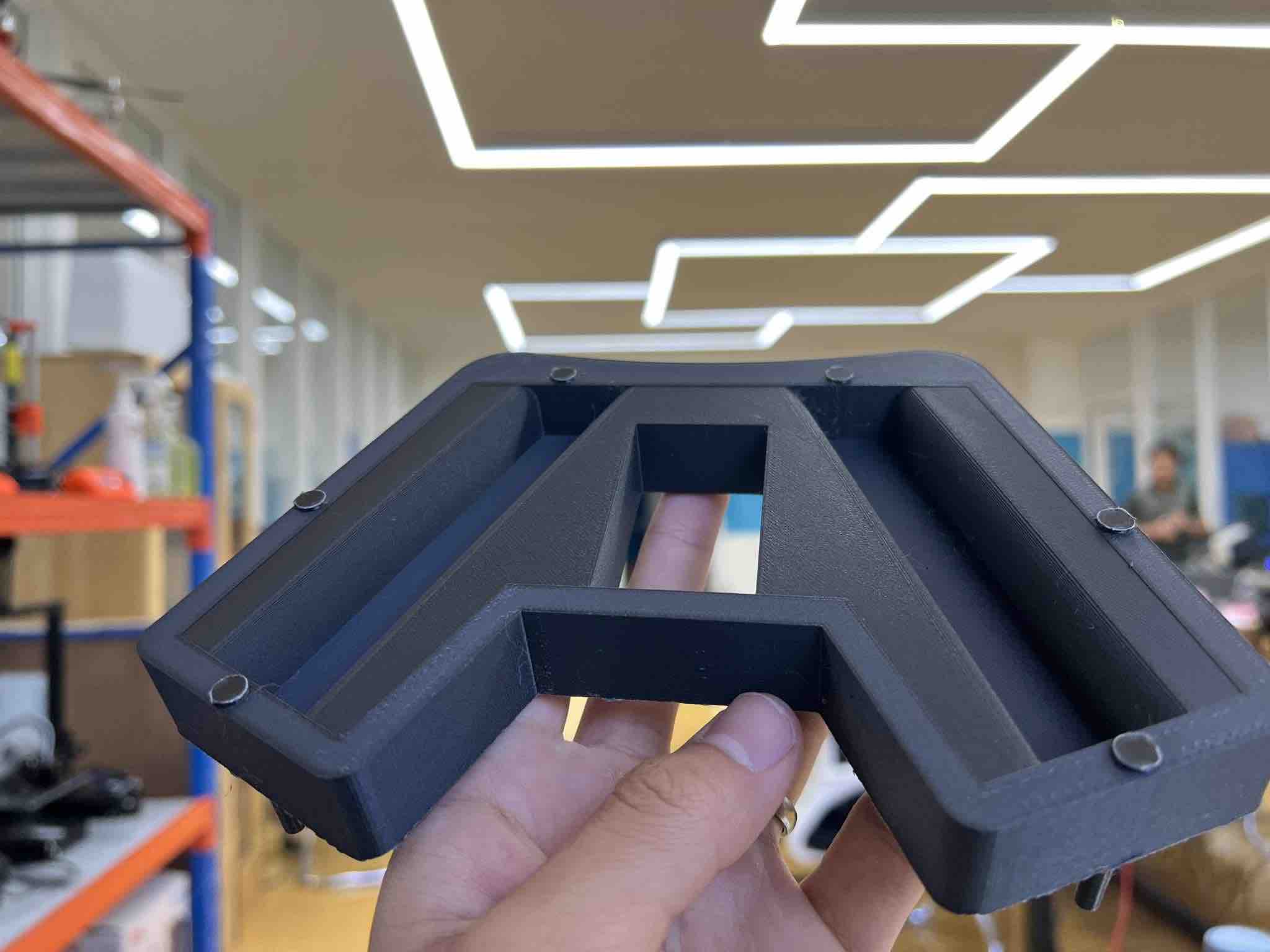
The major chunk of 3D printing in my project is the case for my transmitter. I began designing in Fusion360.
First, I exported my PCB as a step file from KICAD and then opened that up in Fusion360. This was done to give me a more detailed idea about the exact sizing of my transmitter. Then I also inserted the stls of the joystick that I found on grabCAD again for the same reason.
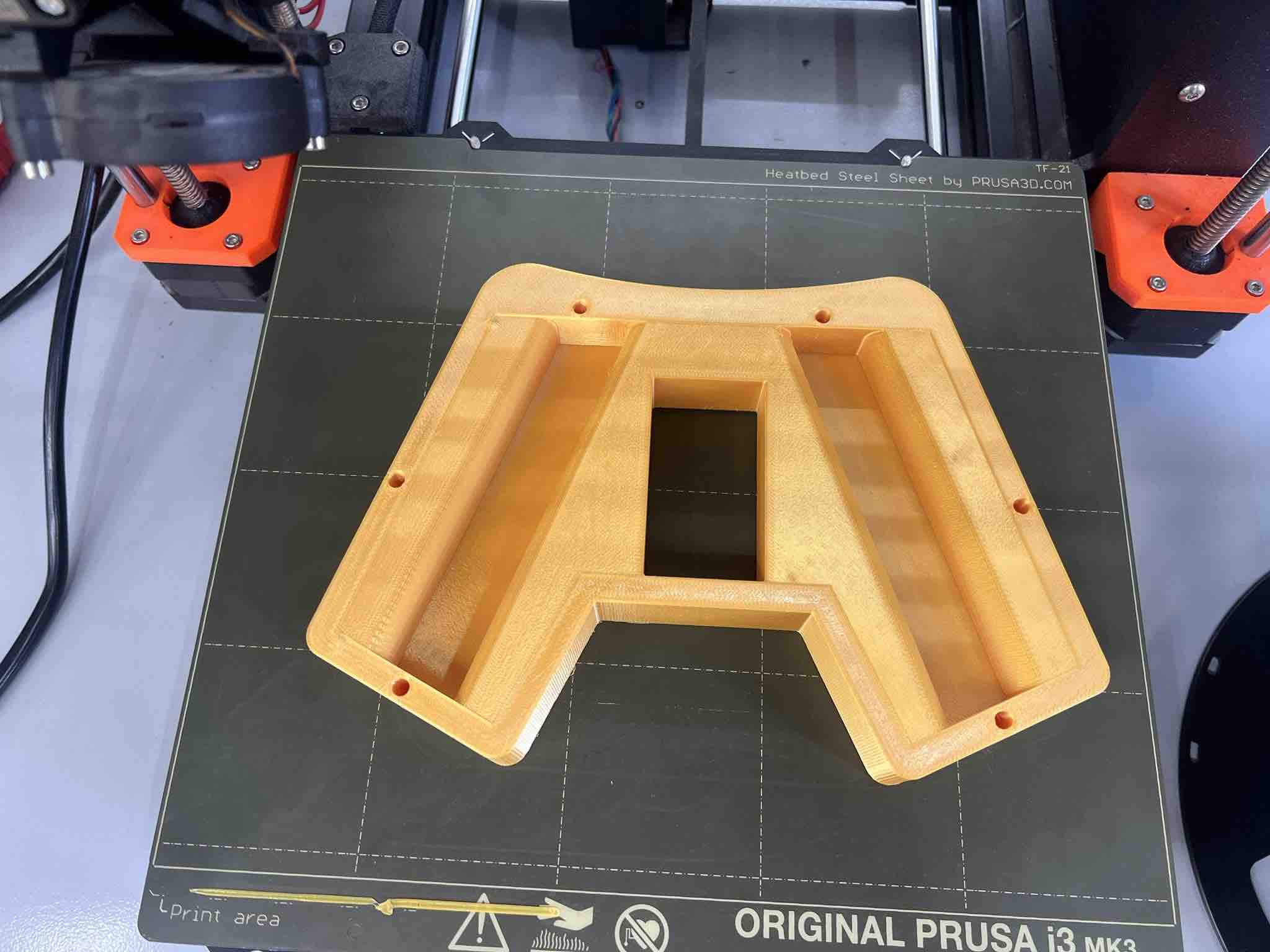
The bottom:
The Top:
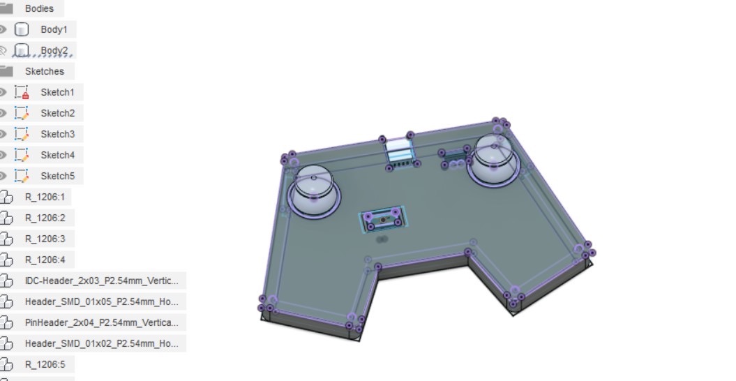
I wanted to split my joystick in two halves, the top and bottom, and it will be held together using screws.
Additive Manufacturing:
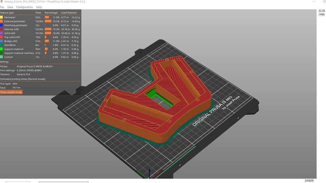
With all my components in I began designing around them, keeping in mind the tolerances based on the nozzle size of the 3D printer.
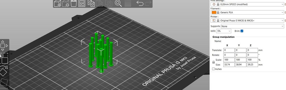
I used the lab’s Prusa mk3 i3+ and printed with PLA, and sliced my STL using the Prusa Slicer.
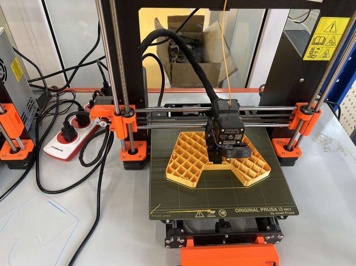
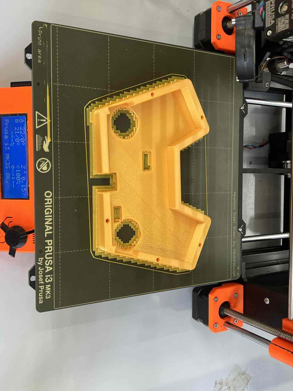
Here is how my first design turned out:
I am quite happy with this as it works perfectly barring some imperfections on the surface which I will sand. I will keep this as my final design while I work on other things but if I have the time, I will maybe tweak the design ever so slightly.
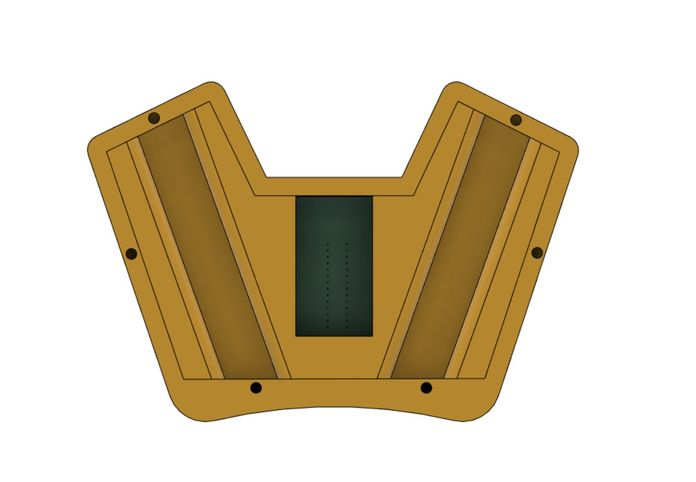
I realized I did not need the slit for the AVR since the programming will be down before inserting the board into the cover so I removed that.
### Spiral 2
for the next spiral of the transmitter case, I wanted to make the case more “user Friendly” and I wanted to add grooves/indents to the bottom side of the controller for better handling.
I went ahead and tweaked my pre-existing design to add said indents underneath the joystick case and then 3D printed it:
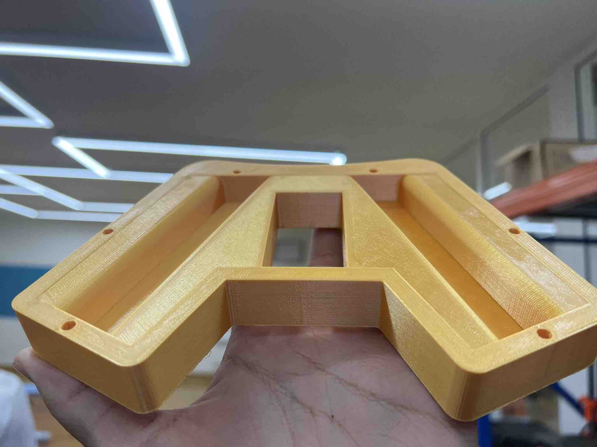
The design works perfectly as I wanted!
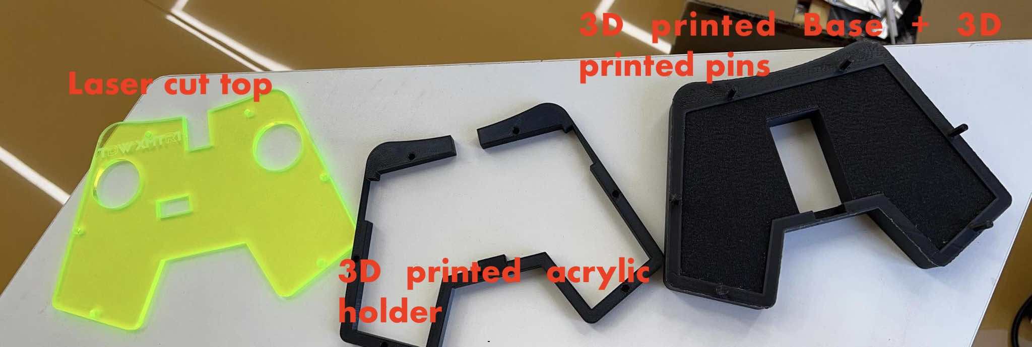
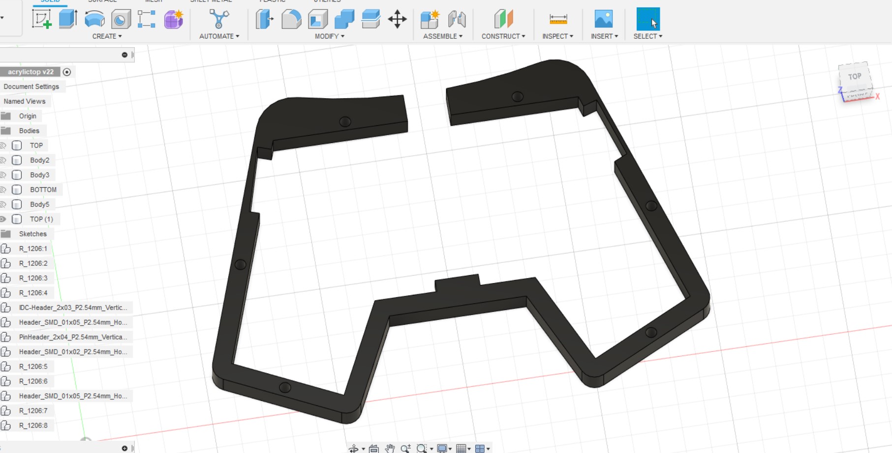
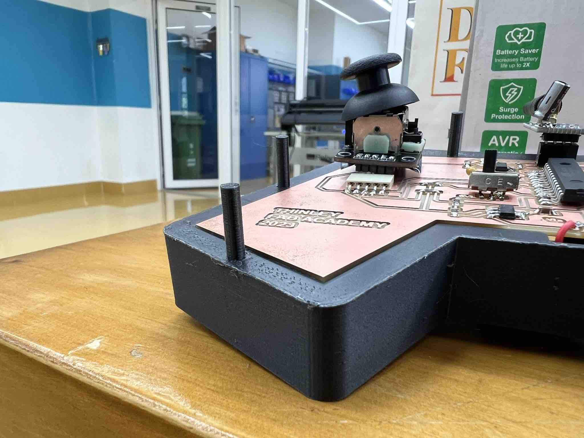
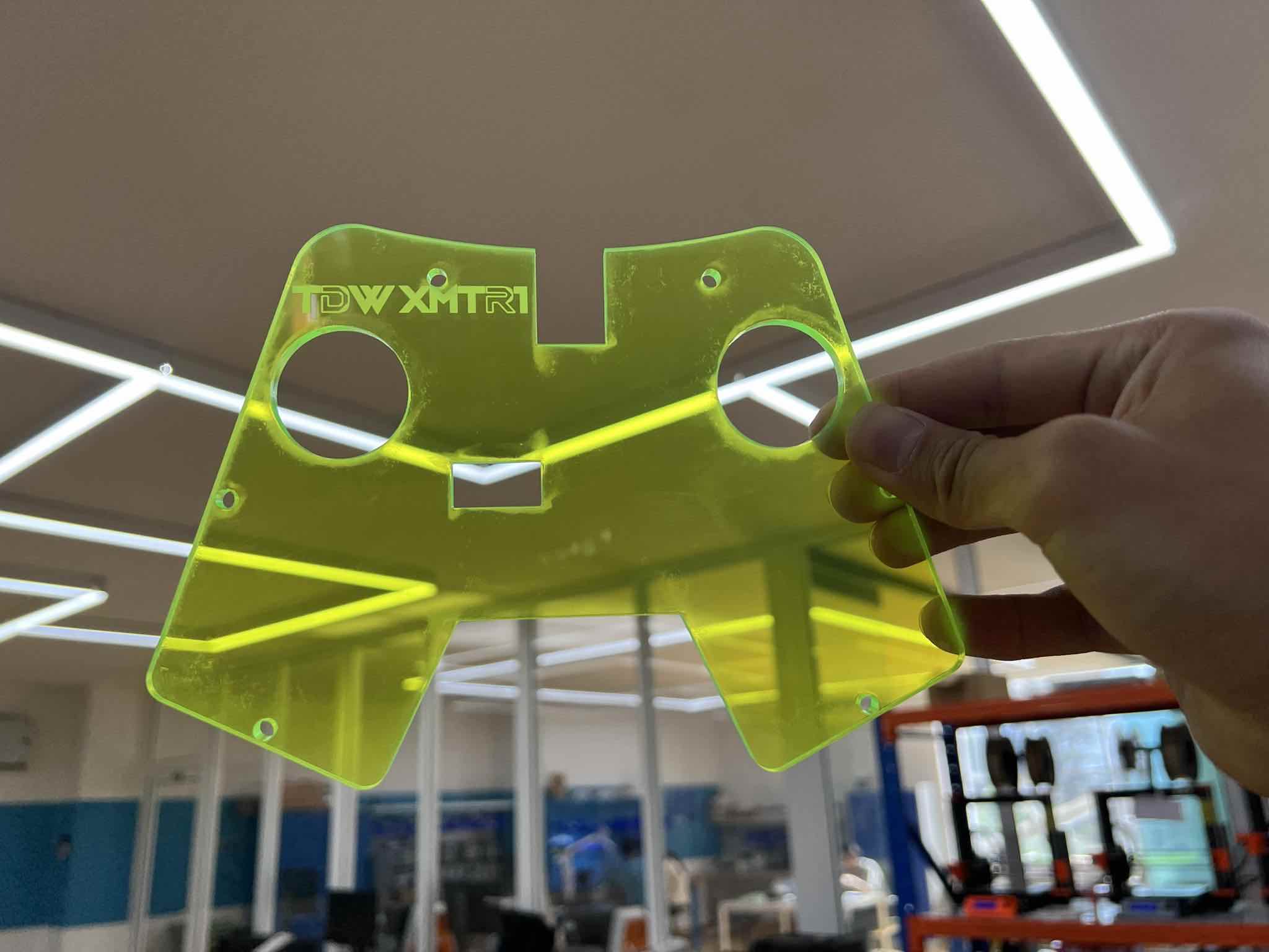
Next I got another Idea and thank you to Rico for the suggestion. The Idea was that I would use the 3D printed base to hold the joystick, but I would use acrylic on the top so that my custom PCB is see through!
I wanted to use Neon Green Clear Acrylic and that process can be found in the subtractive manufacturing section underneath.
For the acrylic, I just created a new sketch and projected the shape of the joystick onto the sketch and exported the dxf into inkscape to send to the Trotec speedy 100.
To hold the acrylic on the top, I also designed the acrylic holder in Fusion and 3D printed it.
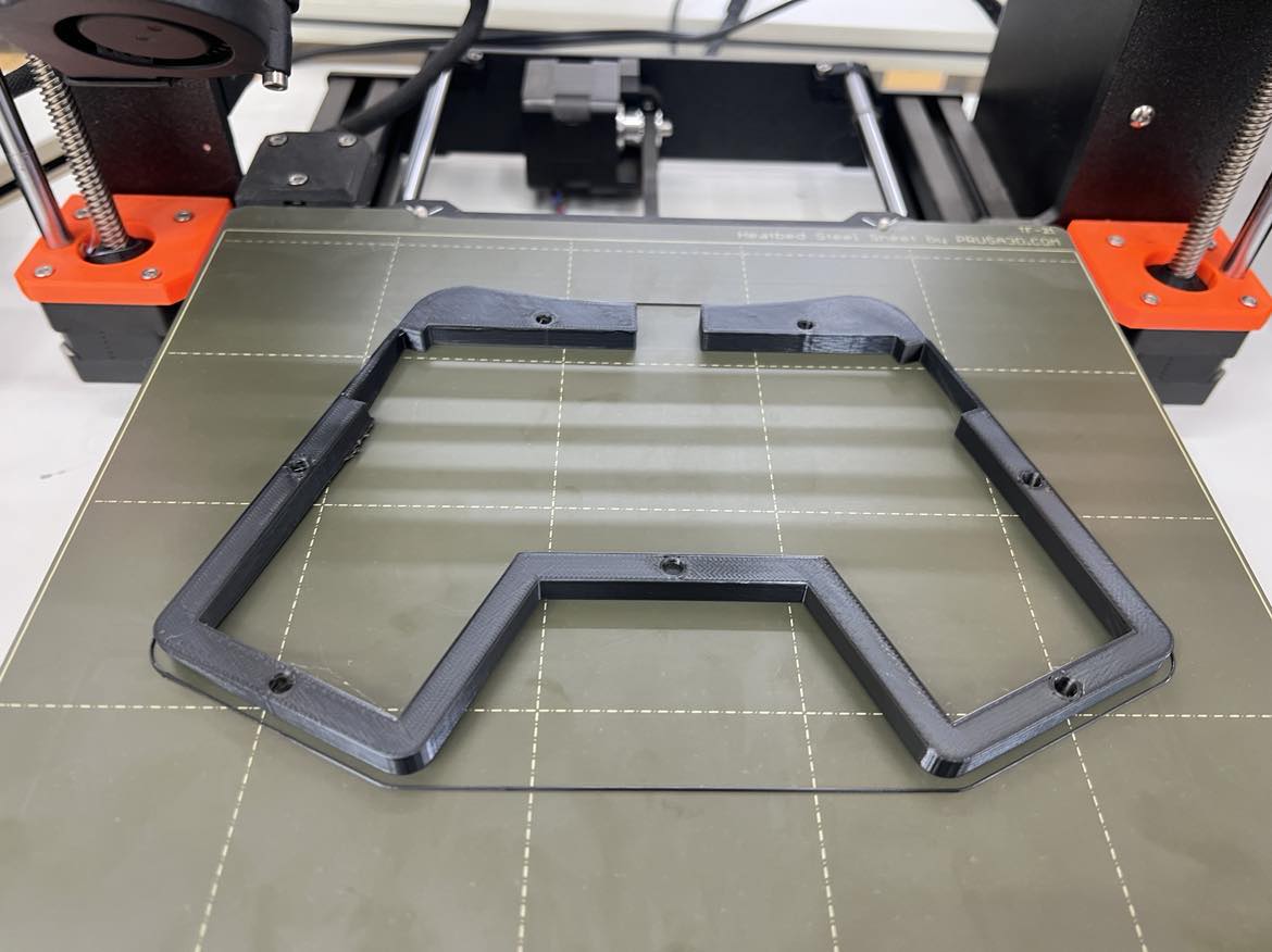
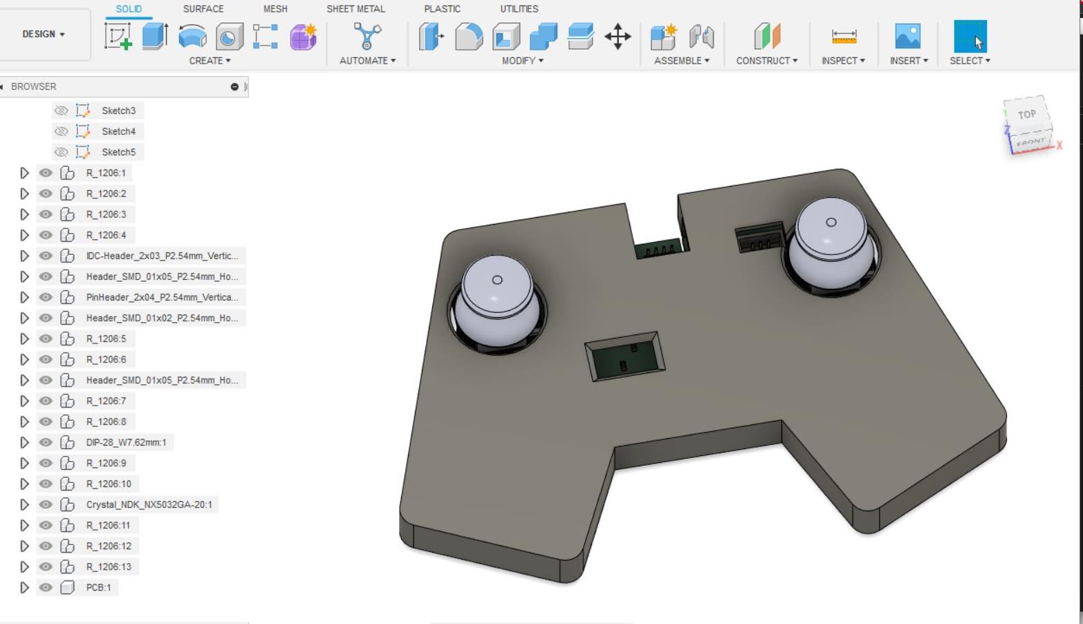
Since I was going to use green acrylic, I wanted to make all the 3D printed parts black so that it would stand out more so I went ahead and reprinted the base in Black (with the pin):
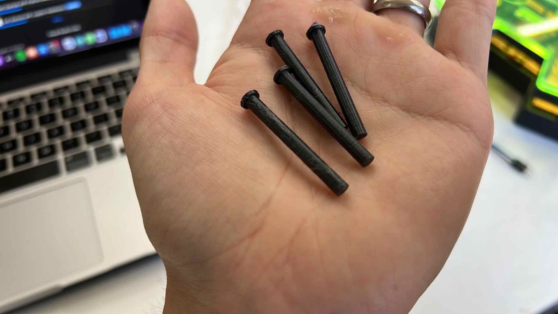
Pins:
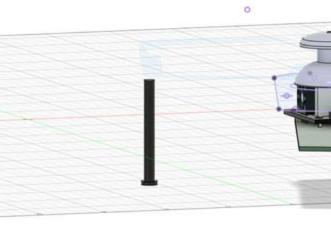
To hold the entire case together, I wanted to forgo using screws and wanted it to be completely 3D printed so I designed and printed the”3D printed Pins” to hold it all together.
Heres the Base + the transmitter Board + the Pins:
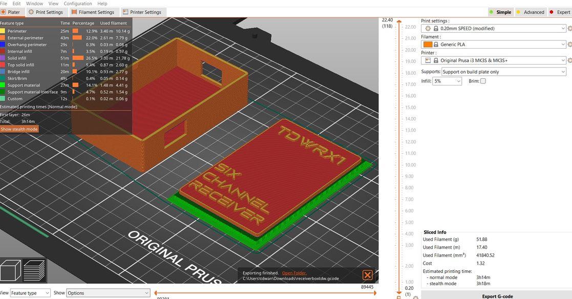
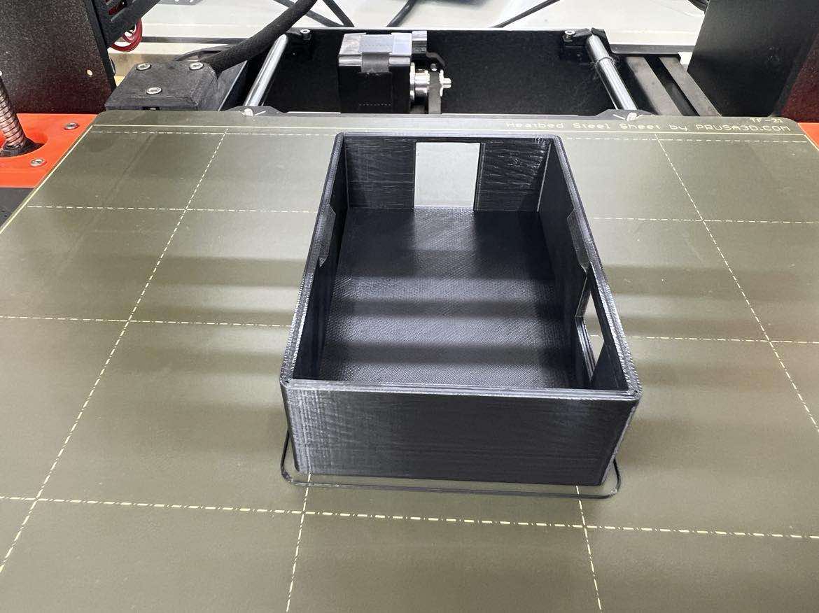
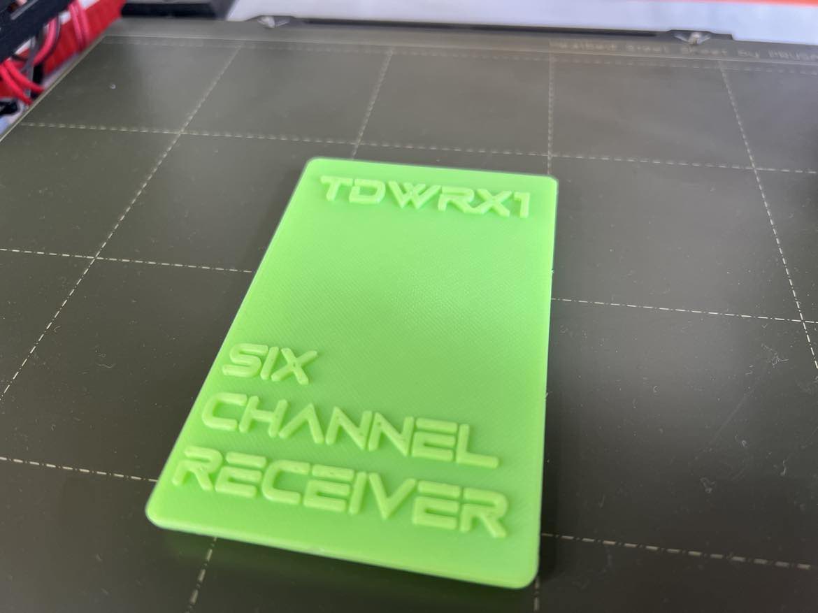
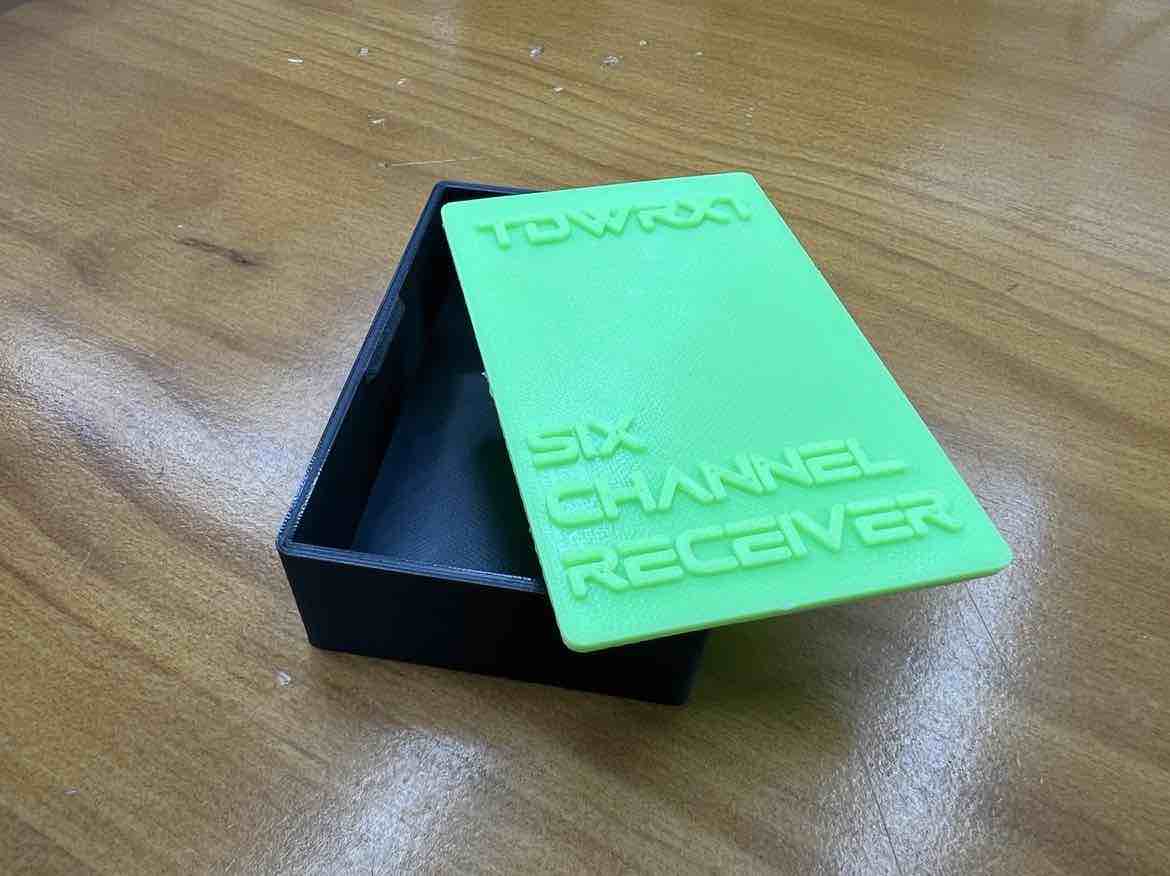
Spiral 3
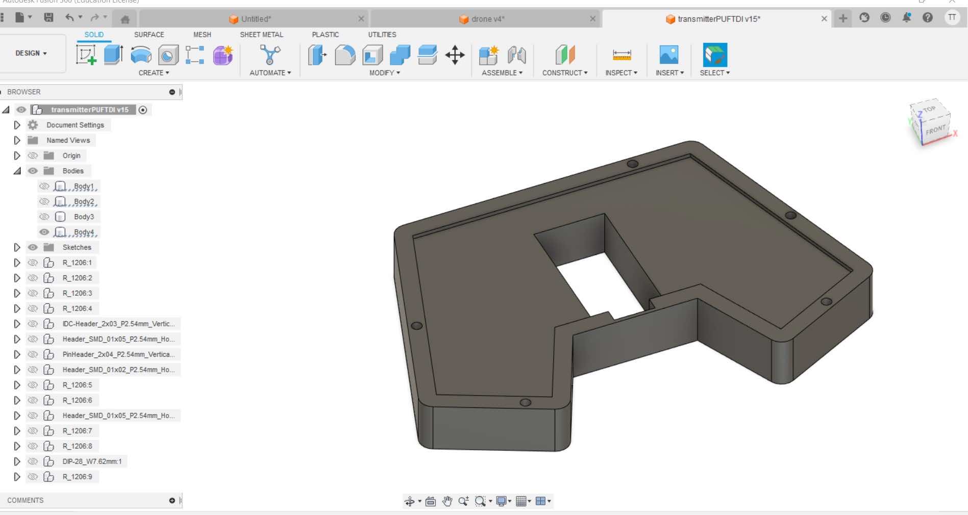
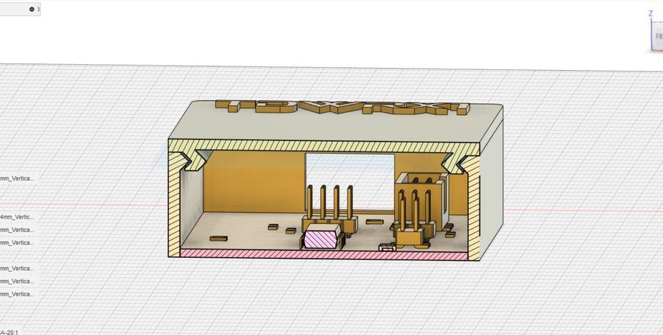
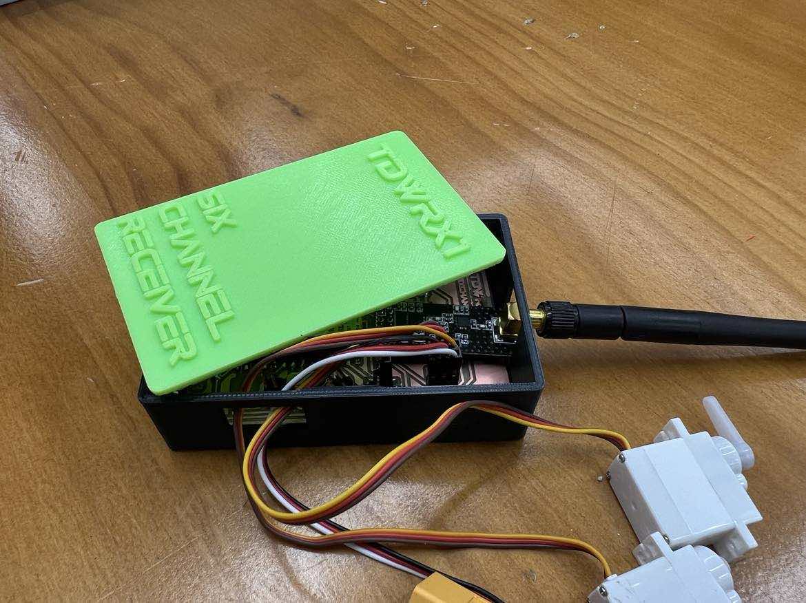
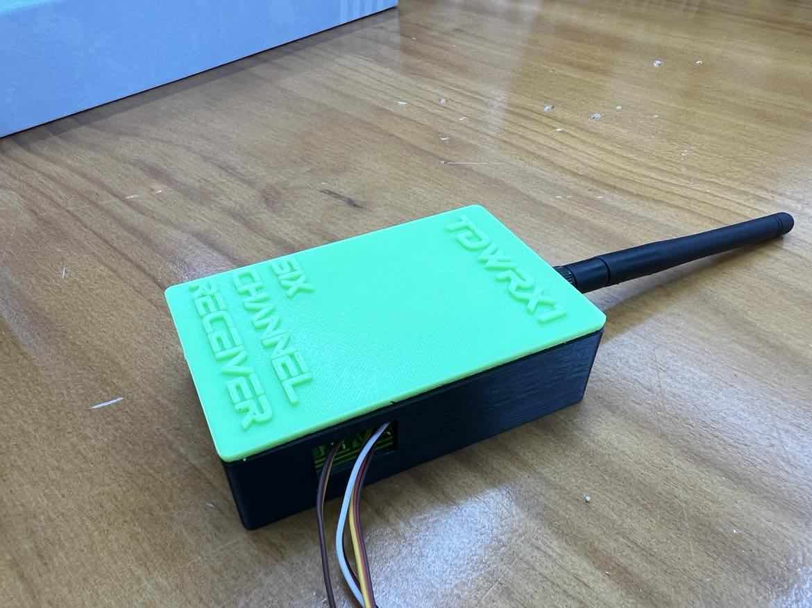
Next I wanted to make a housing case for my Receiver Board. I used Fusion360 to design it. First, I imported my kicad step file to get a better understanding of the dimensions of the board.
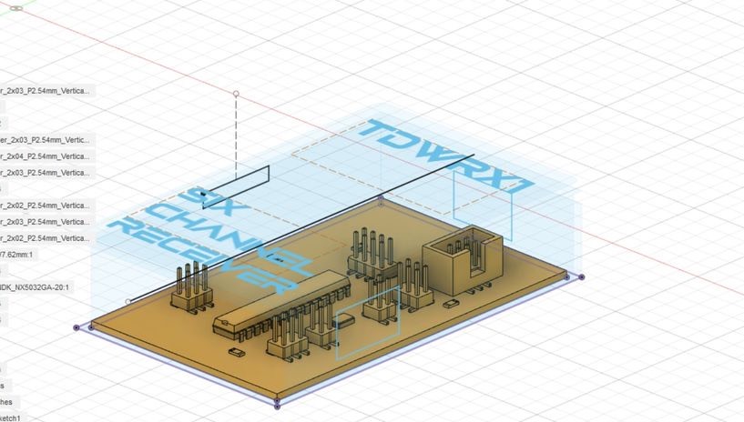
I wanted it to make it have a snapfit locking mechanism to eliminate the use of screws.
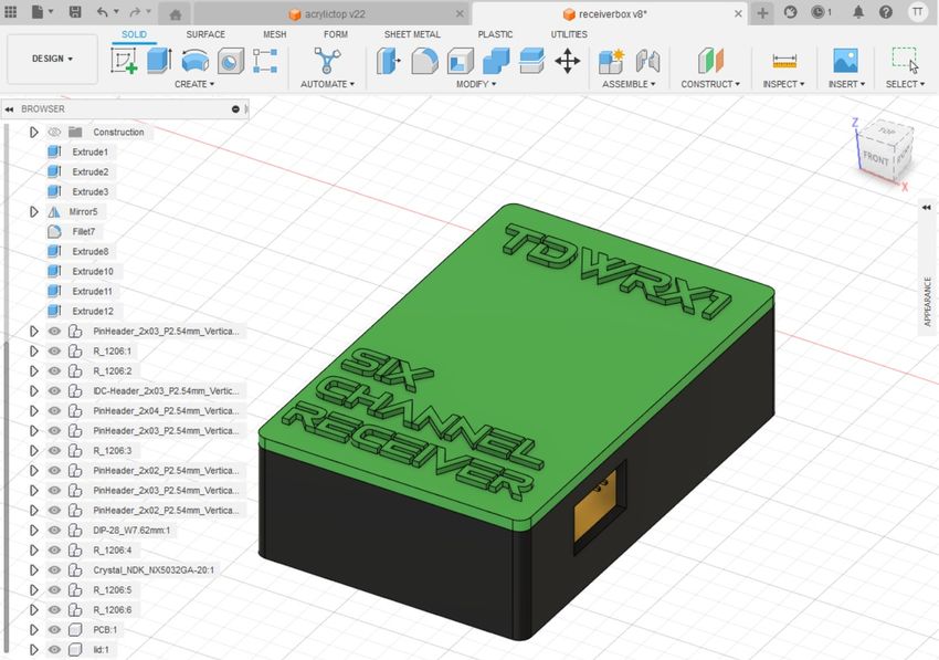
Then I used the Prusa slicer to slice the STL file.
The Drone:
Initial planning and design
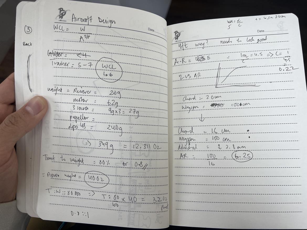
My rough notes on how I ended up with an Aspect Ratio of 6.25.
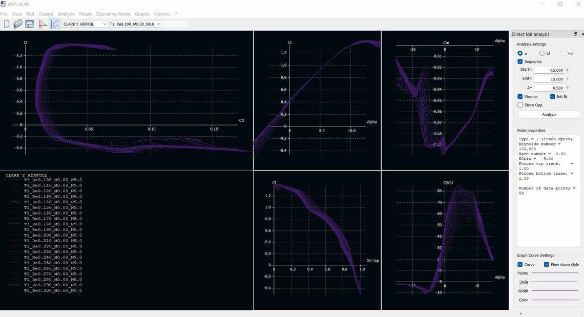
Aerodynamic analysis (XFLR5)
I knew I wanted to work with the ClarkY Airfoil because it is a flat bottomed airfoil. It is not commonly used any more, but since I will be working with cardboard to make the drone, having a flat bottomed wing makes a lot of sense.
I went ahead with the direct Foil analysis in XLFR5:
Initially selected:
Aspect Ratio: 5
Chord length: 20
Wing span: 100cm
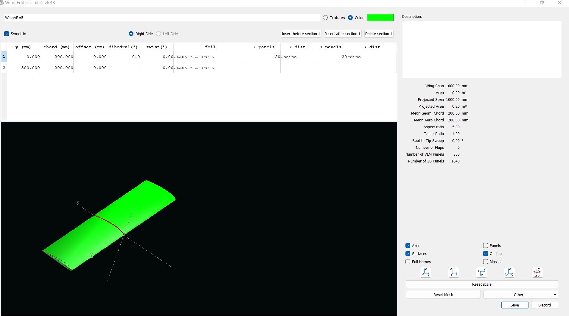
I tweaked my design and calculations a little and decided to go for more Aspect ratio, reducing the chord length to 16cm
Fusion360
The wing:
ClarkY airfoil
Chord Length: 16cm
Total wingspan: 100cm
Aspect Ratio: 6.25
Dihedral of 2.8 mm
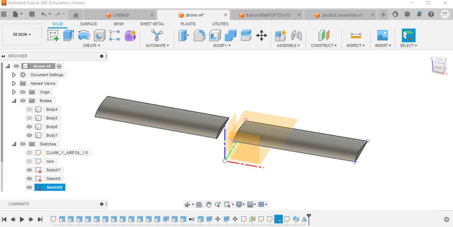
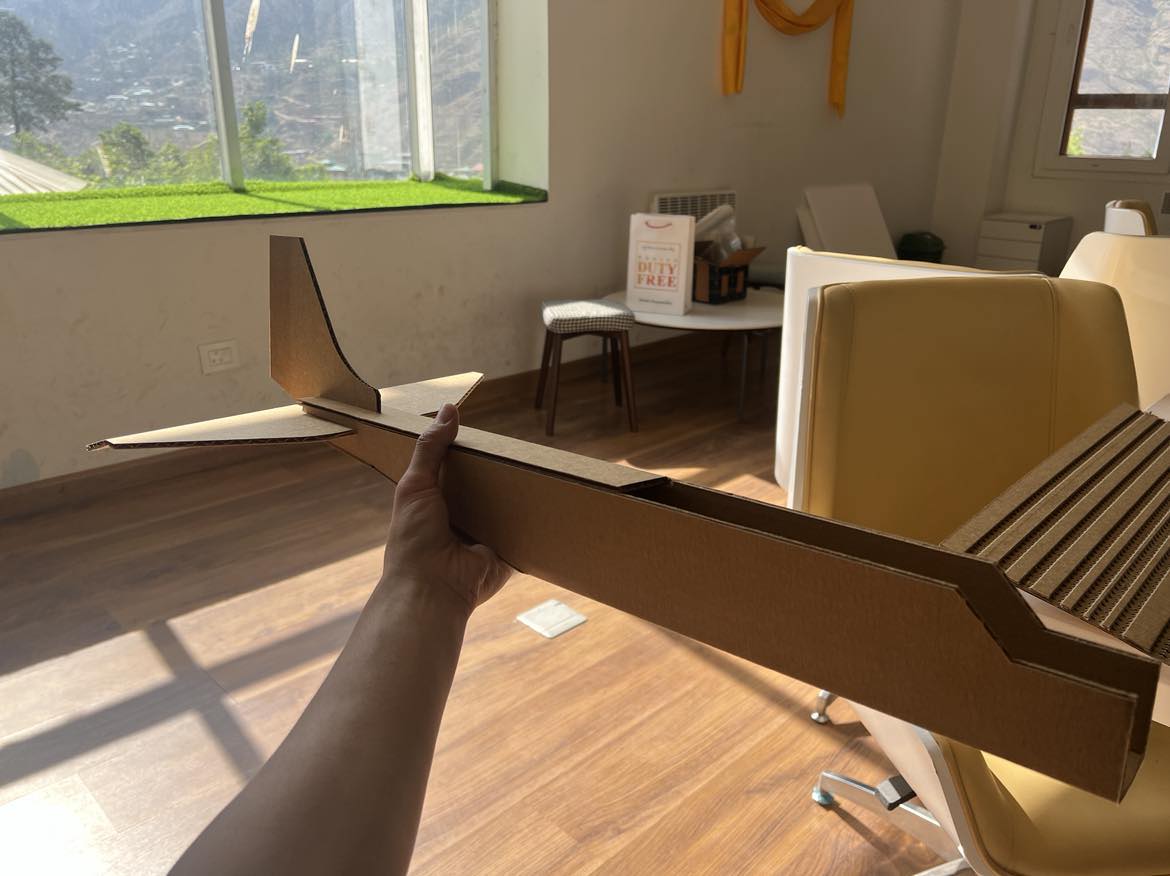
The Final Drone:
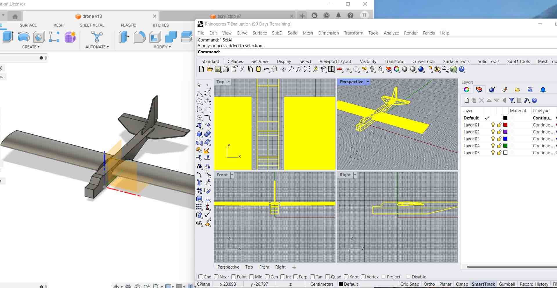
Rhino3D
I imported the Drone’s Step File from fusion360 into Rhino3D
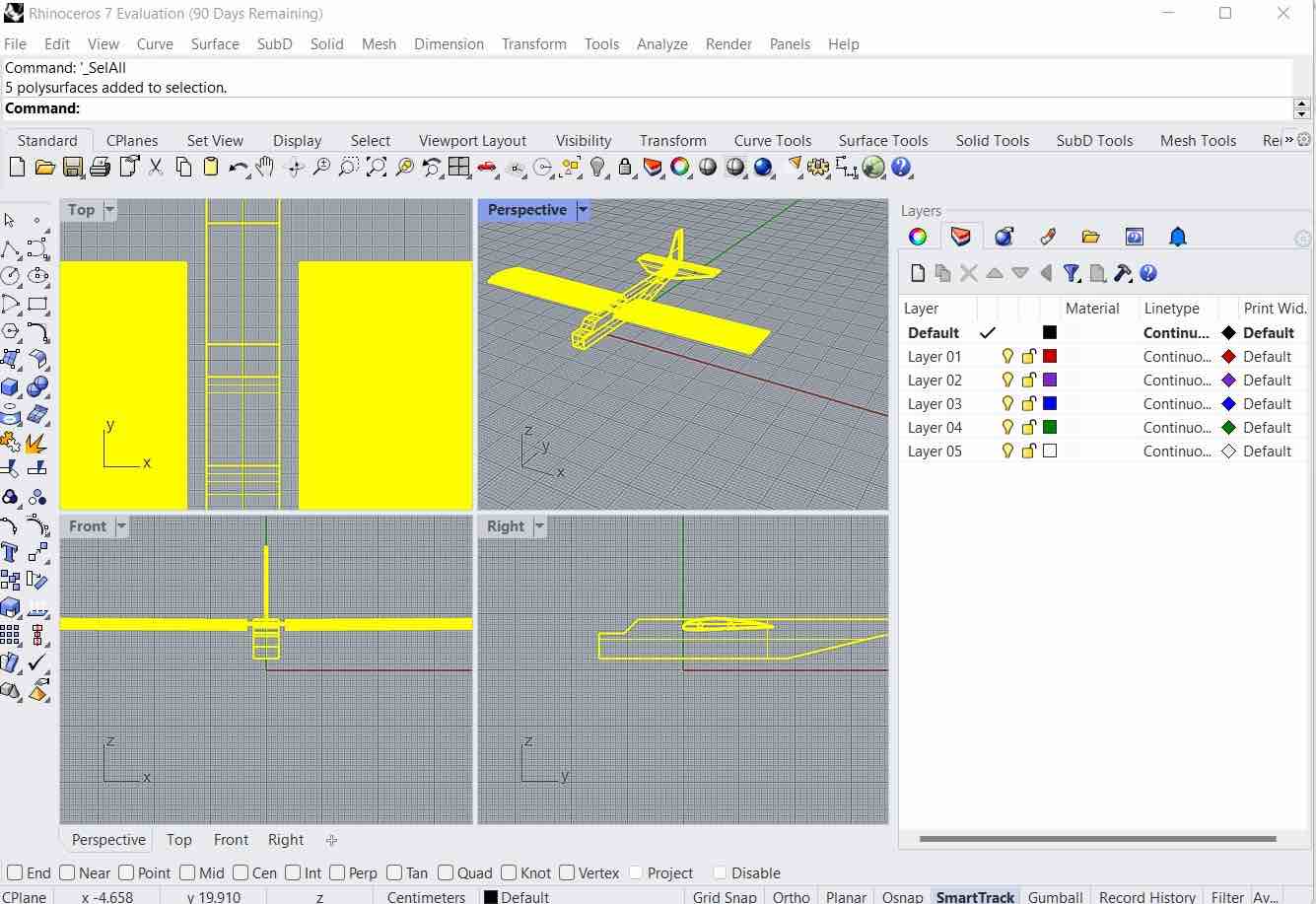
Then I exploded and Unrolled the parts in Rhino360.
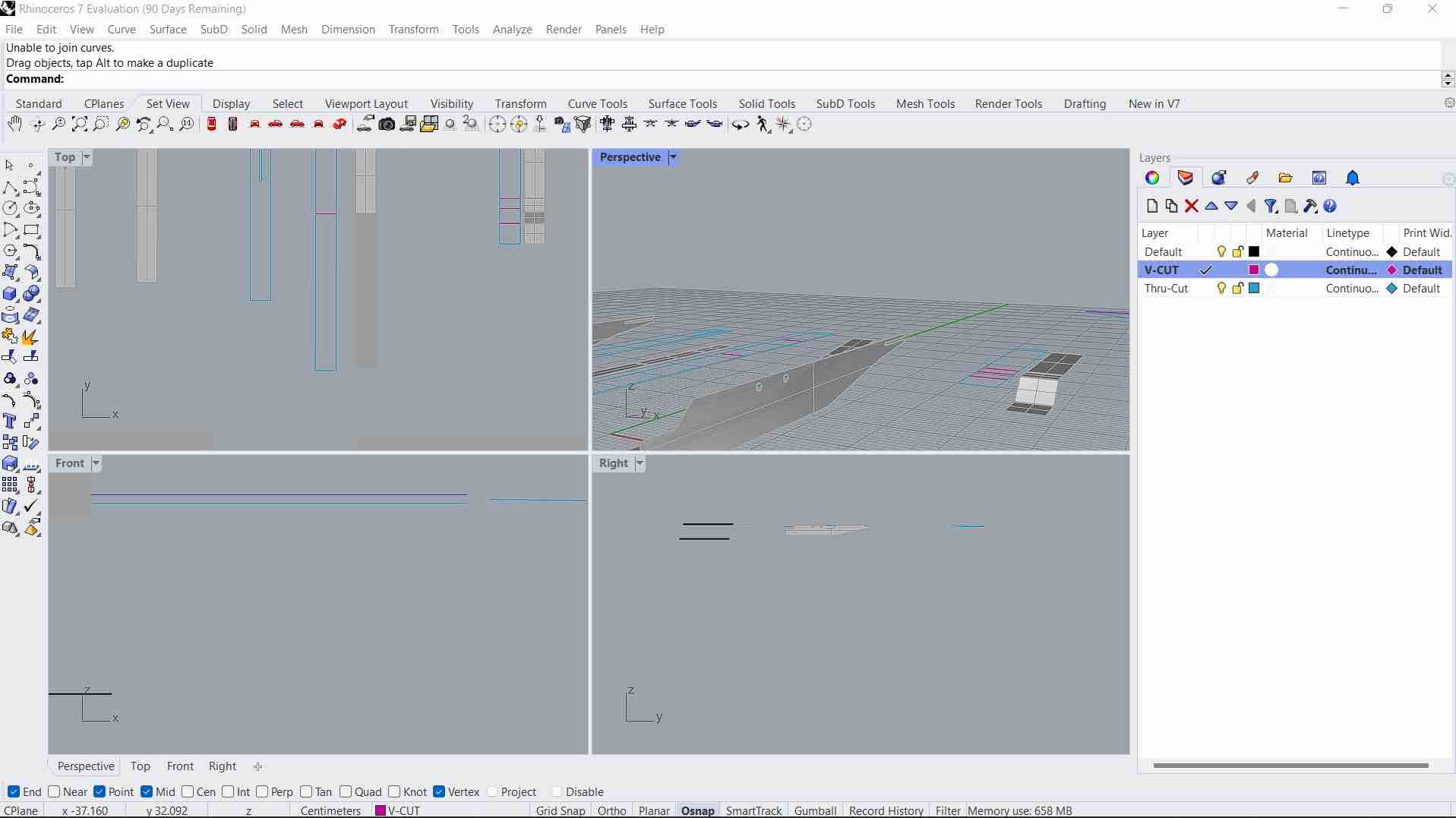
I created different color coded layers to show v-cut or thru-cut.
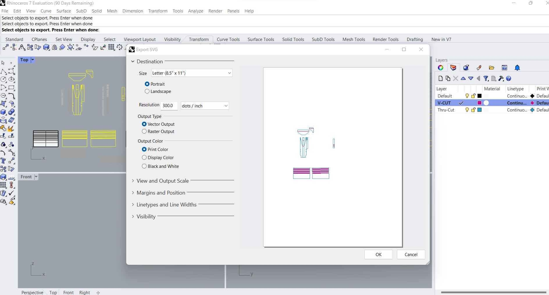
Then I exported the 2D structures as a SVG for the Zund. The SVGs will be converted into DXFs in Inkscape so that it is readable by the Zund.
Subtractive Manufacturing
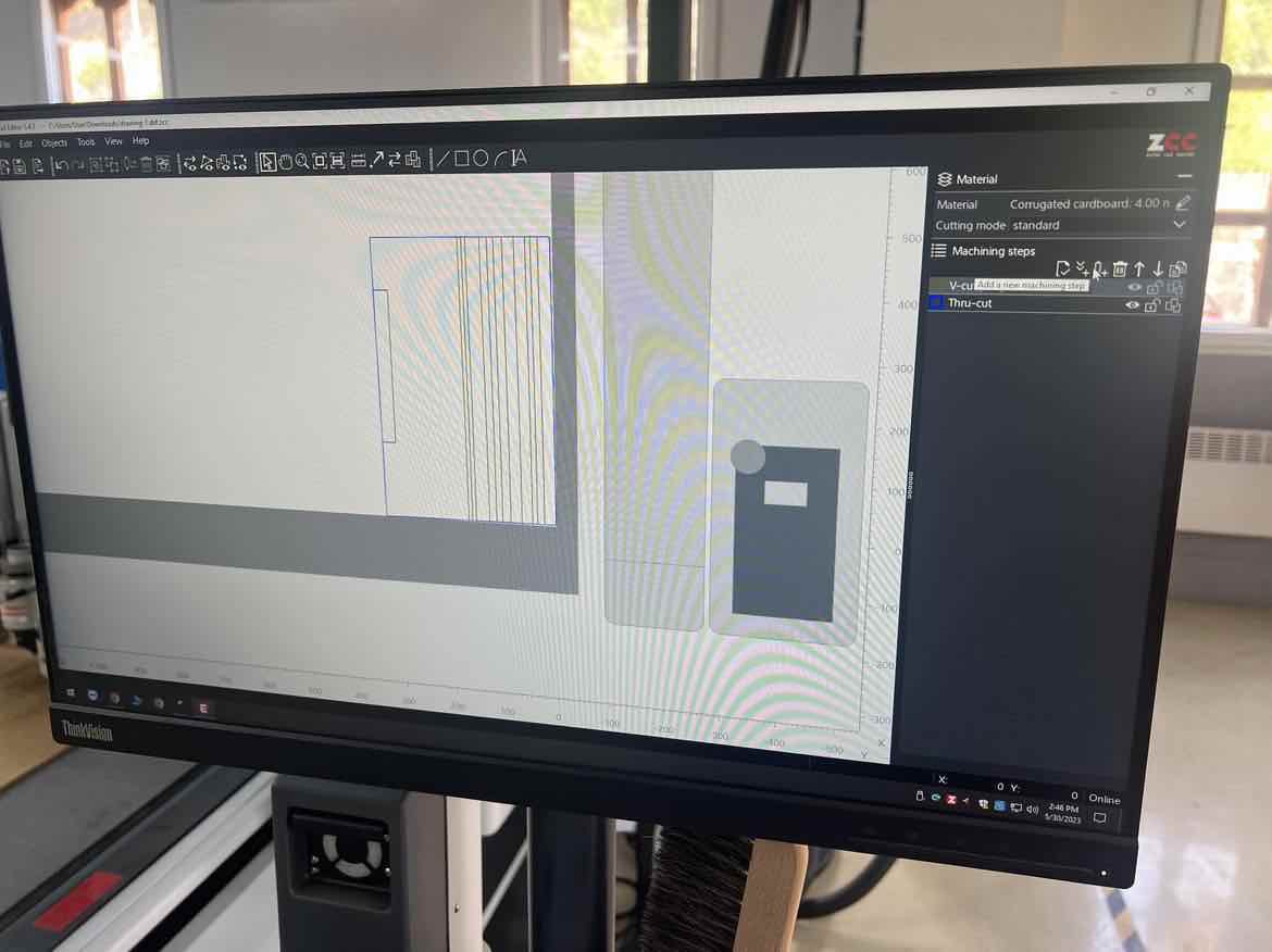
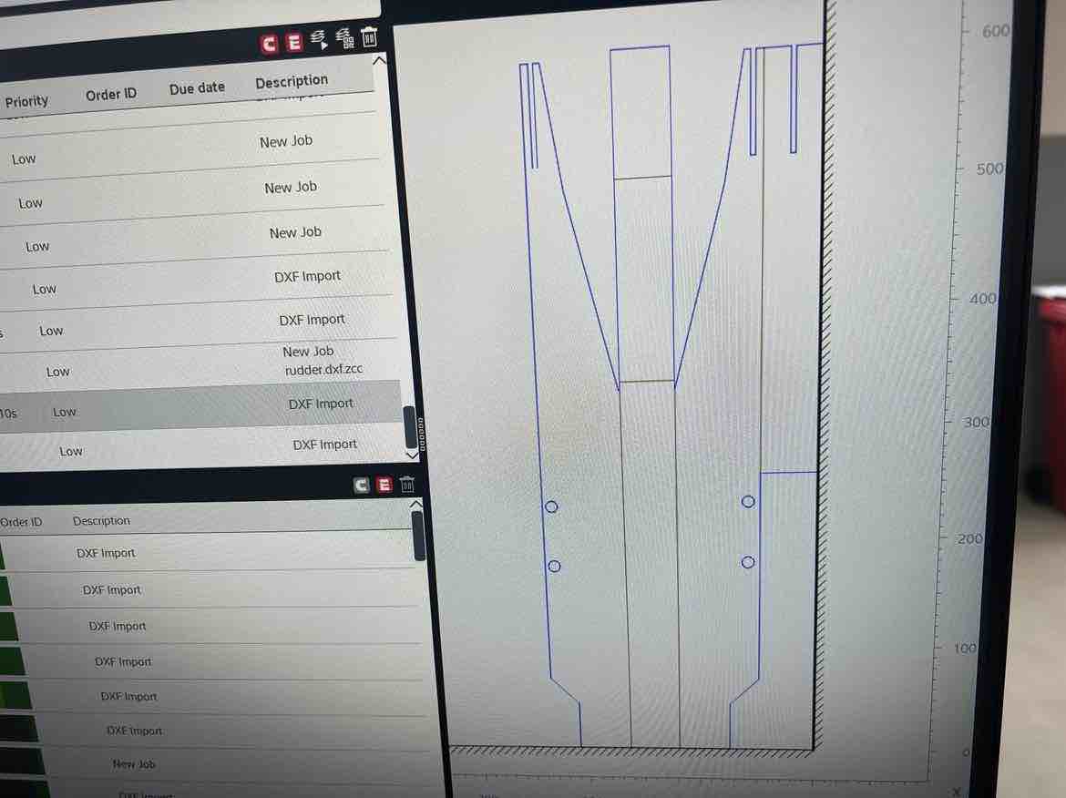
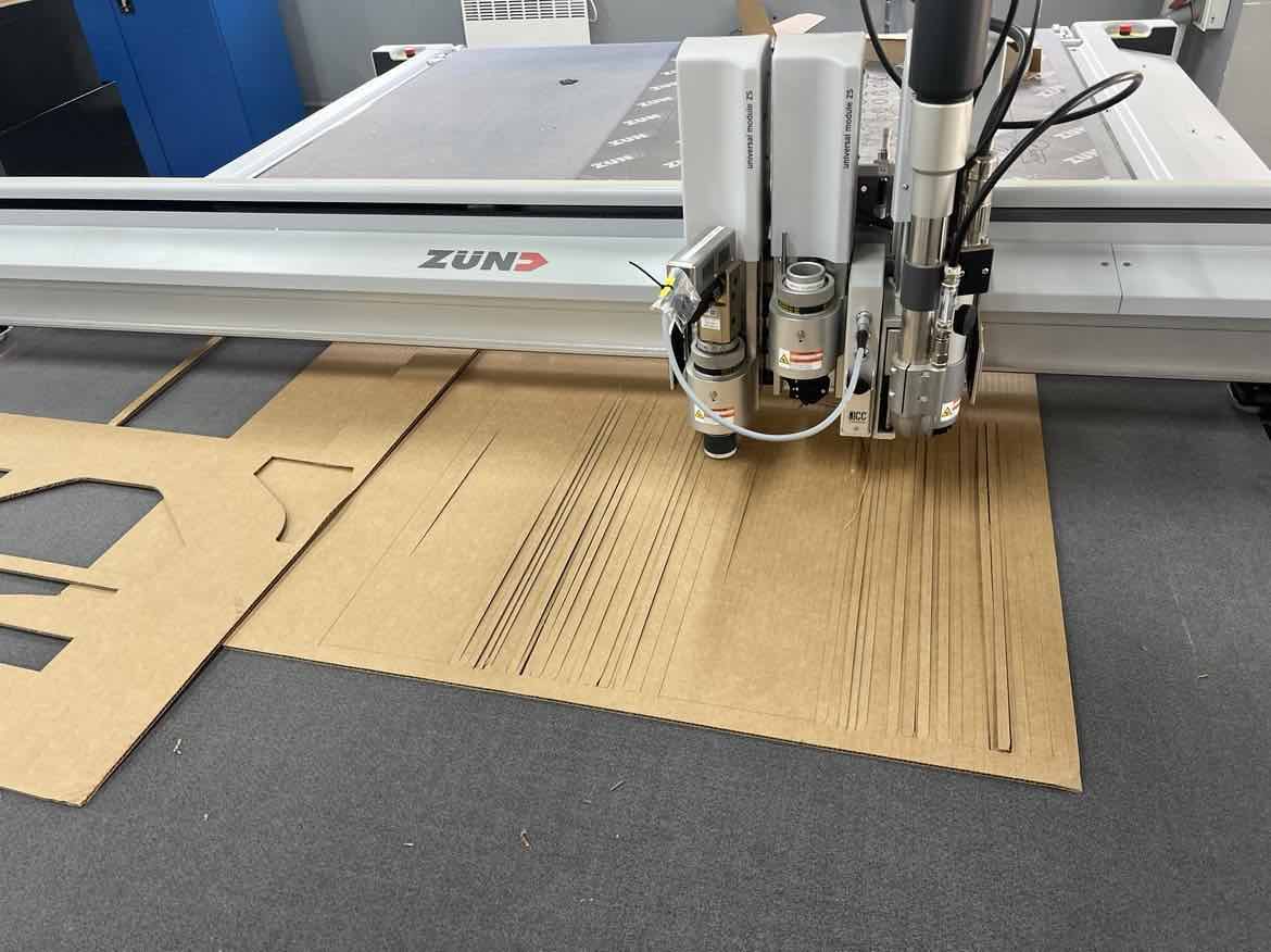
ZUND
Using the Zund I cut all my parts out of cardboard. I imported the dxf’s and then assigned the different job methods as required.
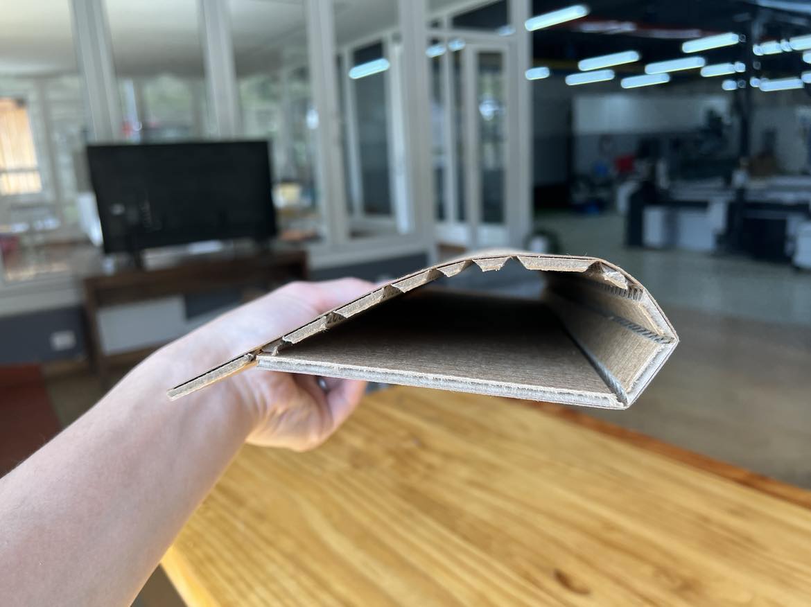
Beautiful folded Clark-Y shape:
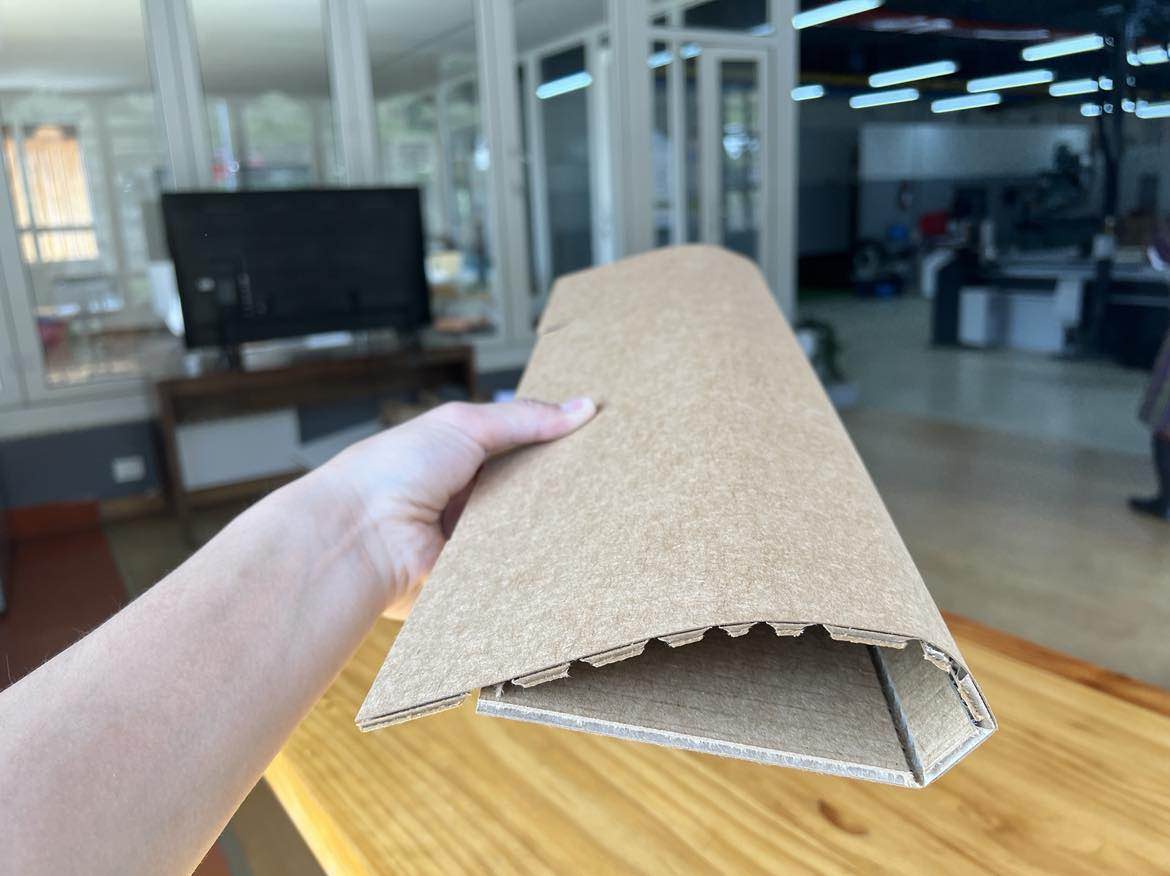
Fuselage:
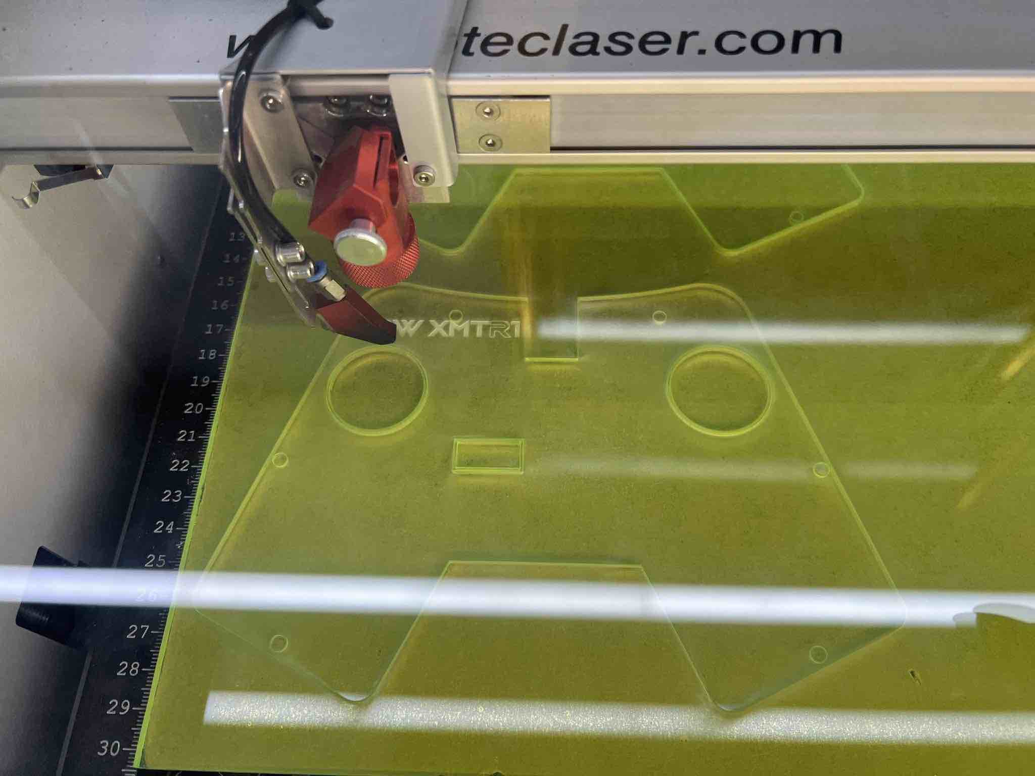
TROTEC Speedy 100
As I explained above, I wanted to make the top out of acrylic so I used the trotec speedy 100 to laser cut the acrylic.
I created a new sketch in fusion, and then projected the top of the joystick into the new sketch. Then I exported that sketch as a DXF and imported it into Inkscape.
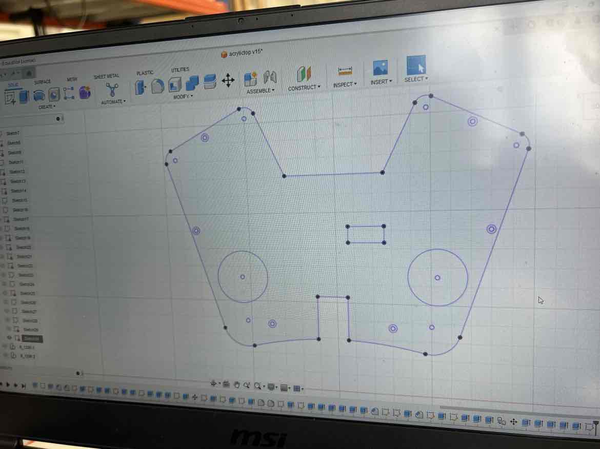
In inkscape, I set the lines I wanted to cut to Red (0.01mm) and the parts I wanted to engrave to black.
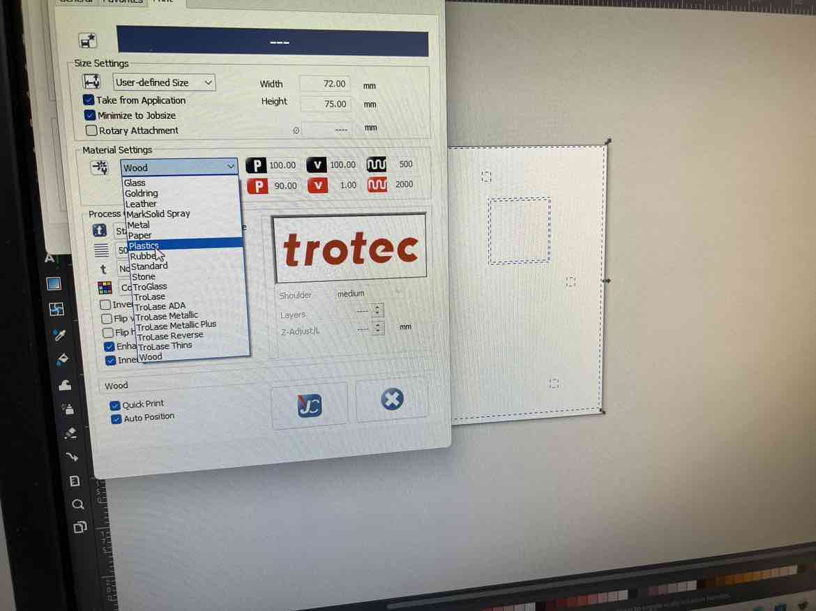
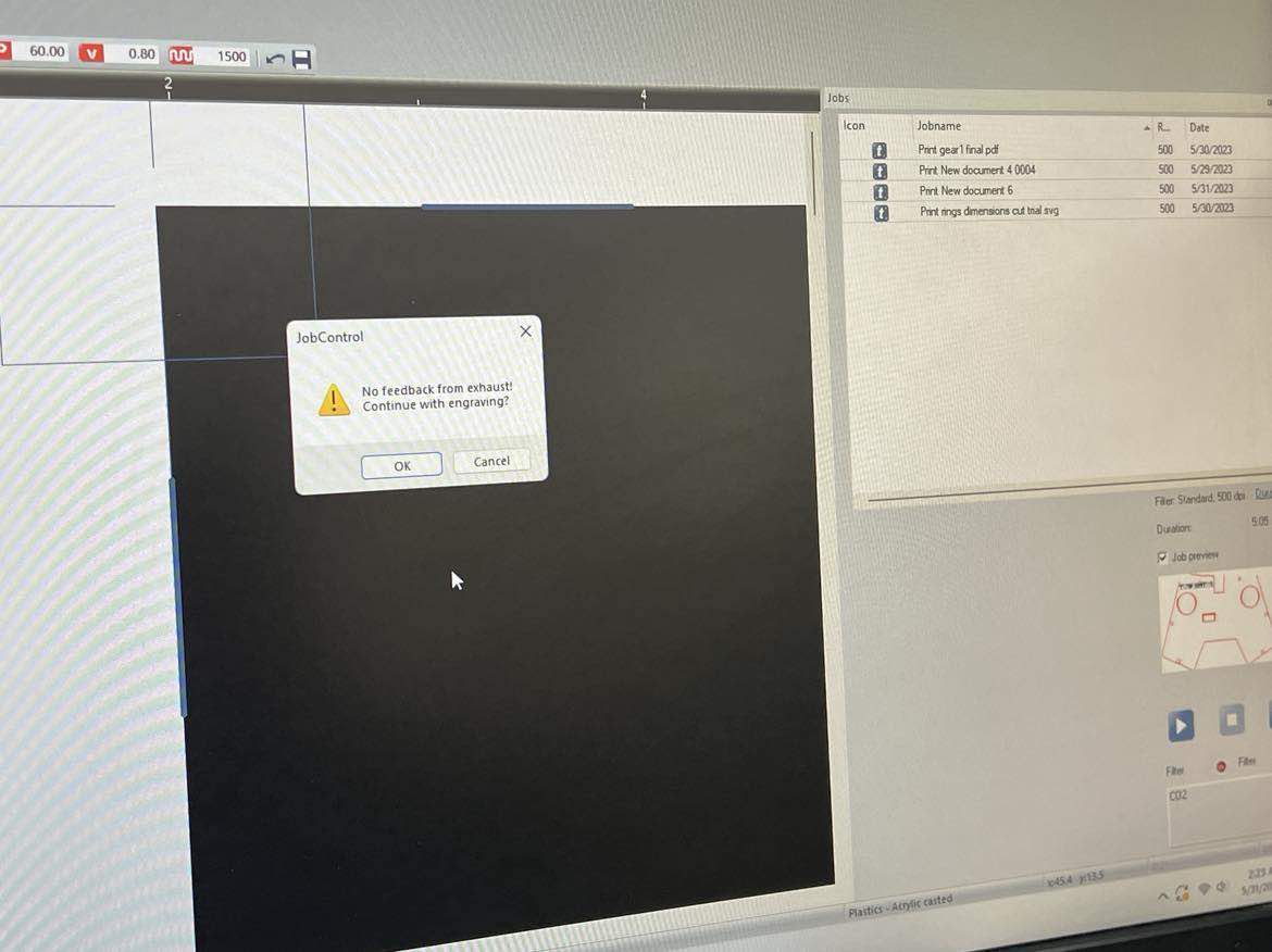
Then I hit, print to send it to the Trotec Job center where you define the power, velocity and origin of your job.
I started the machine, set the z axis and also my x and y positions.
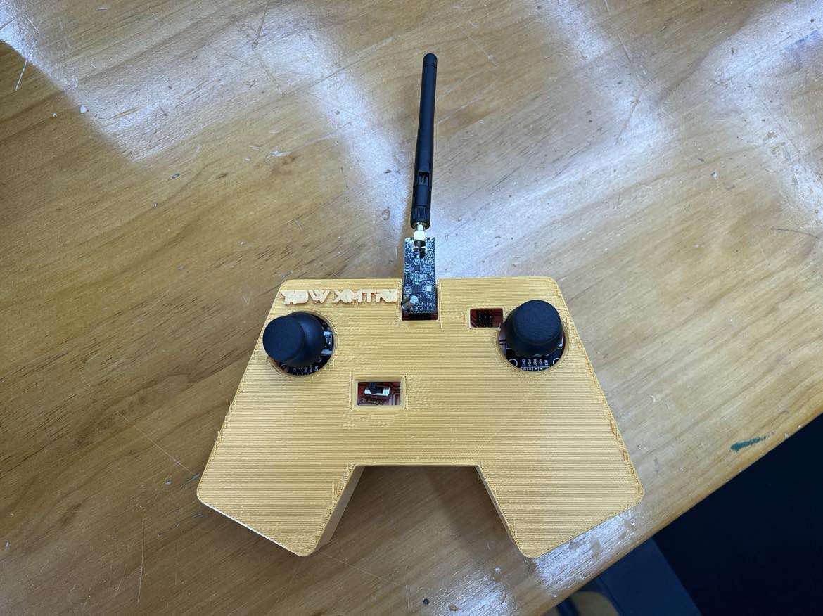
Final Transmitter Assembly:
Subtractive + Additive Manufacturing