Week 3. Computer-controlled Cutting
This week we begin the more hands-on part of the lab where we use the machines (especially the public favourite laser cutting machine).
The Laser Cutter
Our lab has two laser cutters, the Trotec Speedy 400 and the Speedy 100. Since the Speedy 400 is bigger, I find myself using it more so I decided to do the assignment for the week on the Trotec400.
The Trotec 400 Workflow:
-
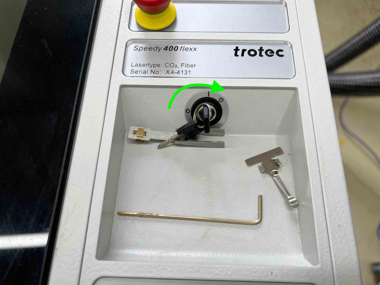
First turn on the machines power source and then turn the knob to the right (like starting a car).
-
Ensure the lid is closed. During initialization. Wait till the laser homes and wait for a beep. You can open the lid after a beep is heard once the machine is done homing and starting up.
-
Open the Lid and place the job piece in the workspace. Good habit would be to place it at the origin 0,0 which is at the top left of the workspace.
-
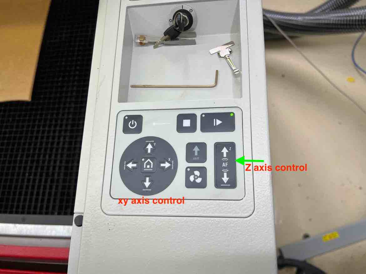
Move the laser head by using the arrows on the machines’ interface. The z axis can also be raised or lowered with the the up/down arrow keys that has the z symbol on it, in the same area.
-
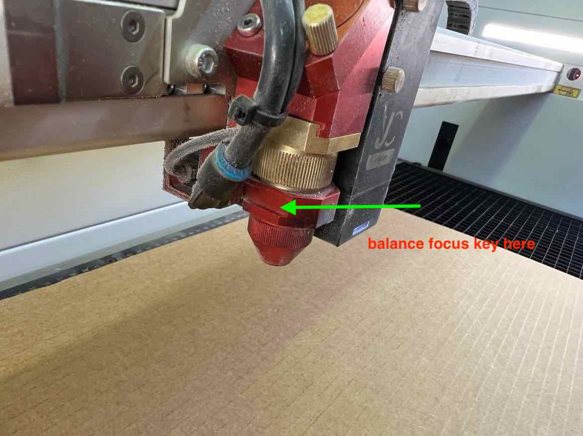
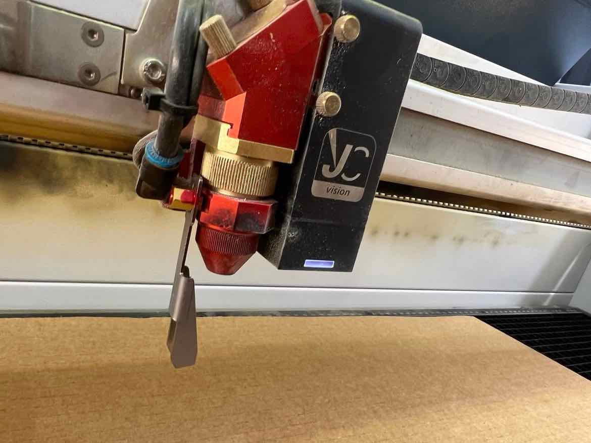
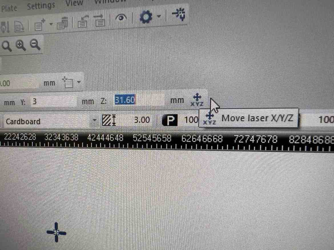
The next important part is setting up the z axis for proper focusing of the laser. For this, take the focusing key and place the square side of it on the ledge on the laser head. Then, raise the z axis until the key barely falls off the laser head.
-
After setting the z axis, homing the laser head and placing the work piece on the workspace, begin working on the design. Ensure to turn on the exhaust vents.
-
Inkscape was used for the design. By default a black fill will engrave and red lines will cut. Ensure to set the proper colors and ensure to set the stroke thickness to either
hairlineor something like0.001mm. Ensure to resize the page to fit the content Once you are happy with the design, go to file -> Print -> in the dropdown menu selectTrotec Engraver-> hit print.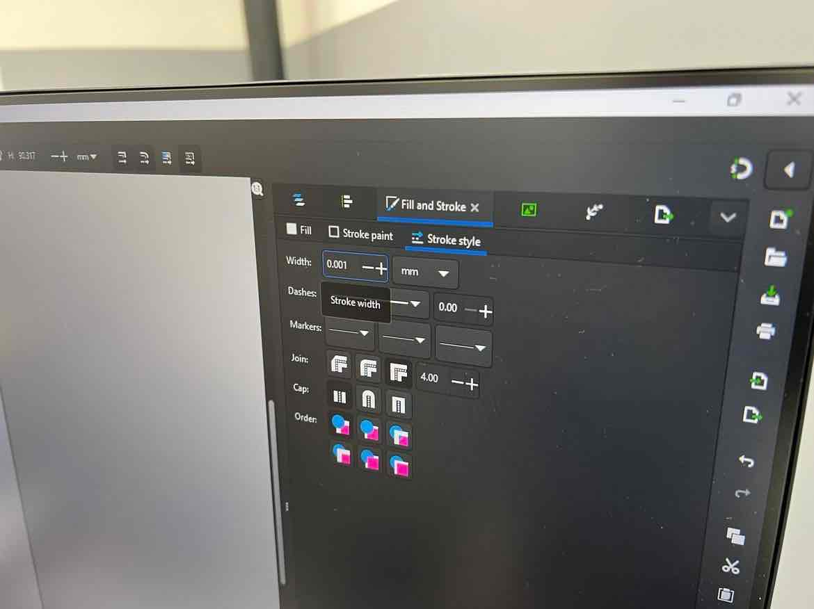
-
In the next menu that pops up, you can set the sizing, material type and can change settings of the process in less detail. In our case, paper-> cardboard was selected. Hit
JCto send the design to the job center which will open.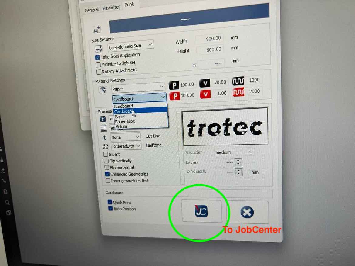
-
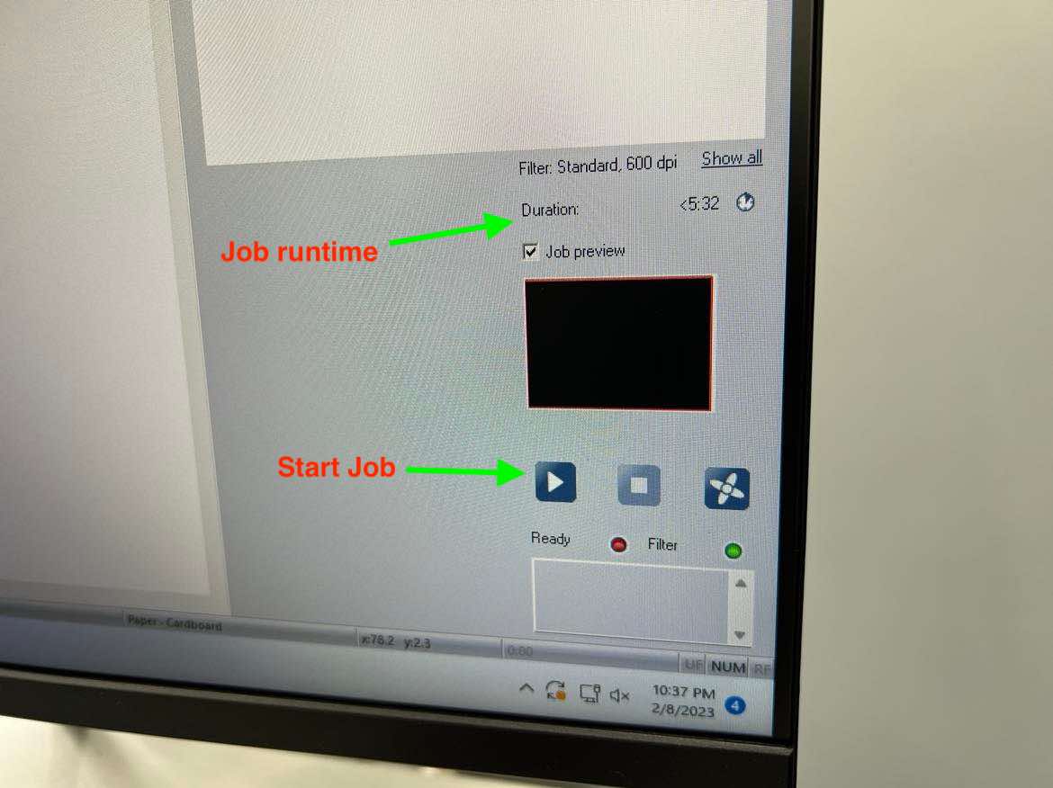
In the job center, you can move the laser head by using the coordinates if you want. Here you can adjust everything from the power, velocity, frequency (for engraving and cutting), material type, move your design, move the laser etc, to completely personalize your work.
-
Ensure to place the top left of your design in the center of the laser’s pointer. Hit the
playbutton to begin your job.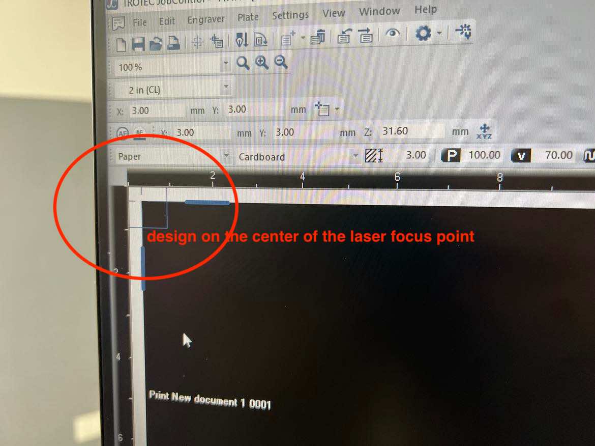
-
Ensure that you are always by the machine when the job is running, with a fire blanket and fire extinguisher nearby for safety.
-
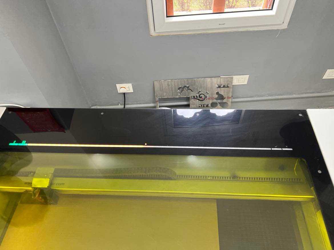
Once the job is done, keep the lid of the machine closed for a few minutes to ensure that any fumes, smells don’t escape. Theres a display bar on the machine that turns green when the job is complete. When ongoing the bar will glow yellow
Characterization of the Laser Cutter
Part 1
For this part of the assignment the lasercutter’s focus, power, speed, rate, kerf, joint clearance had to be characterized. The Trotec has a very cool feature wherein you can color code certain colors to have certain parameters linked to it.
To play around with this, in the JobCenter go to settings -> Material template settings. Here you can see all the colors and you assign different functions and parameters to each of the colors.

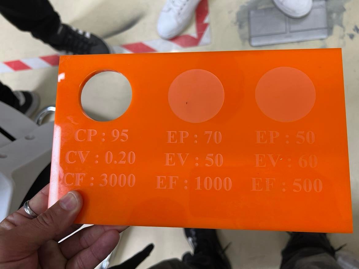
To characterize the laser, the colors were coded to have different powers and velocities in order (frequency constant at 1000) to conduct a comparison study and to create a coupon for the lab. * p = power
-
v = velocity/speed
-
~ (squigly line) = frequency/ pulse of the laser
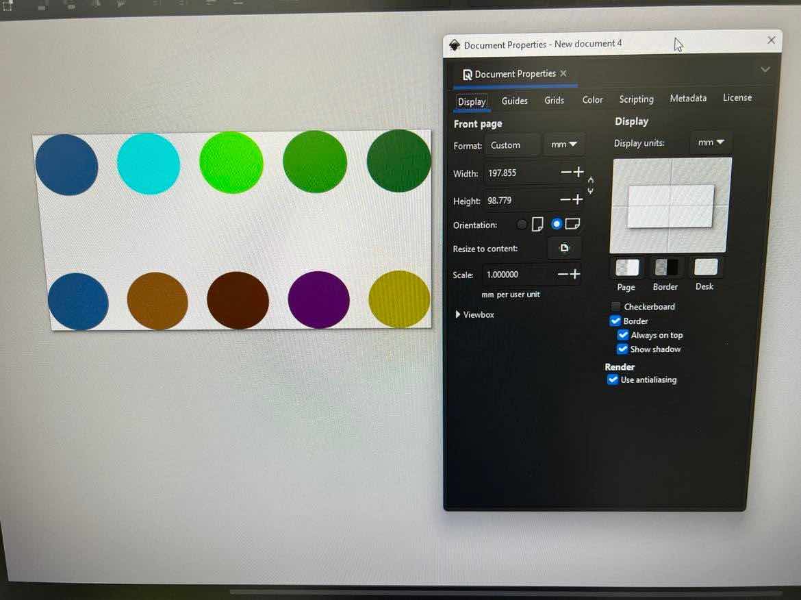
Then in inkscape circles were created with the newly assigned colors. This way time can be saved and can be done in one job.
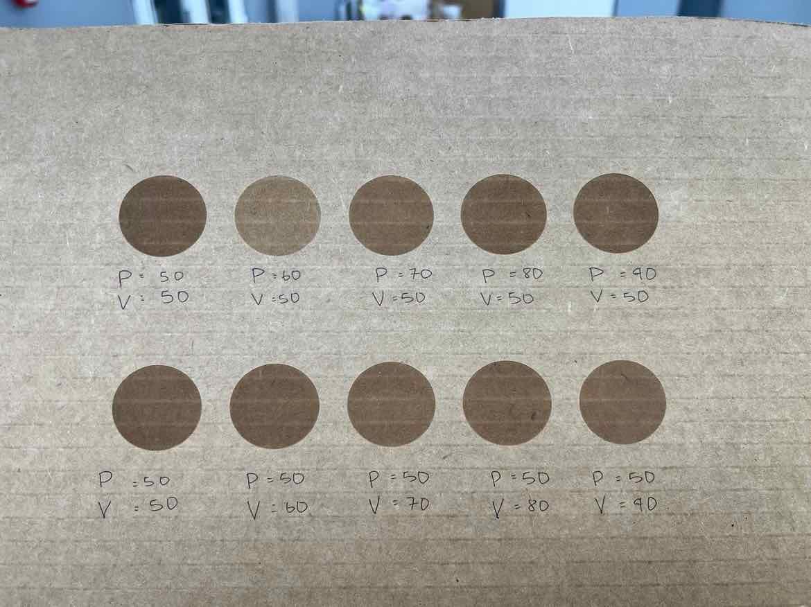
Upon the completion of the job, you can see the different affects of the velocities and powers on the engraving. More power makes it darker. Higher velocities with same power doesn’t engrave as much.
Test on Acrylic:
Part 2
Next to study the kerf and joint clearances, two combs were cut from the same material. Our remote instructor Rico showed us a very useful kerf generation tool which was made by Atsufumi Suzuki a fablab kamakura graduate.
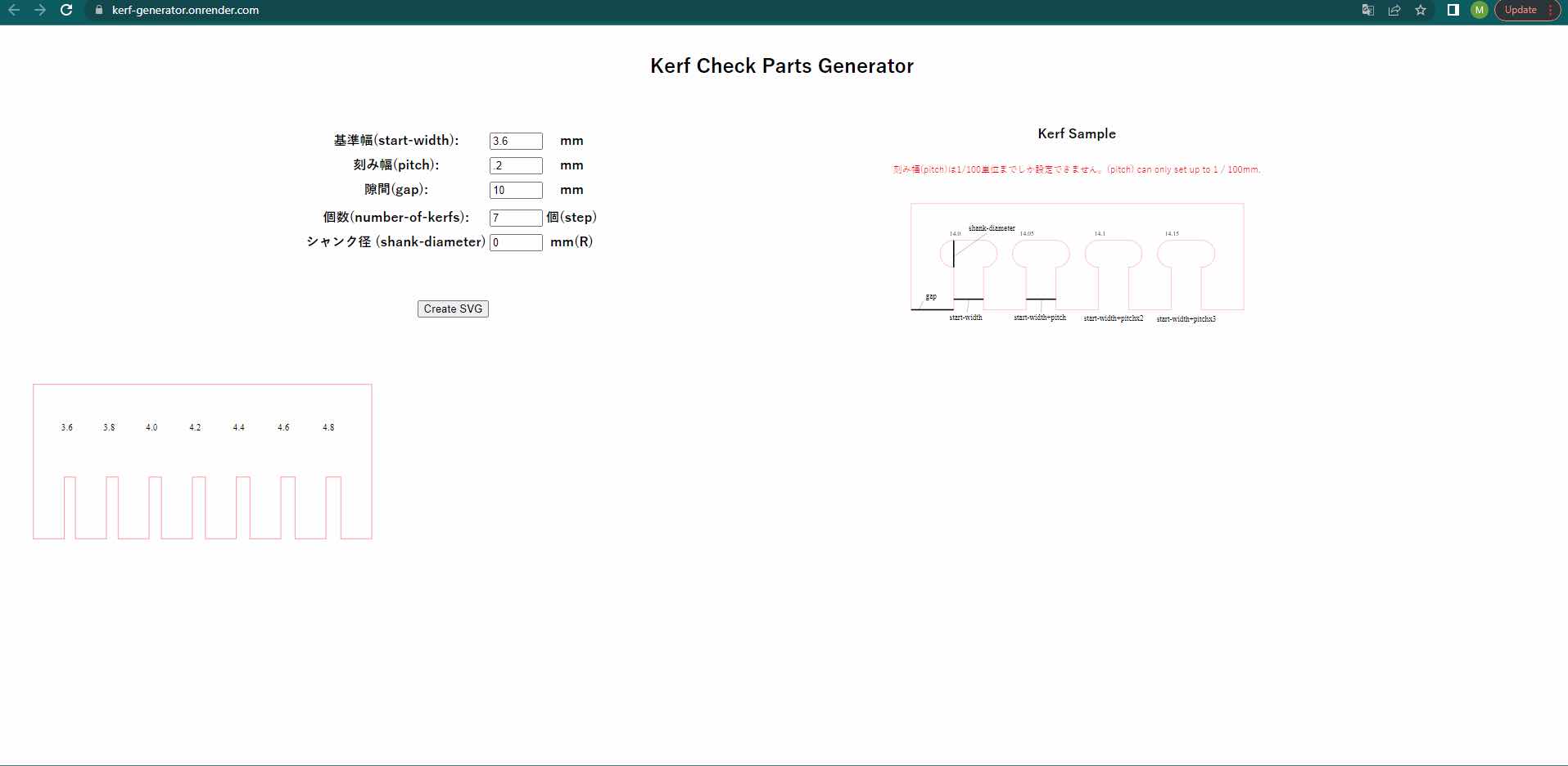
Since the material (cardboard) thickness was about 4.10mm, the comb had gaps ranging from 3.6mm to 4.8 mm, with 0.2 mm increments to determine the best fit. The svg created by the kerf generator tool can be saved and imported into inkscape.
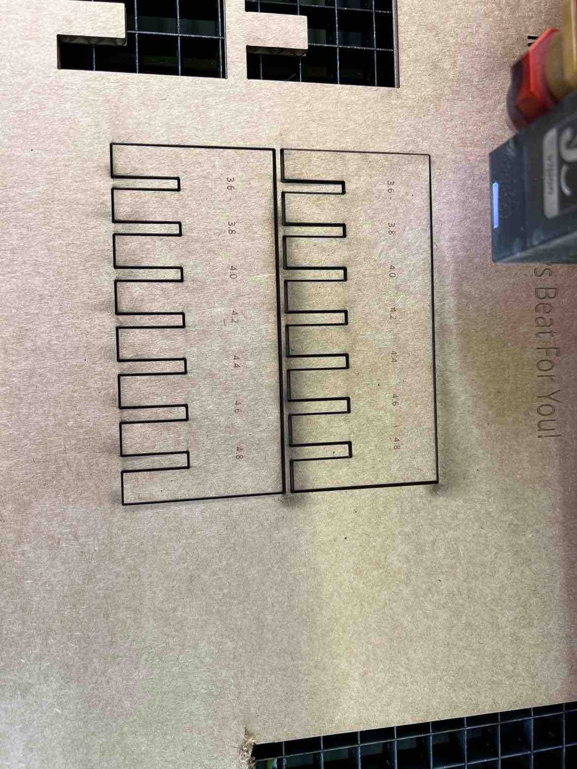
As it can seen, the 3.8mm gap was the best fit so I kept that clearance in mind.
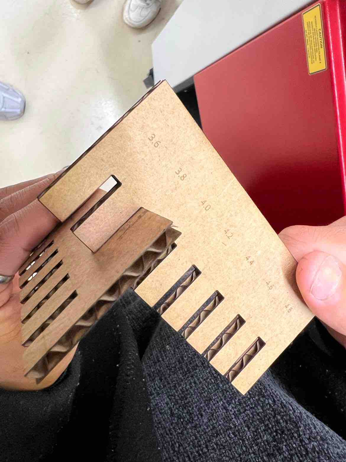
The teeth of the comb all had a designated width of 10mm so I measured all the teeth with a vernier caliper, calculated the difference, averaged them out and divided by 2. The kerf was calculated to be: kerf = 0.15 mm.
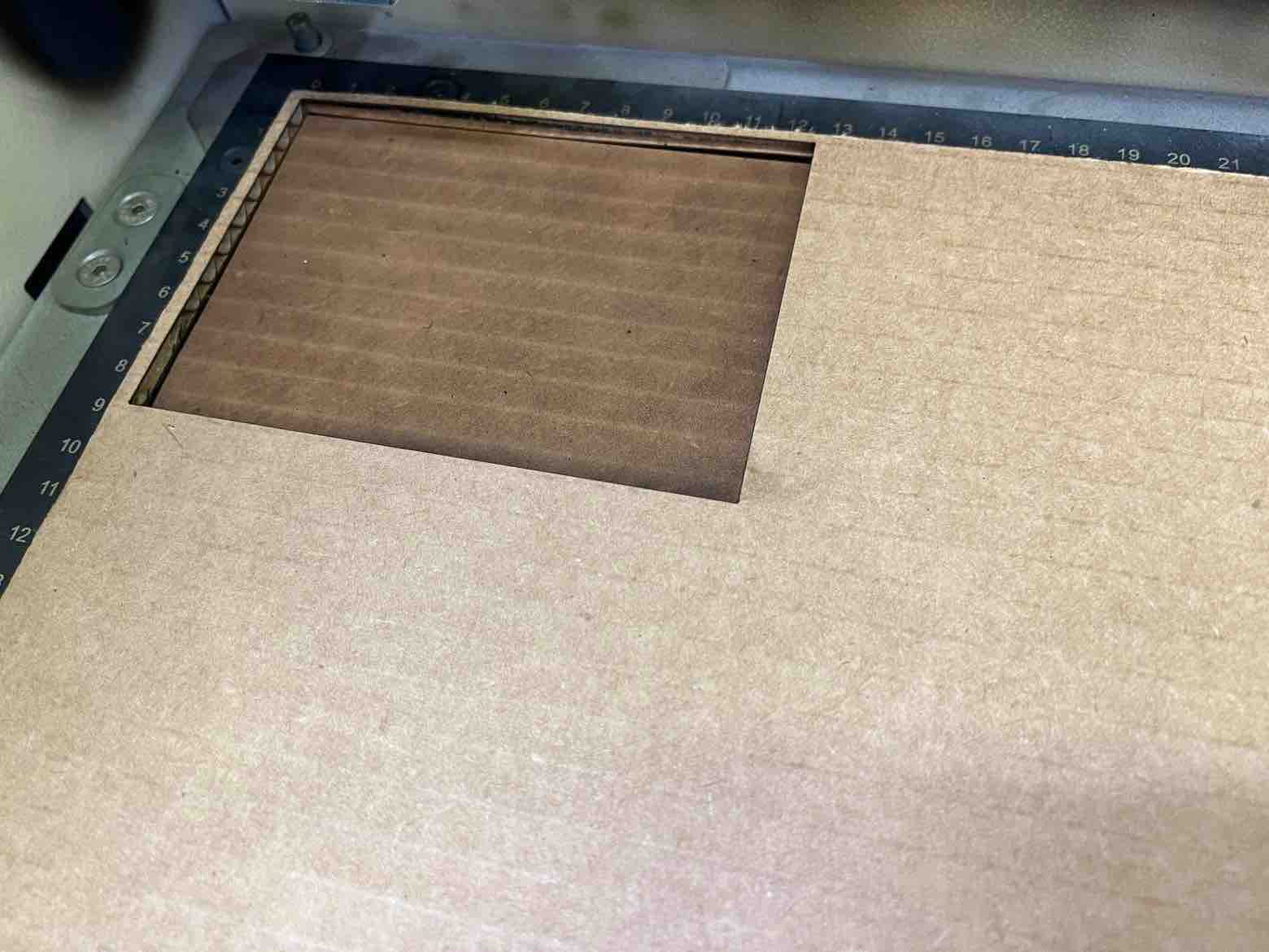
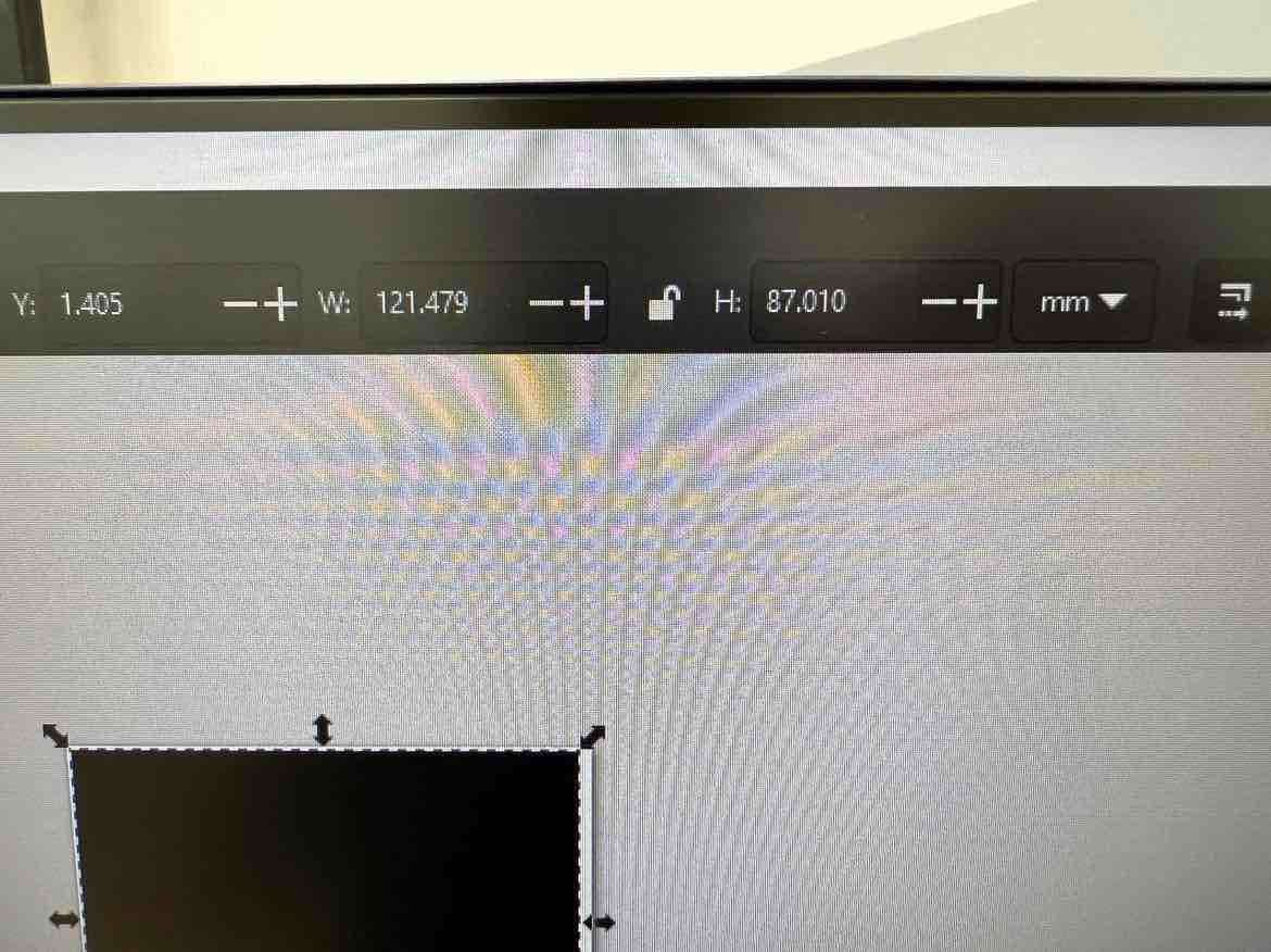
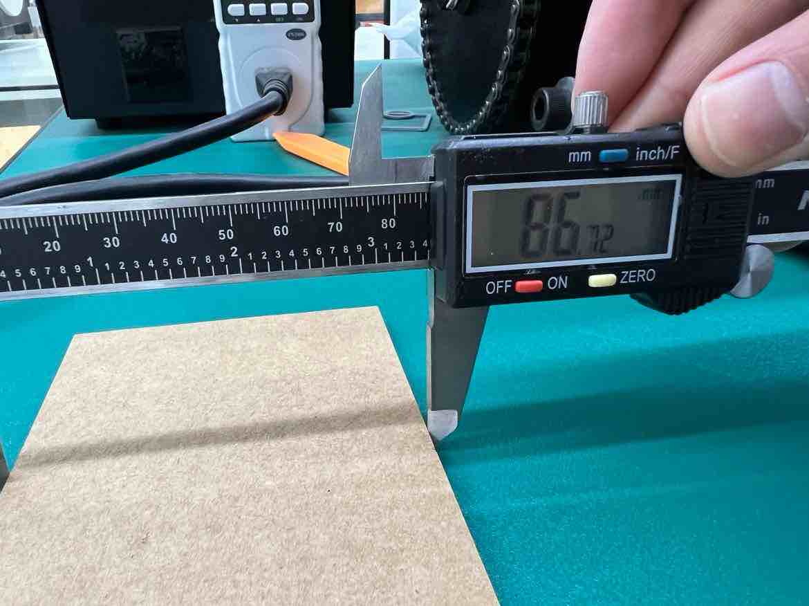
To cross check this, I took the earlier cut rectangle which had a set height of 87.01 mm but the caliper showed a value of 86.72 mm. Its difference divided by 2 returns a value of 0.145mm so it checks out.
- Link to the group assigment (same as above): Group Assignment 1
Some Takeaways:
-
Its good to increase the V vs the power when working with cardboard. High power and lower speed may cause fire. Lower power and higher speeds is a good setting for cardboard
-
Keep the lid closed for a few minutes after the job is complete. So that harmful fumes and smells dissipate
-
While the “hairline” stroke width setting is easier to select, setting the stroke width to “0.001m” is a more reliable practice.
-
Chamber the corner edges for easier fit
Vinyl Cutting
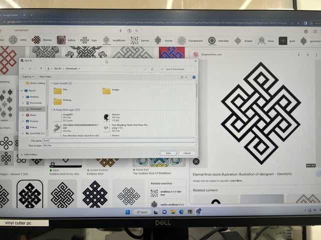
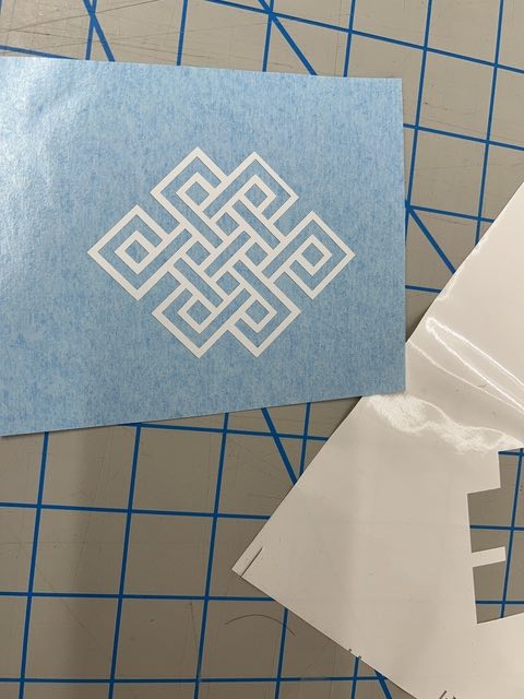
For this weeks vinyl cutting assignment, I cut a sticker for my documentation notebook using the Roland gs-24 vinyl cutter. As we learnt last week, I needed a 2D vector design for vinyl cutting so I began by downloading a png Bhutanese image from knot png and converted it into an svg using Inkscape.
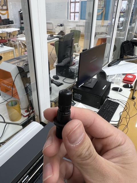
I began with removing the blade holder and checked the blade tip to ensure that it is still in good condition. To remove the blade holder, loosen the yellow knob and open it.
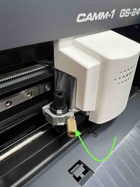
The blade tip should barely be exposed since vinyls are only about a millimeter thick. A good trick is to run your finger over it and the blade should barely be felt.
After checking the tip, materials and connection between the machine and the pc I followed the following workflow to produce my sticker!:
- I turned on the machine by hitting the power button.
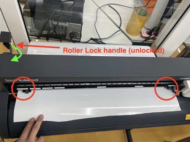
- Then I inserted the vinyl roll from the back ensuring that the rollers were in between the white tapes. The roller handle lock (top left) must be released in order for the rollers to move.
- Once the roll is loaded, select
Rolland hit enter on the machine’s interface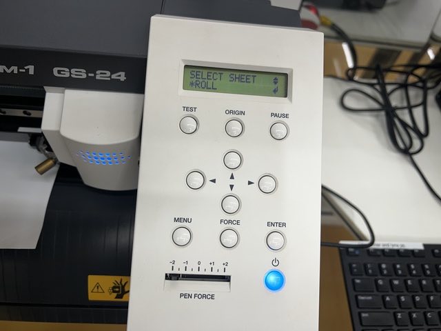
- Then, in inkscape, I imported my png, converted it into a svg with
trace bitmap, and then sent the design into CutStudio by going intoExtension, ->Roland CutStudio->open in CutStudio. CutStudio is the software Roland uses to communicate with the machine. This Step is also possible by using MODS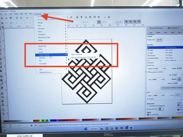
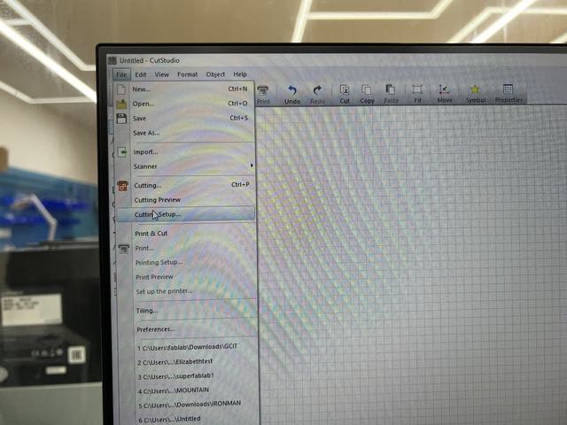
- The design was imported into CutStudio and there I went into File -> Cutting settings, to set up the machine operation
- In Cutting setup, I hit
get from machineto get the material dimensions as well as the machines cutting force settings. Then I hit OK. Here, one can edit the dimensions as well as the cut force.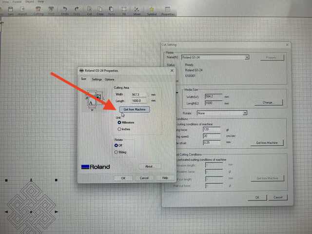
- Then I hit the
Cuttinglogo to finally tell the machine to start cutting.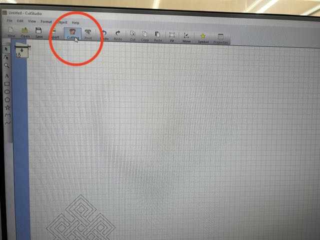
- After hitting the cutting logo, a drop down menu will show up where you can crosscheck the settings and once happy, hit
OKand the cut will begin.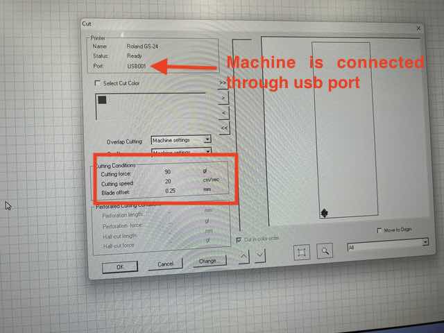
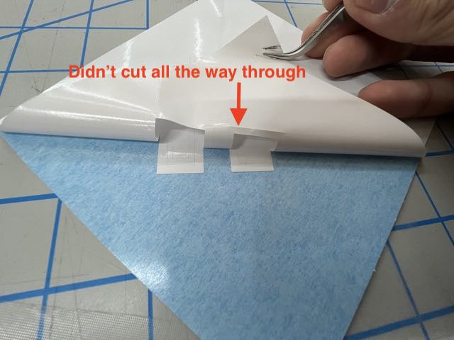
- I cut my design from the main vinyl and set up for weeding with a tweaser. My design didn’t peel off properly unfortunately and it failed because the cutting force of 90 gf is too low (older blade). We had done a test cut and from months of use we knew we had to use 120 gf, but my colleagues wanted me to try with 90 gf to do a check and in hindsight it would’ve been better to test it on a small test cut than a whole design.
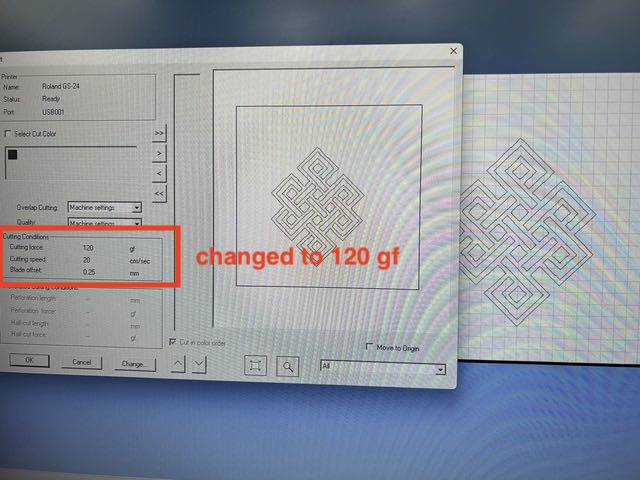
- I went through all the steps again but this time I set the cutting force to 120 gf.
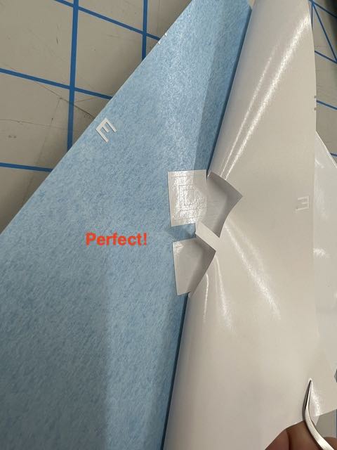
- Successfull cut and weeding:
- Post Weed:
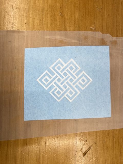
- Then adding masking transfer tape over the design to transfer the design. Make sure to use a squeegee to push the tape onto the design to eliminate air bubbles.
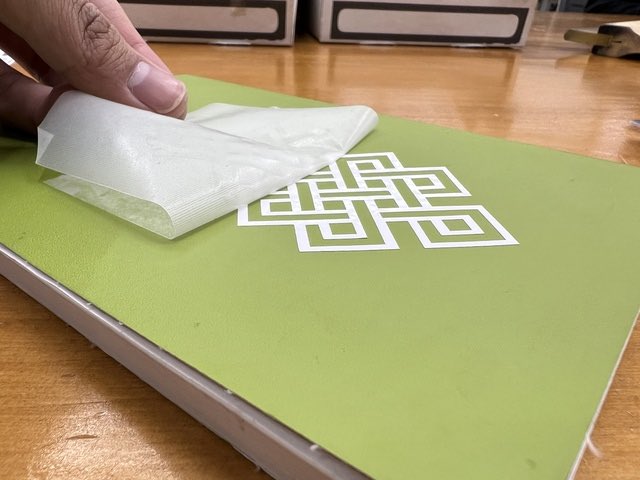
- I Transferred the design onto my notebook, pressed with a squeegee, and using the shearing method to remove the transfer tape.
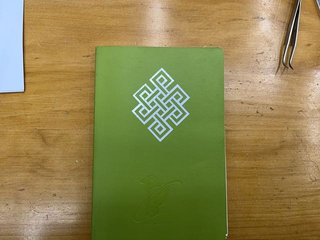
- Final Look!:
Extra: Heat Press
I wanted to mess around with heat transfer vinyl so I used the vinyl cutter to cut my design on a heat transfer vinyl.
The cutout in CutStudio:

I ensured to mirror the image since the design will be printed on the back of the vinyl (not on the shiny part).
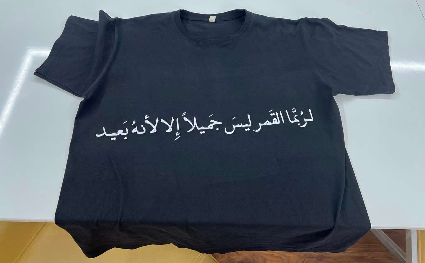
The text is a Quote by Mahmoud Darwish which translates to “Maybe the moon is beautiful only because it is far”
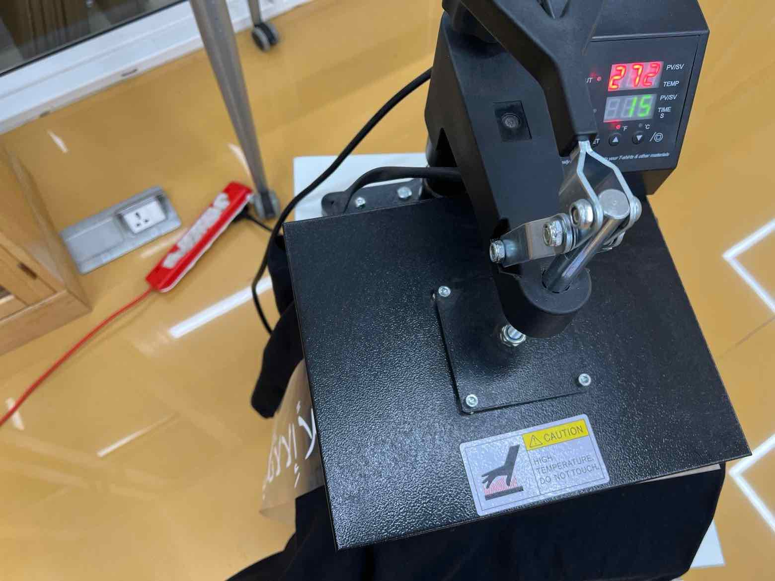
I then turned the heat press machine on and set the temp to 275 F as that was the suggested temp for the vinyl.
I cut the design, weeded it and aligned it where I wanted on my shirt. Then once the heat press machine hit 275F, I placed the shirt with the design in the machine and pressed it for 15 seconds. After which I let it cool for about a minute and then removed the vinyl.
Final Look:
Parametric Construction Kit
Prototype 1
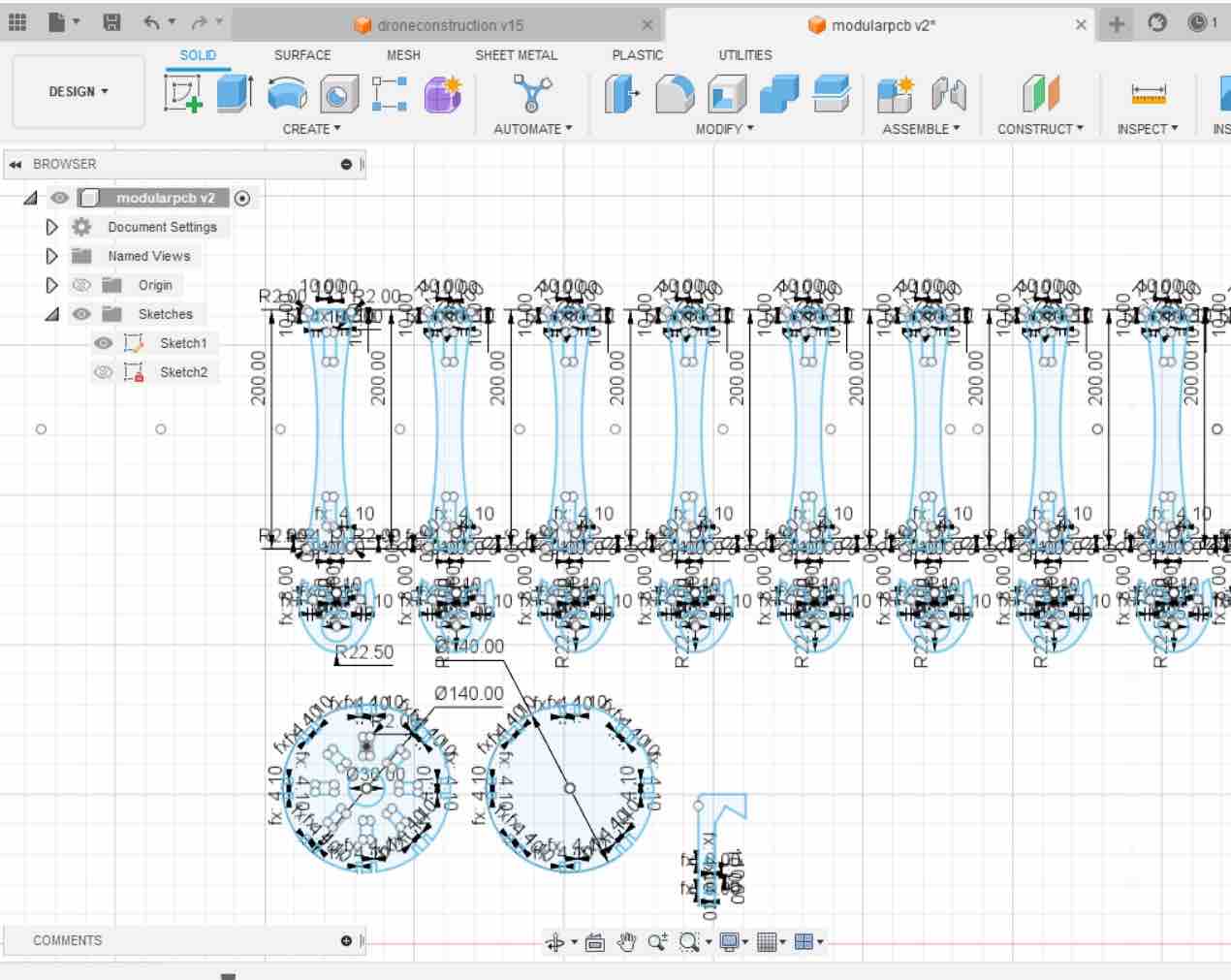
For this assignment I used Fusion360 to design the kit and used the Trotec speedy 400 to laser cut it. I wanted to create a parametric construction kit for a quadcopter drone (modelled after the DJI F450).
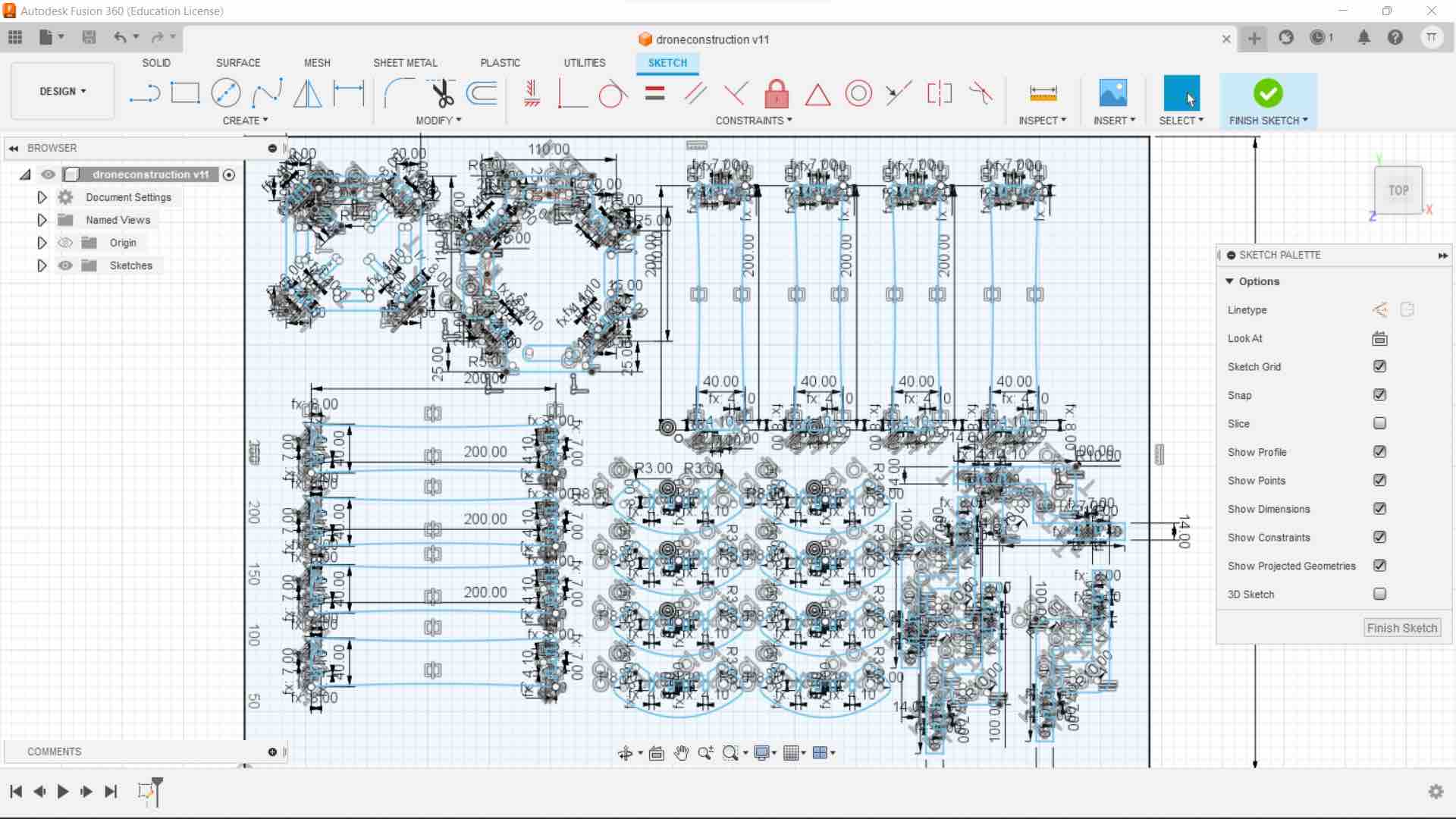
I ensured that I parameterized all the dimensions so that I could always modify the design with ease.
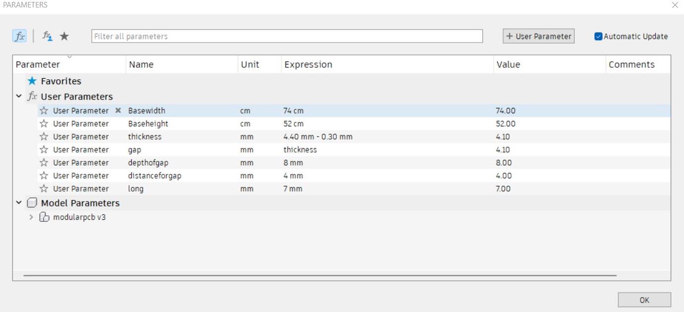
To do this, in Fusion360, I went to modify -> change parameters and + user parameters. In the user papameters, you can edit the parameter name, a numerical value or an expression value and the unit.
There, I added all the dimensions for the following parameters. The main dimensions were the gap, depth of the gap and the distance of the gap. This way I could mainly just change the dimension of the gap after measuring the thickness of the cardboard to ensure proper fit.
I measured my cardboard and it had a thickness of 4.40 mm. Knowing the kerf after characterizing the the Trotec400, I knew I had to adjust the gap accordingly and set it initially to 4.10mm for a proper press fit.
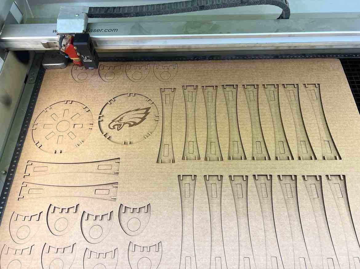
Once happy with the design , I saved my sketch as a dxf, opened it in Inkscape to set the lines color to red (to cut) and the stroke thickness to about 0.01mm and then sent the job to the Trotec JobCenter. The entire workflow of the laser has been documented above when I characterized the Laser.
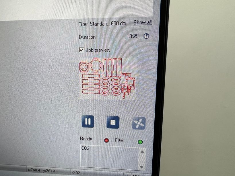
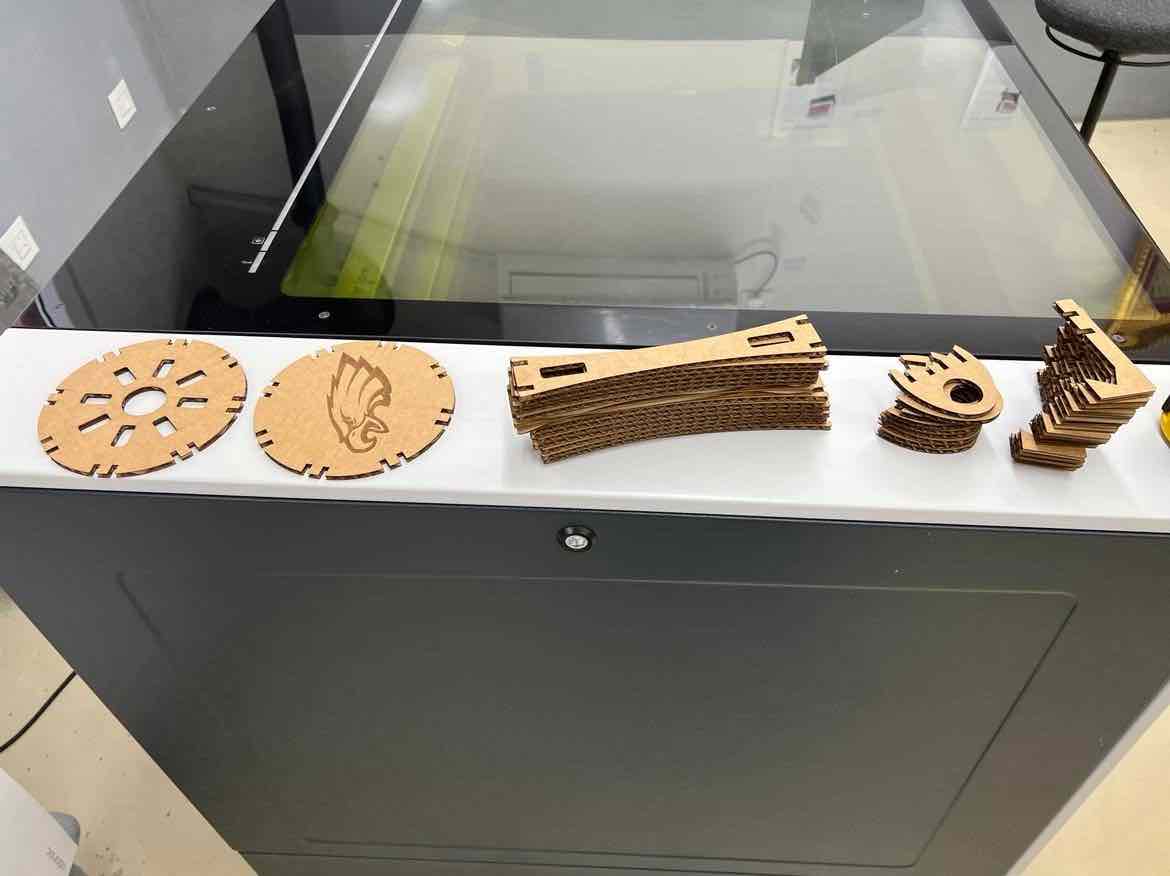
The cardboard once cut:
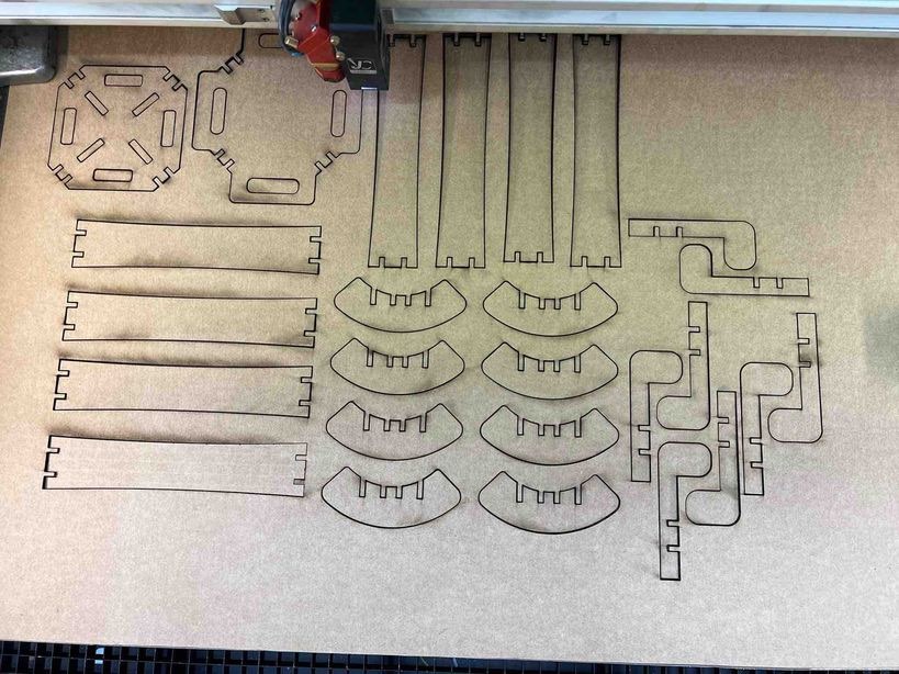
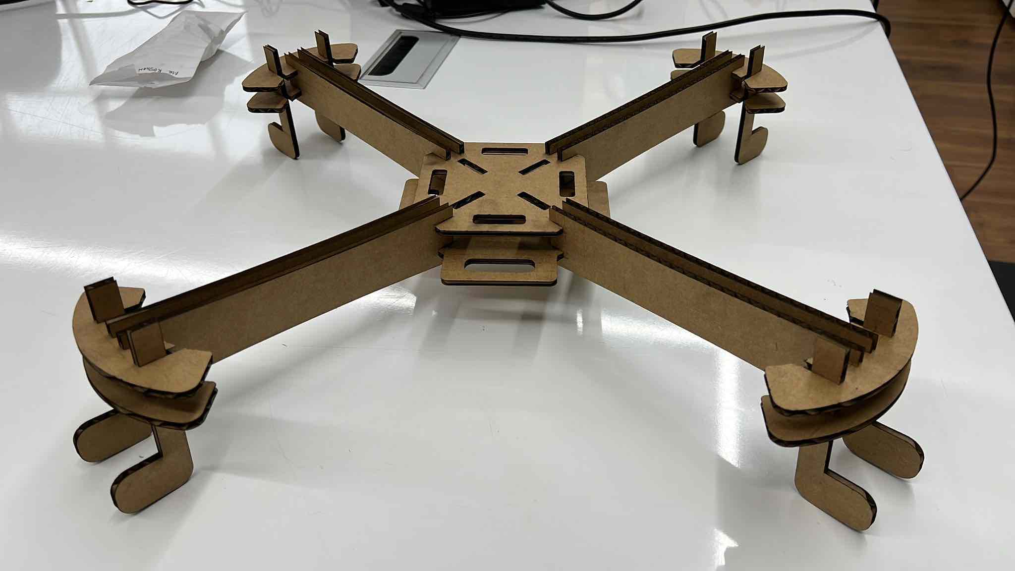
I removed the pieces and assembled the drone. Luckily, my first prototype was a success and all the joints fit fell with proper snugness!
Prototype 2
After working on the first prototype, I was happy with my design but: 1) I knew I could improve the aesthetics 2) I couldn’t really make anything else with the pieces
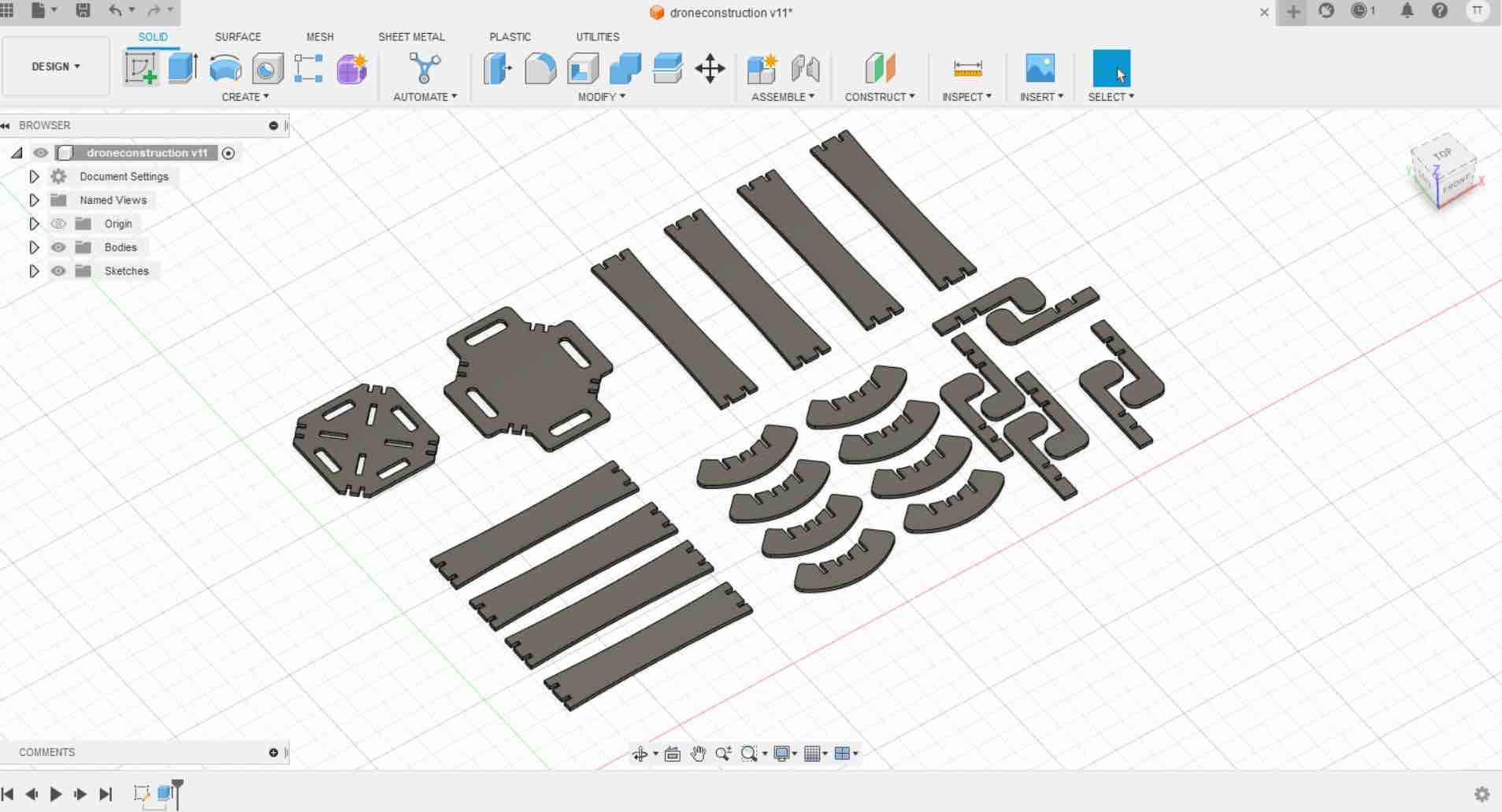
Rico suggested a great idea about modularizing the drone, so the kit can make a different number of multi-rotor drones. Given my experience with modular drone assembly, I was interested by this idea and began working on it, in Fusion360 again. I was reminded of a paper I went through last year titled A multipurpose modular drone with adjustable arms produced via the FDM additive manufacturing process by Brischetto et al, and was used as inspiration.
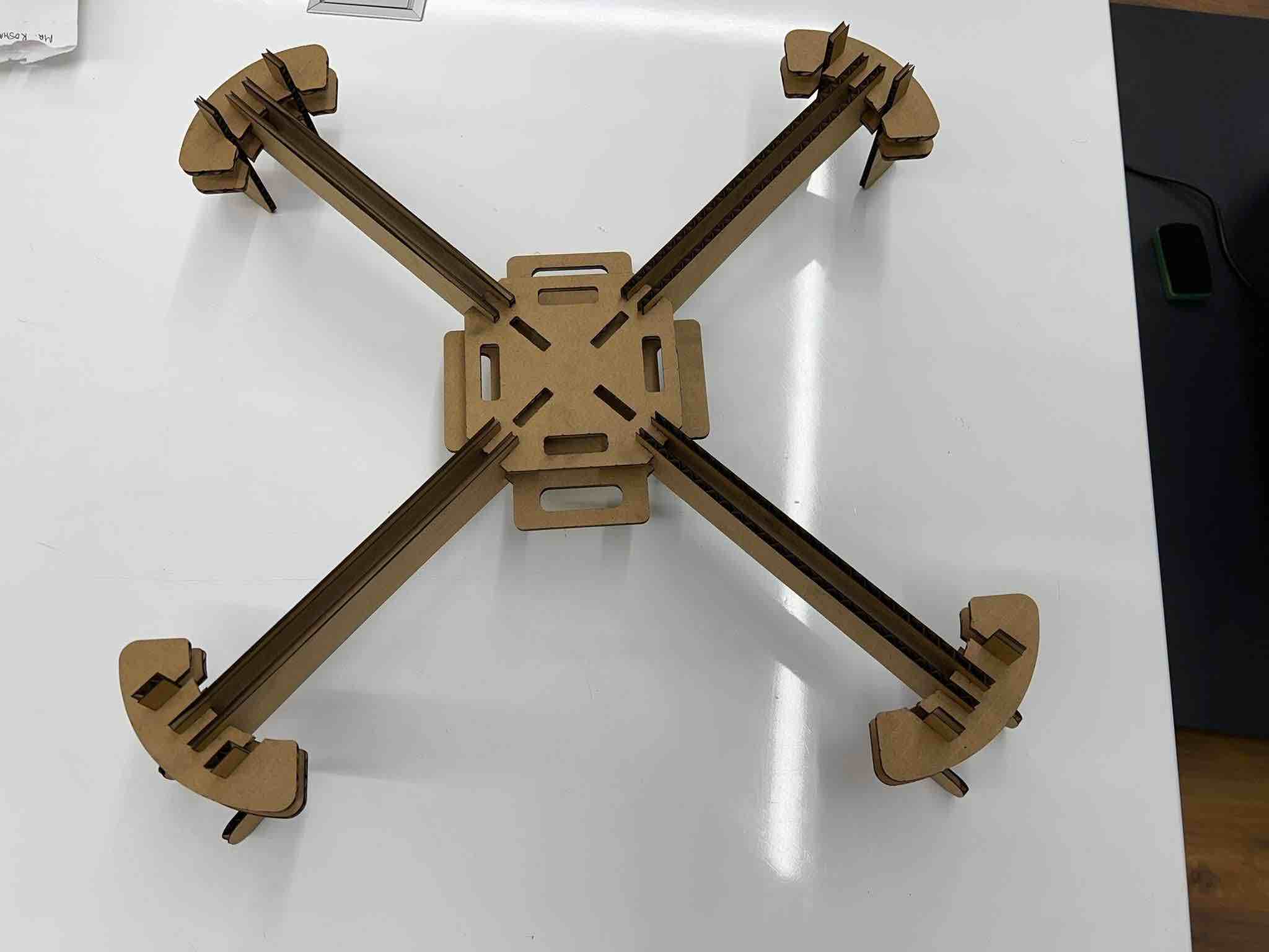
“Hero” Shot of it fully assembled:
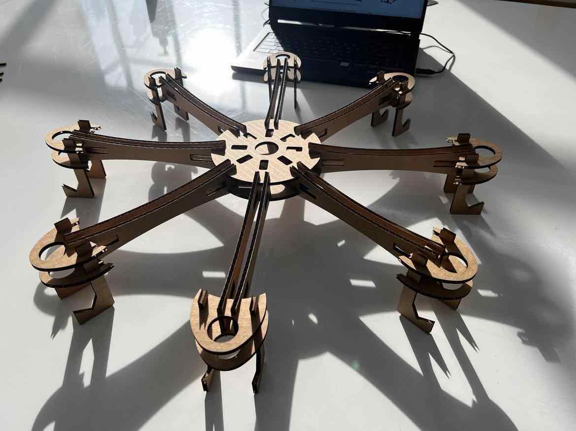
Integrity test of the press-fit joints:
Because the calculations were good, the the parts fit very snug but was also very easy to put together.
The Different Assemblies:
-
Classic Octorotor:
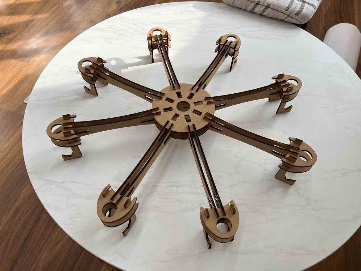
-
Classic Hexarotor:
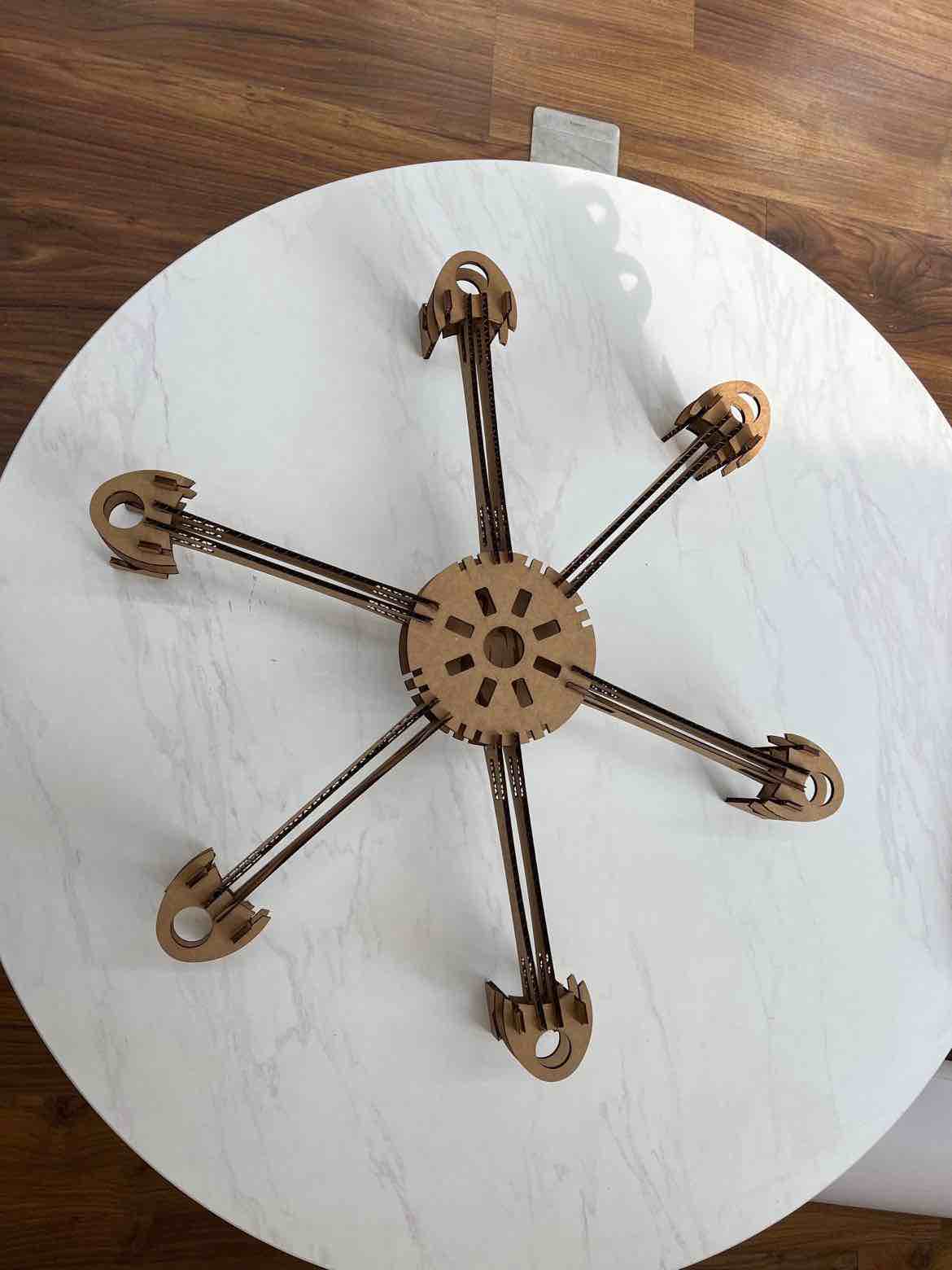
-
Classic Quadrotor:
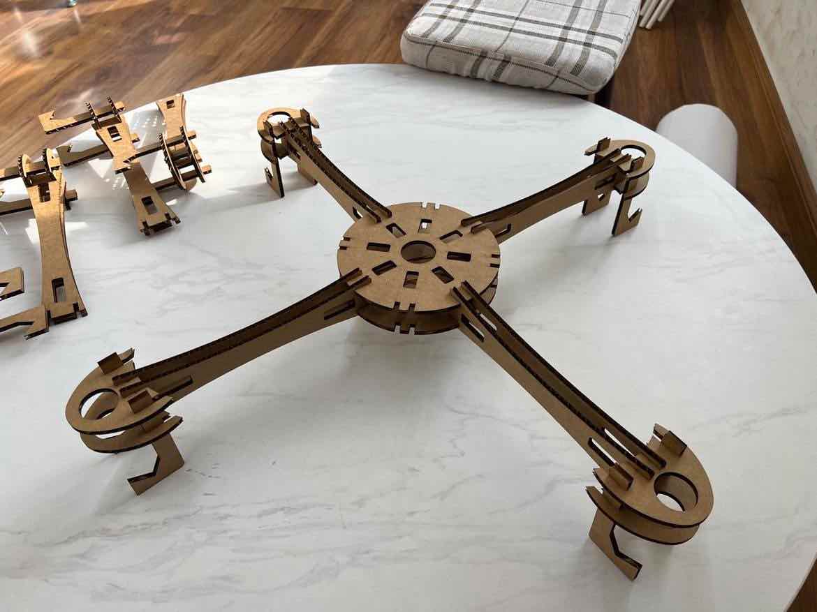
-
Classic Trirotor:
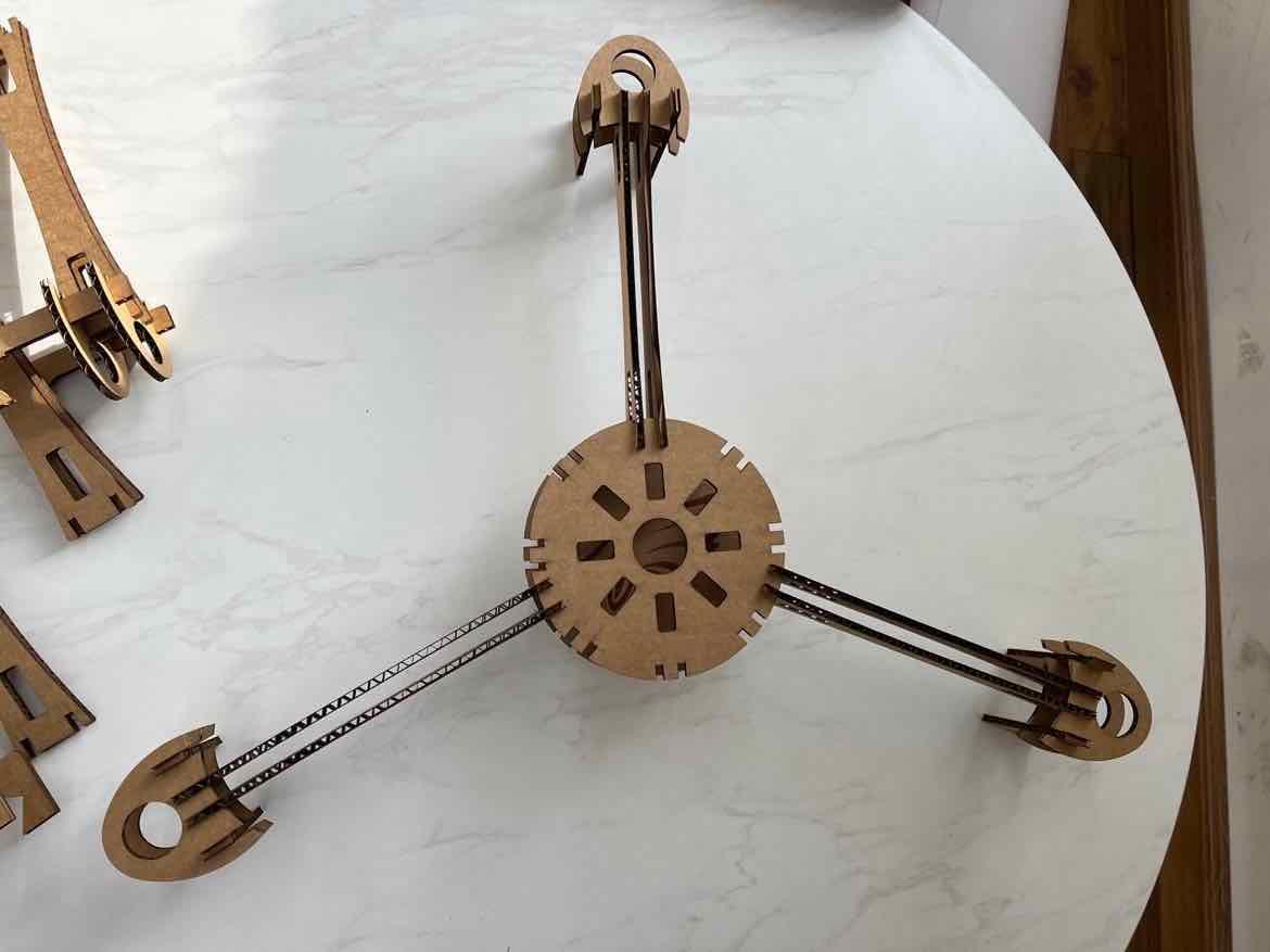
In hindsight, I could’ve added more slots for the proper fitting of the joints for the hexa and trirotors if I actually wanted to use the body for flying. But it still fits on snug but just would not be good during movement.
Design Files: