The Final Project (Main Summary)
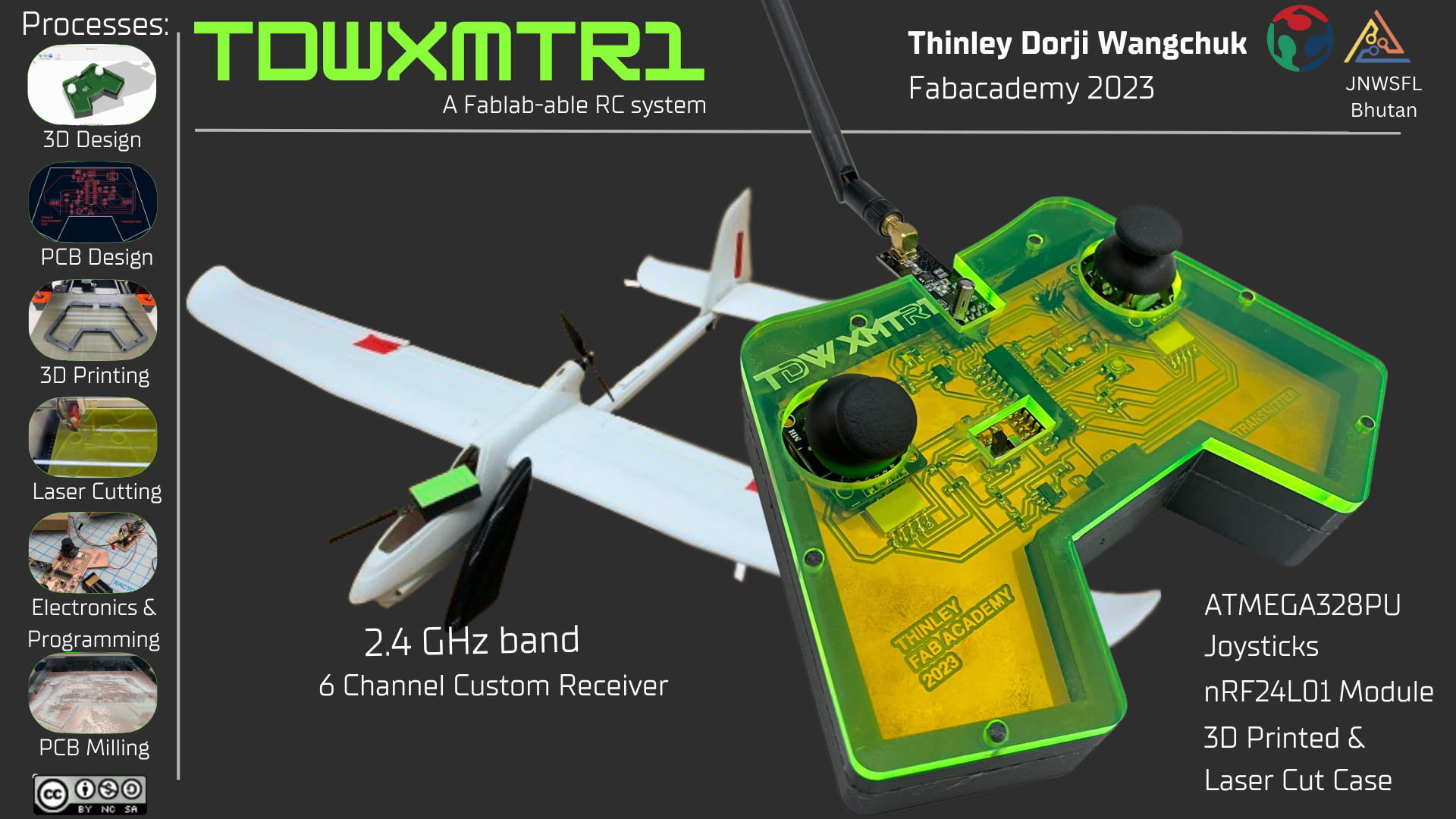
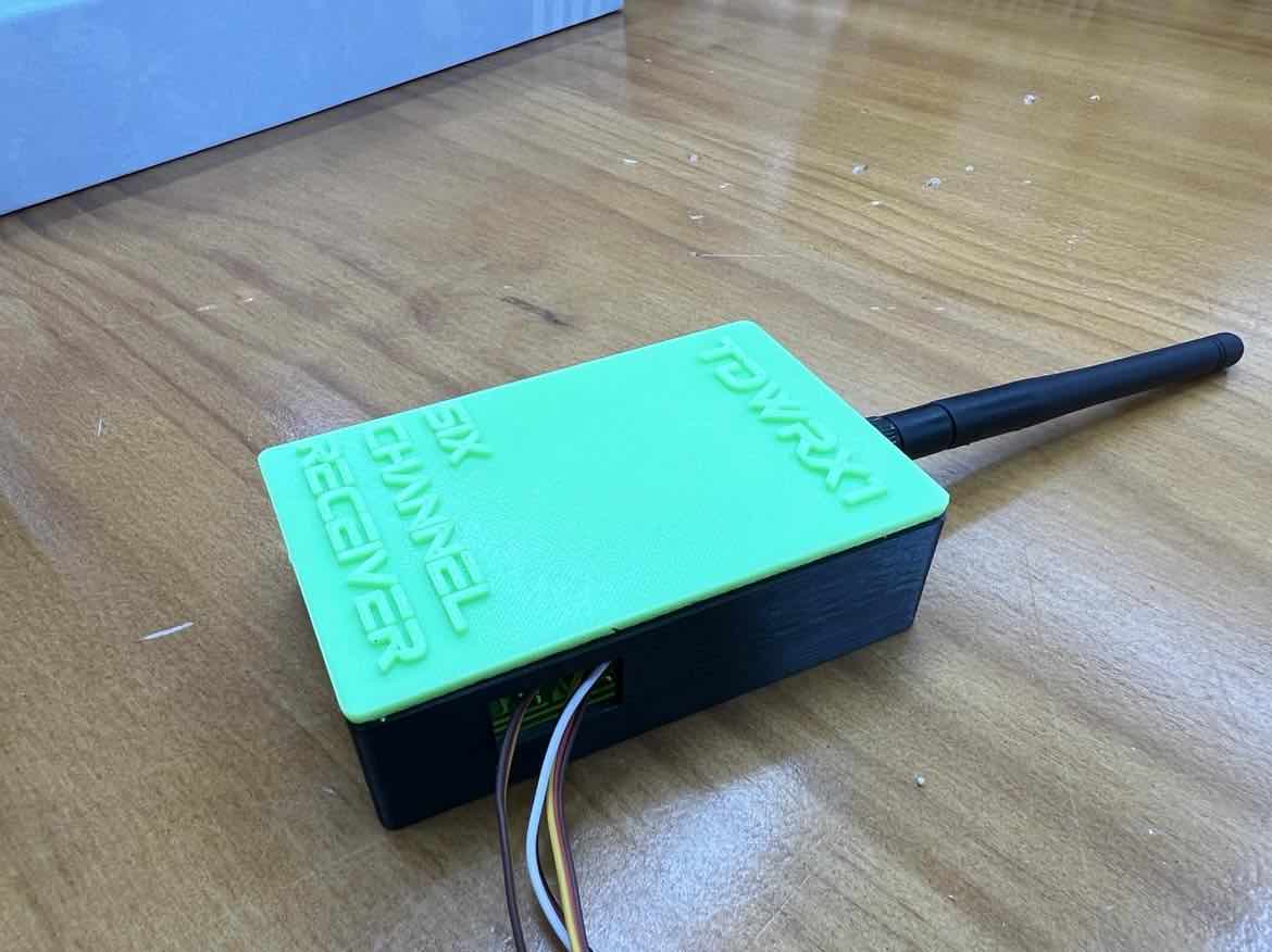
tdwXMTR1: A RC controller for Drones (and other things)
For my Final Project, I decided to create a fablab-able Radio frequency based RC Joystick Transmitter that is controlled by the ATmega328PU. Along with this, I also created a 6 Channel receiver with I2C capabilities that also runs on the Atmega328PU to receive communication from my transmitter. The nRF24L01 modules are used for the 2.4GHz radio communication.
Final Video
Final Slide
Electronic Design and Production
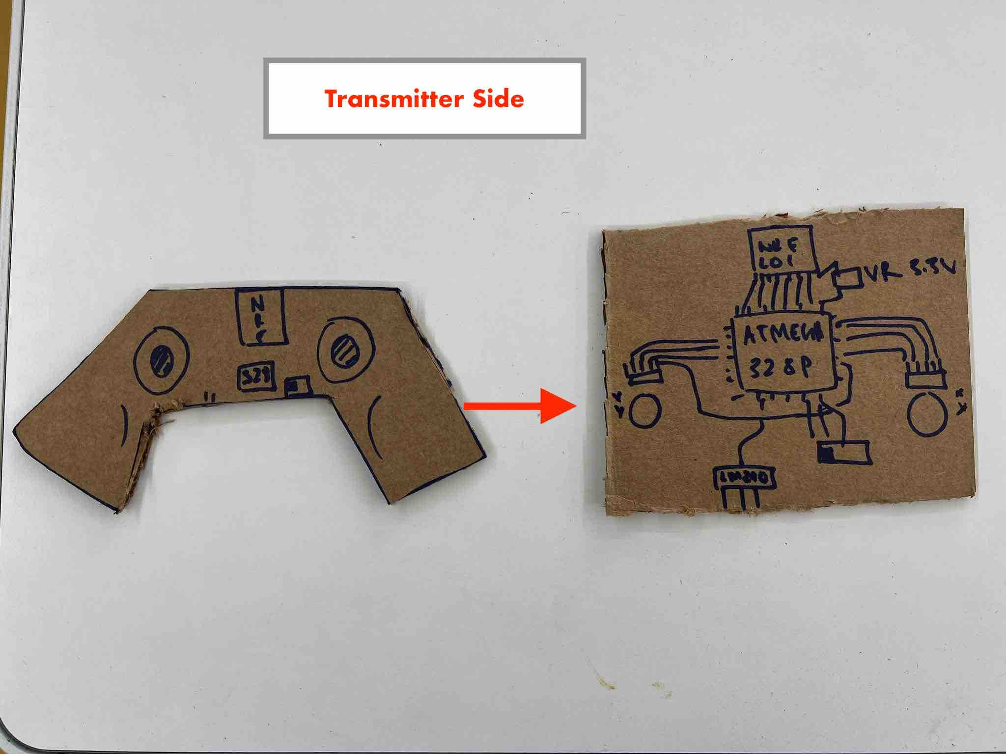
Transmitter Board
I began by mocking up the design on cardboard by hand to get better a better idea of how I needed my connections to work.
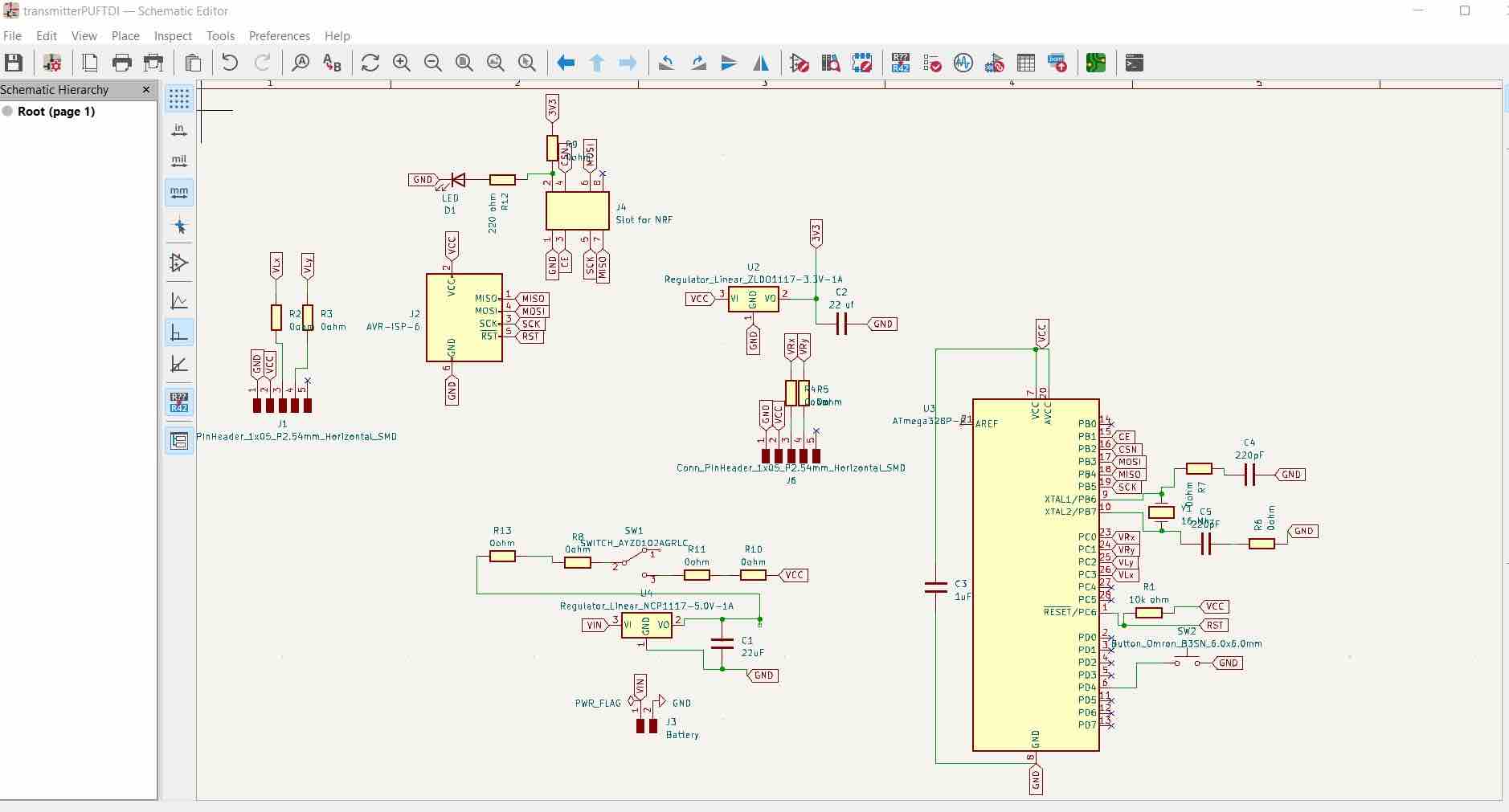
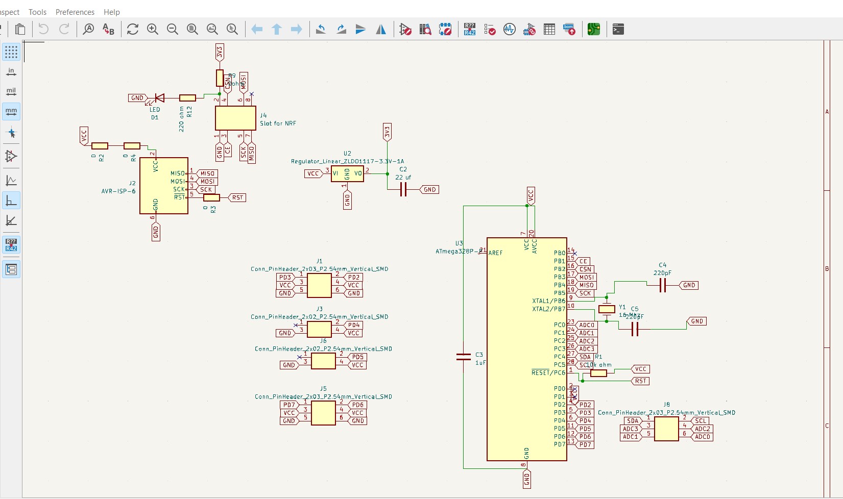
Then I moved onto Kicad and began designing the Schematic.
Final schematic:

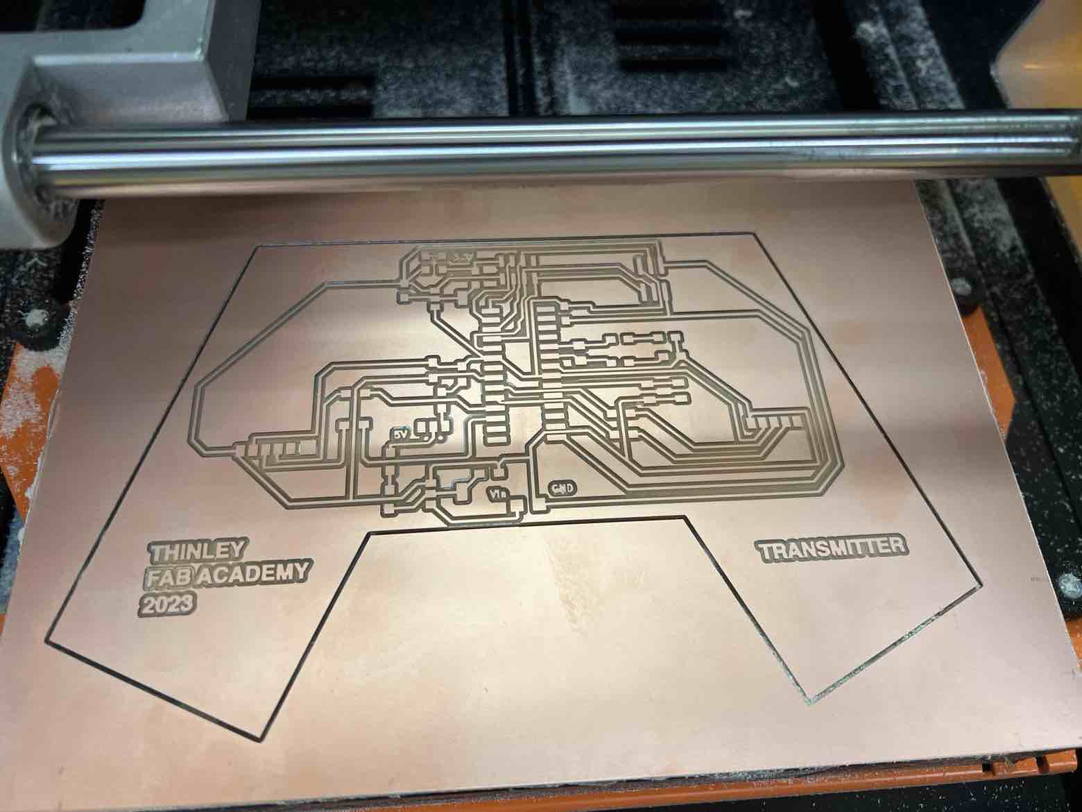
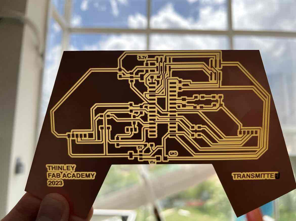
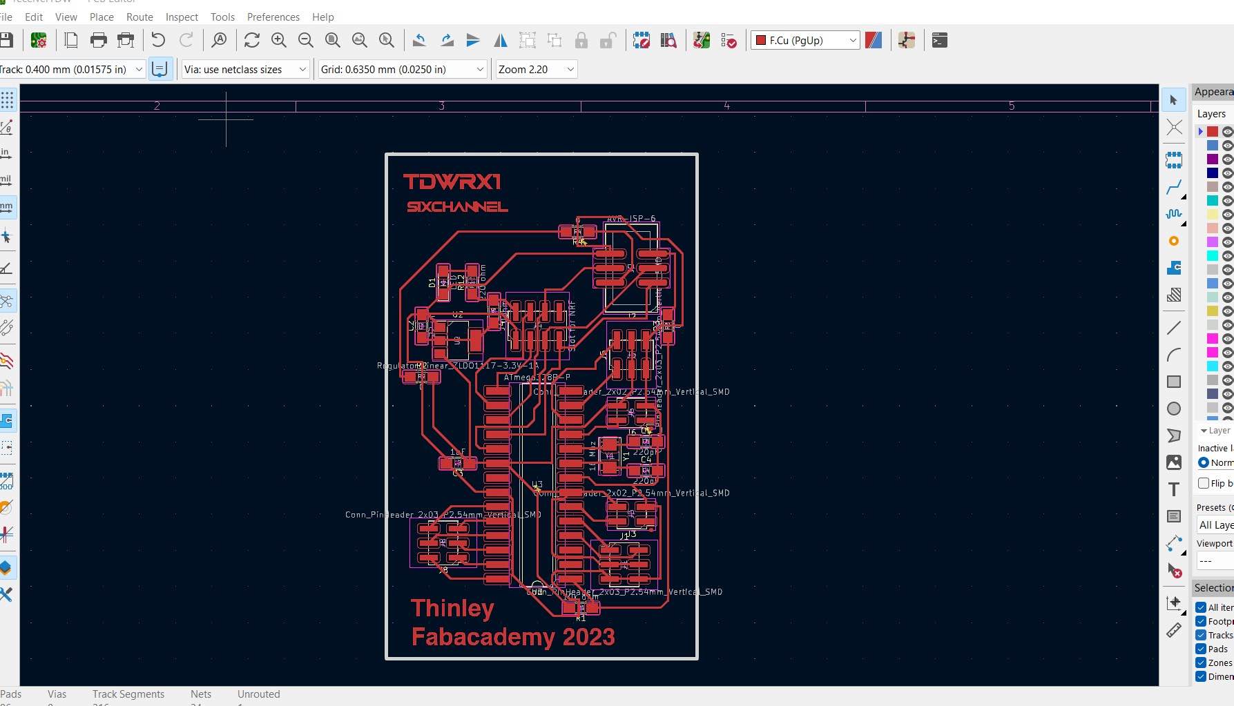
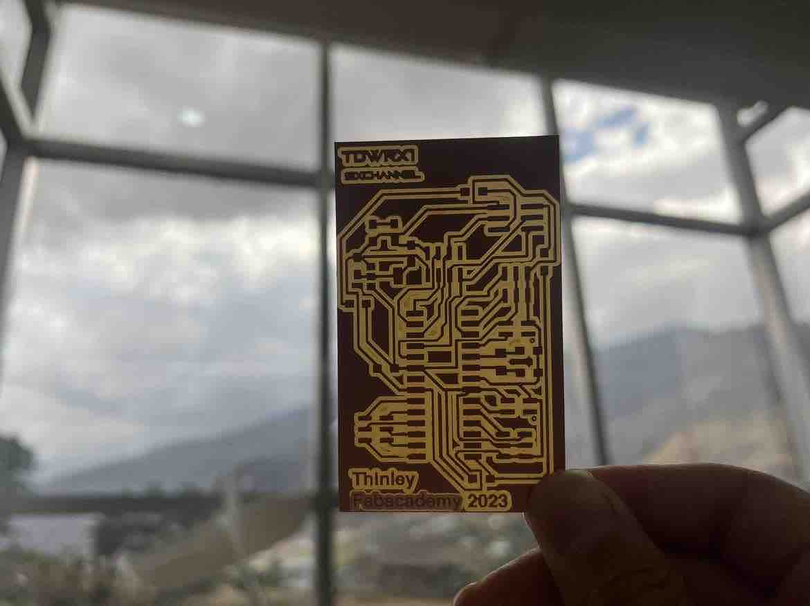
Final PCB:
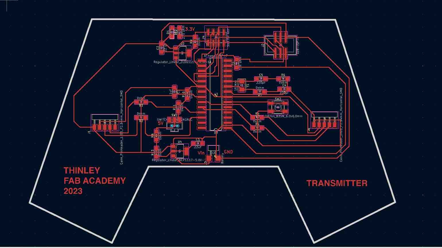
I took the svgs from Kicad into inkscape to convert them to pngs. Then I used mods to obtain my rml to run the Job.
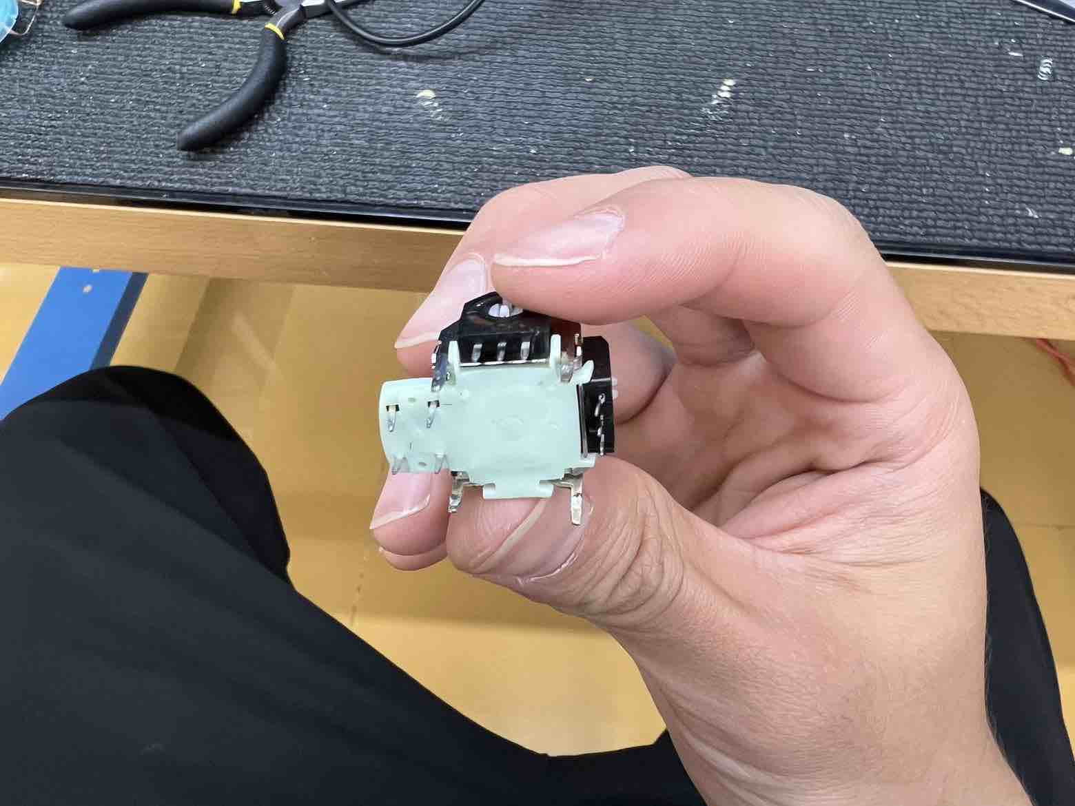
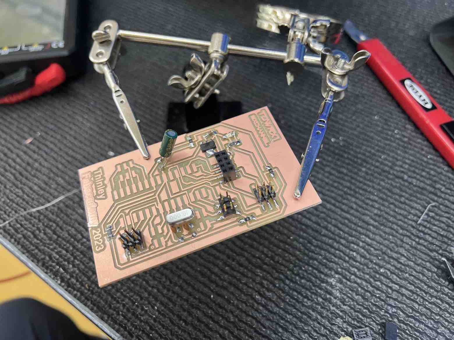
Soldered:
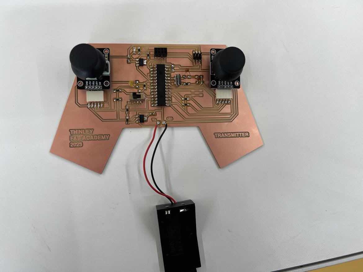
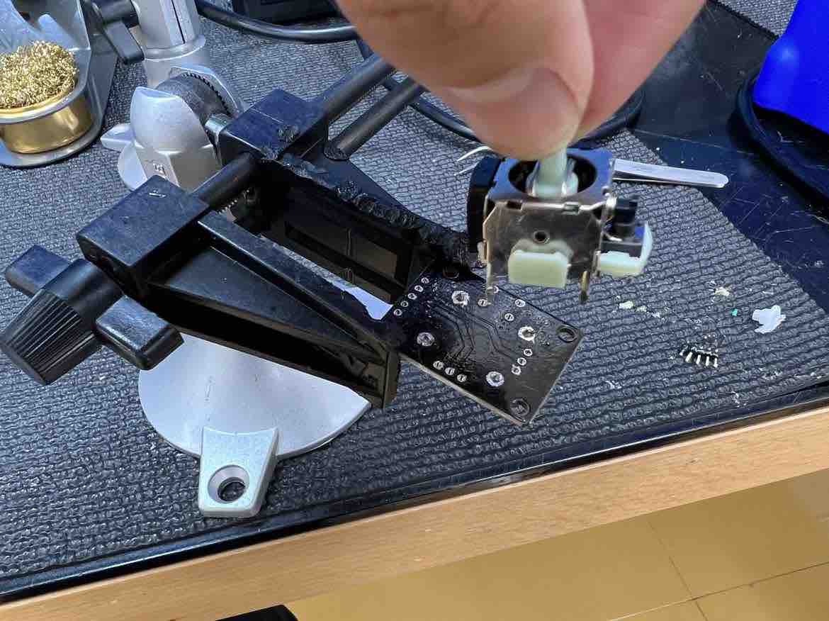
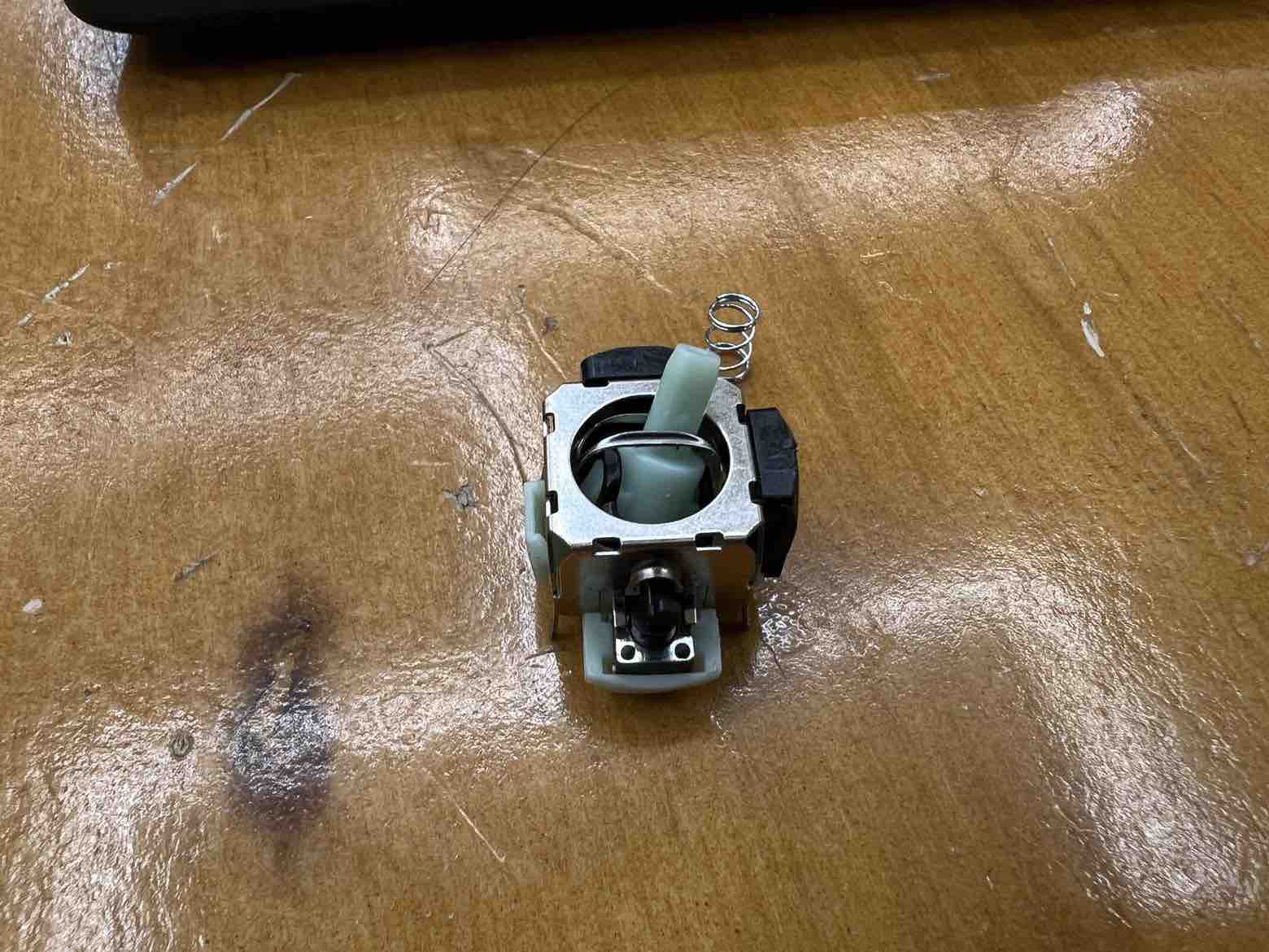
I had to desoldered and resolder the connection pins on the joystick for ease of connection onto the board. I also resoldered the left joystick to remove its internal spring and then resoldered it back together.
For a more in depth look into my design and all my work, please check out my Electronics and Production page under Final Project
Receiver Board
Just like the transmitter board, I used kicad and began the schematic design.
My RX board:
sch:
pcb:
I went ahead and Milled on the Roland SRM20:
And then Soldered all the components:
Final board with the MCU holder:

the board testing can be found in Programming.
For a more in depth look into my design and all my work, please check out my Electronics and Production page under Final Project
Programming
After design and production of the Transmitter and Receiver boards, I moved on to the programming side of things, for communication between the two.
In the Arduino IDE, I ensured that I had downloaded the three crucial libraries for both sets of codes. They are:
Programming was a bit tricker since they were custom boards made by me and I had to do a lot of research on burning the bootloader and programming the atmega328p chip. Before programming the atmega328p chip, its bootloader needs to be burnt, just an extra step to keep in mind.
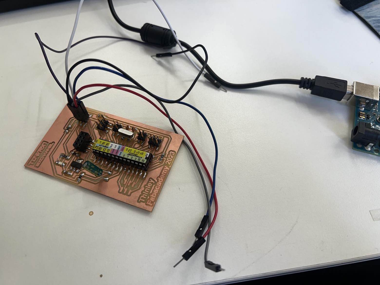
I used an external Arduino uno dev board to program my transmitter (atmega328p) using the ISP.
First, I opened the ArduinoISP code from under examples and uploaded the code to the Arduino Uno (the programmer). I waited for the upload to finish.
Then, I followed the following diagram to connect my board (target) to the arduino:
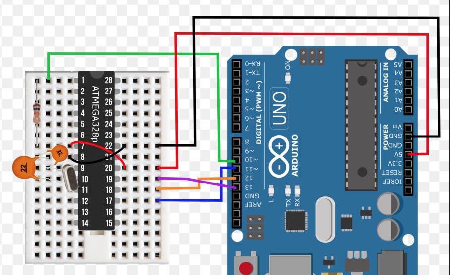
Then in the Arduino IDE, under tools select the board -> Arduino Uno, select the correct COM port, programmer -> arduino as ISP and then I hit burn bootloader found under the tools section.
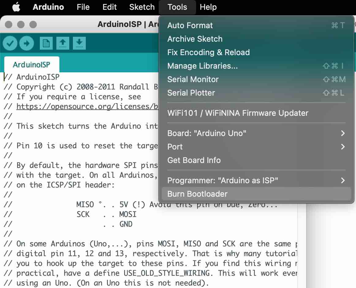
This will take a bit. the IDE will tell you when its done burning. Your custom board with the ATMGEA328p is now burnt.
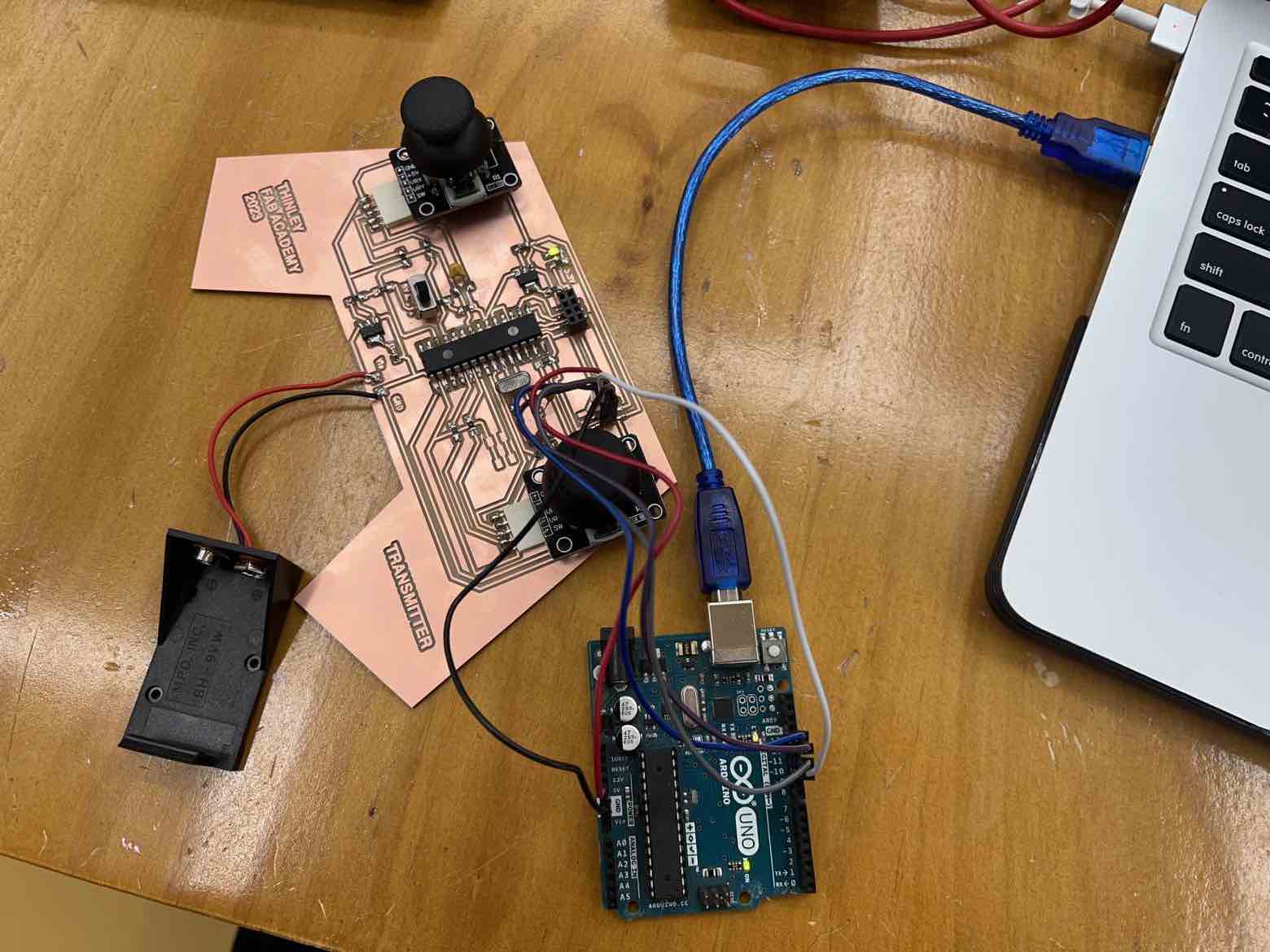
Next to upload the transmitter code, first I opened the code and edited for how I want my code to run. This included adding more channels, defining the initial values of the potentiometers, attaching the channels, setting the correct pins which were linked to throttle, pitch, roll and yaw, and ensuring proper direction of the joystick was set (up to increase throttle, down to decrease).
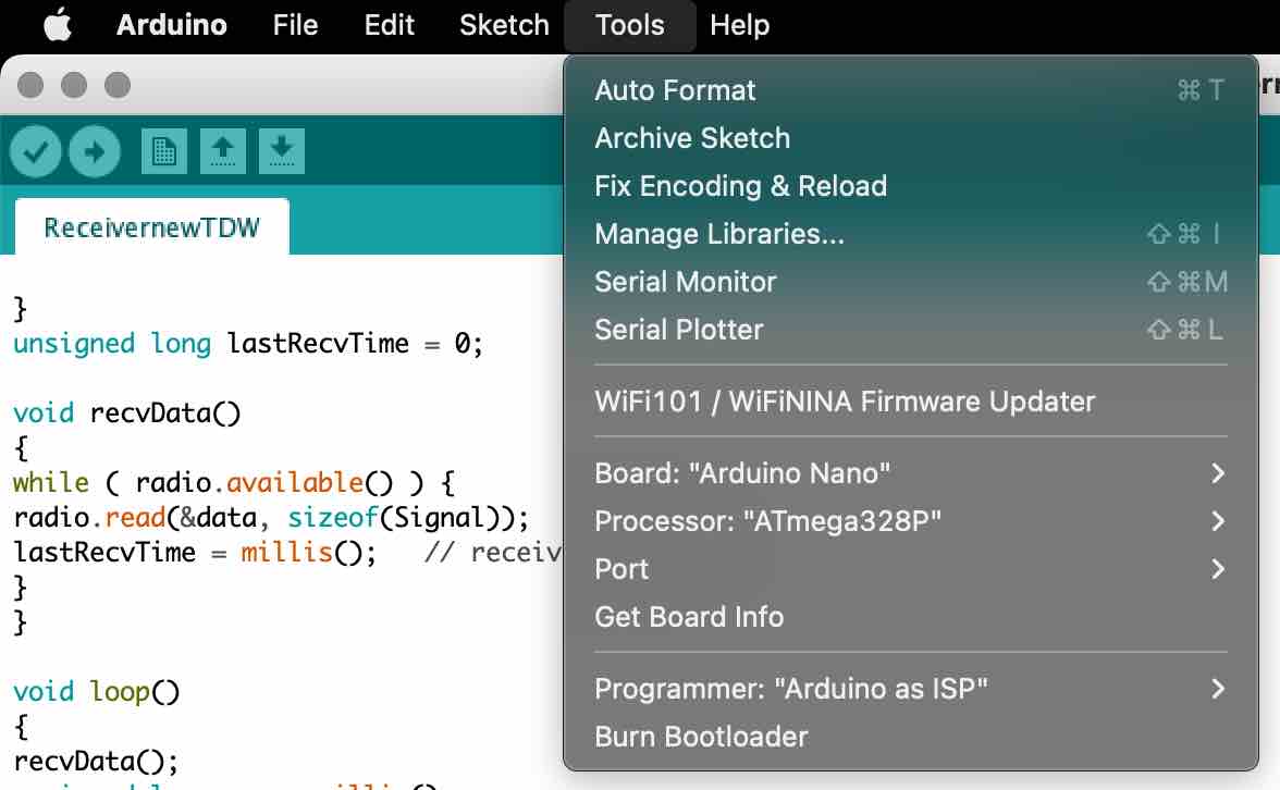
Then, I changed the board to nano, processor to atmega328p, the correct port and kept Arduino as ISP.
The final step is the most crucial. After compiling your code as usual, do not upload using the typical upload button as is usually done. Instead, I went to Sketch and selected Upload using programmer. This will upload the code to your board using the arduino Uno without the code uploading to the Uno.
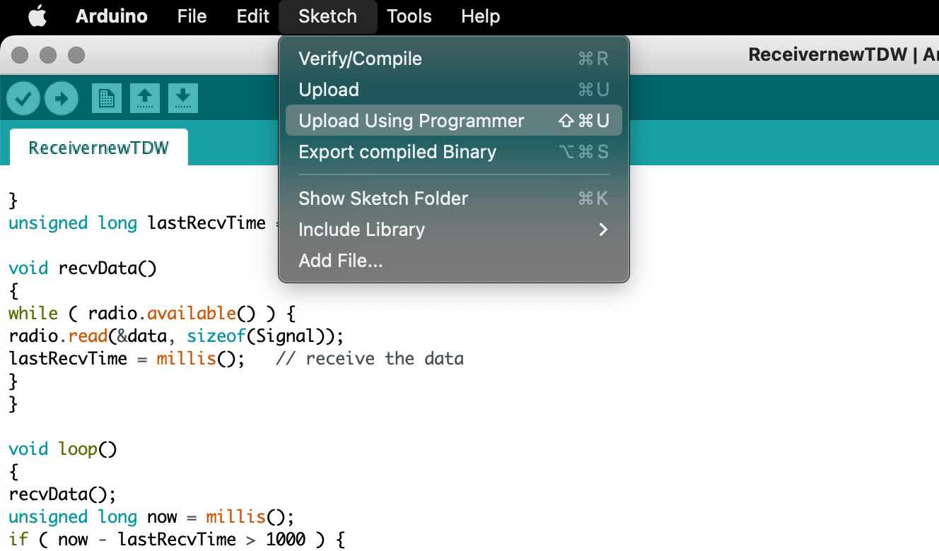
I successfully burnt my boards’ boot loader and succesfully uploaded the code.
the code:
// original code:4 Channel Transmitter by KendinYap
// Customized and edited by Thinley Wangchuk Fabacademy 2023
// 6 Channels

#include <SPI.h>
#include <nRF24L01.h>
#include <RF24.h>

const uint64_t pipeOut = 0xE9E8F0F0E1LL;   //IMPORTANT: has to be the same as in the receiver 0xE9E8F0F0E1LL
RF24 radio(9, 10); // select CE,CSN pin

struct Signal {
byte throttle;
byte pitch;
byte roll;
byte yaw;
byte aux1;
byte aux2;
};

Signal data;

void ResetData()
{
data.throttle = 0; // Motor Stop (254/2=127)| Motor (Signal lost position )
data.pitch = 127; // Center  (Signal lost position)
data.roll = 127; // Center  (Signal lost position )
data.yaw = 127; // Center  (Signal lost position)
data.aux1 = 127;    // Center (Signal lost position)
data.aux2 = 127;    // Center (Signal lost position
}

void setup()
{
//Start everything up


radio.begin();
radio.openWritingPipe(pipeOut);
radio.setAutoAck(false);
radio.setDataRate(RF24_250KBPS);
radio.setPALevel(RF24_PA_HIGH);
radio.stopListening(); //start the radio comunication for Transmitter
ResetData();

}

void loop()
{

/*If your channel is reversed, just swap 0 to 255 by 255 to 0 below
EXAMPLE:
Normal:    data.ch1 = map( analogRead(A0), 0, 1024, 0, 255);
Reversed:  data.ch1 = map( analogRead(A0), 0, 1024, 255, 0);  */

/* The two channels to which the servos are linked to may need their Analog input pin declarations swapped for the correct roll directions.
Such as "(A1)" being swapped with "(A0)" or vice versa, all below.*/

data.throttle = map( analogRead(A3), 0, 1024, 0, 255 );
data.roll = map( analogRead(A1), 0, 1024, 0, 255 );
data.pitch = map( analogRead(A0), 0, 1024, 0, 255 );
data.yaw = map( analogRead(A2), 0, 1024, 0, 255 );

data.aux1 = map( analogRead(A6), 0, 1024, 0, 255);
data.aux2 = map( analogRead(A7), 0, 1024, 0, 255 );
radio.write(&data, sizeof(Signal));
}
To program the receiver, I used the method of burning the bootloader and uploading the program by using a Arduino as explained above.
the code:
//  4 Channel Receiver from KedinYAP.
//  PWM output on pins D2, D3, D4, D5,D6,D7
// Customized by Thinley wangchuk fabacademy 2023

#include <SPI.h>
#include <nRF24L01.h>
#include <RF24.h>
#include <Servo.h>

int ch_width_1 = 0;
int ch_width_2 = 0;
int ch_width_3 = 0;
int ch_width_4 = 0;
int ch_width_5 = 0;
int ch_width_6 = 0;

Servo ch1;
Servo ch2;
Servo ch3;
Servo ch4;
Servo ch5;
Servo ch6;

struct Signal {
byte throttle;
byte pitch;
byte roll;
byte yaw;
byte aux1;
byte aux2;
};

Signal data;

const uint64_t pipeIn = 0xE9E8F0F0E1LL;
RF24 radio(9, 10);

void ResetData()
{
// Define the initial value of each data input
// The middle position for Potenciometers. (254/2=127)
data.throttle = 0; // Motor Stop
data.pitch = 127;  // Center
data.roll = 127;   // Center
data.yaw = 127;   // Center
data.aux1 = 127;   // Center
data.aux2 = 127;   // Center
}


void setup()
{
//Set the pins for each PWM signal |
ch1.attach(2);
ch2.attach(3);
ch3.attach(4);
ch4.attach(5);
ch5.attach(6);
ch6.attach(7);

//Configure the NRF24 module
//  ResetData();
//  radio.begin();
//  radio.openReadingPipe(1,pipeIn);
//
//  radio.startListening(); //start the radio comunication for receiver
//}

//Configure the NRF24 module
ResetData();
radio.begin();
radio.openReadingPipe(1,pipeIn);
radio.setAutoAck(false);
radio.setDataRate(RF24_250KBPS);
radio.setPALevel(RF24_PA_HIGH);
radio.startListening(); //start the radio comunication for receiver

pinMode(6,OUTPUT);

}
unsigned long lastRecvTime = 0;

void recvData()
{
while ( radio.available() ) {
radio.read(&data, sizeof(Signal));
lastRecvTime = millis();   // receive the data
}
}

void loop()
{
recvData();
unsigned long now = millis();
if ( now - lastRecvTime > 1000 ) {
ResetData(); //
}

ch_width_1 = map(data.throttle, 0, 255, 1000, 2000);     // pin D2 (PWM signal)
ch_width_2 = map(data.pitch,    0, 255, 1000, 2000);     // pin D3 (PWM signal)
ch_width_3 = map(data.roll,     0, 255, 1000, 2000);     // pin D4 (PWM signal)
ch_width_4 = map(data.yaw,      0, 255, 1000, 2000);     // pin D5 (PWM signal)

ch_width_5 = map(data.aux1,     0, 255, 1000, 2000);     // pin D6 (PWM signal)
ch_width_6 = map(data.aux2,     0, 255, 1000, 2000);     // pin D7 (PWM signal)


// Write the PWM signal
ch1.writeMicroseconds(ch_width_1);
ch2.writeMicroseconds(ch_width_2);
ch3.writeMicroseconds(ch_width_3);
ch4.writeMicroseconds(ch_width_4);
}
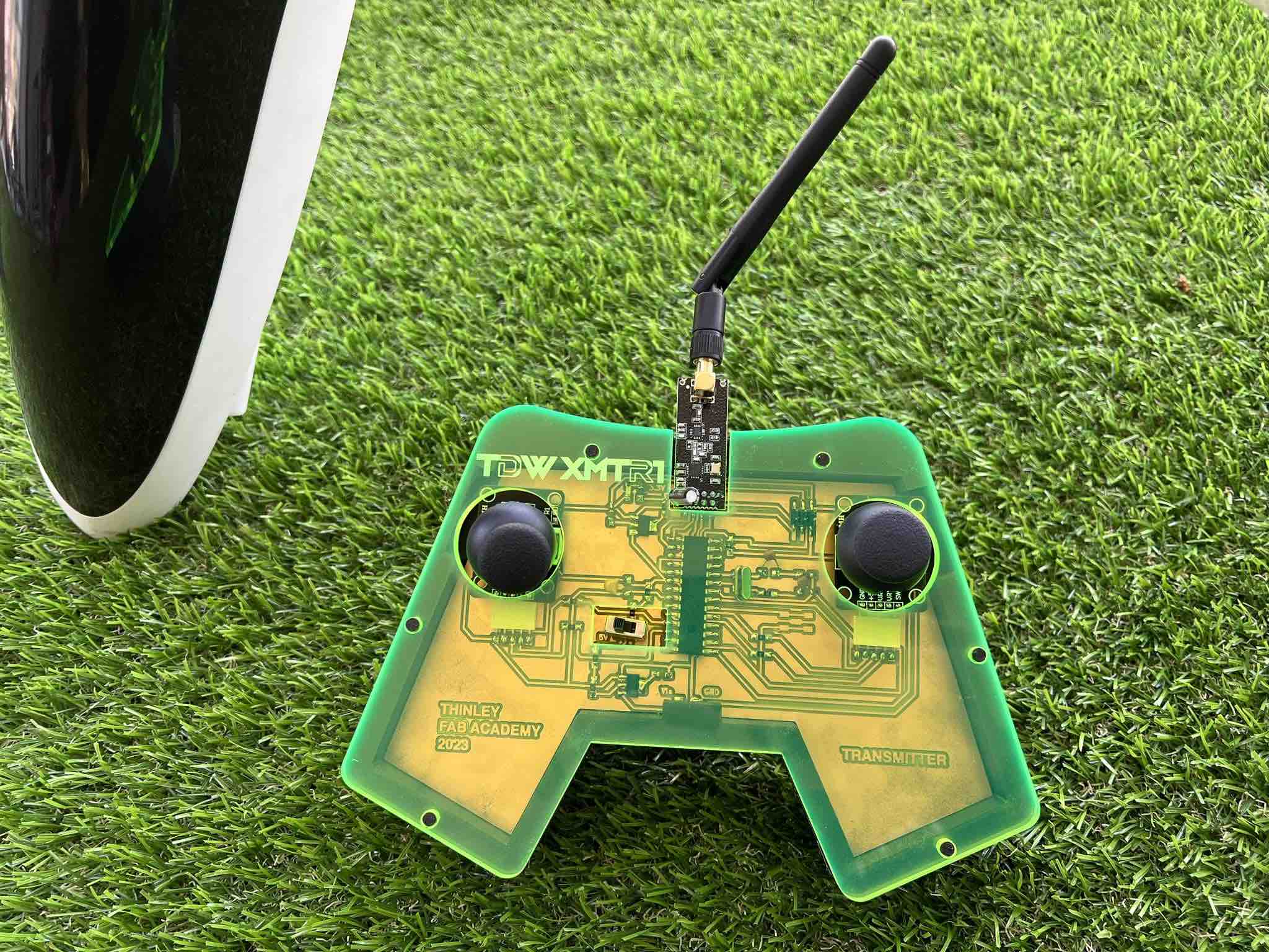
My custom board works!:
The communication between the RX and TW works as can be seen below:
For a more in depth look into my design, all my work and testing, please check out my The programming page under Final Project
3D Design and Manufacturing
All my 3D designing has been done in Fusion360. I will use the Prusa mk3 3D printer for my additive manufacturing and will use the Trotec speedy100 to laser cut acrylic for my subtractive manufacturing.
Transmitter Joystick
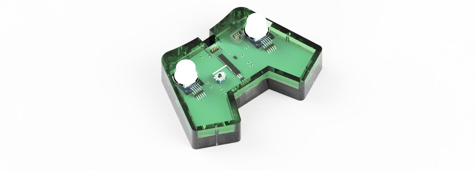
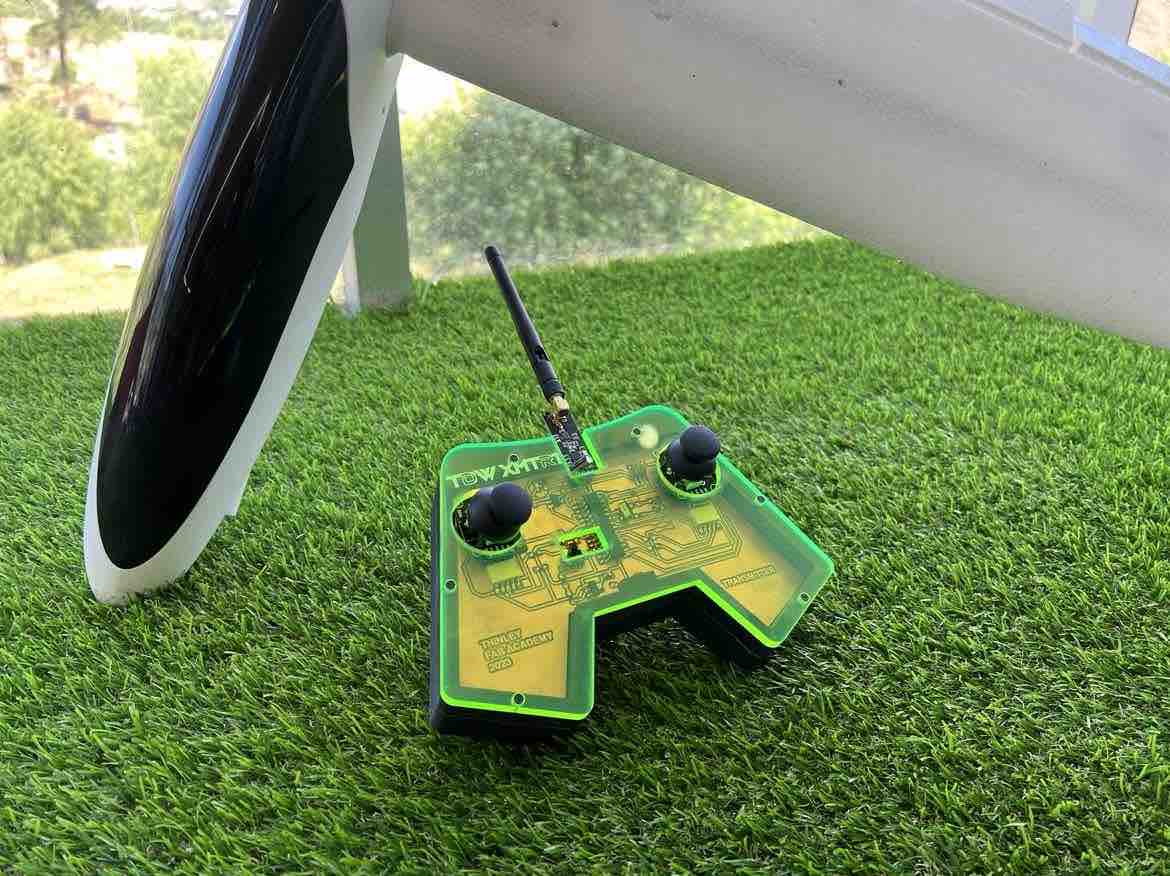
HERO RENDER:
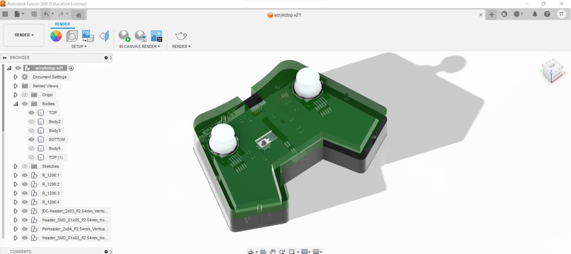
First, I exported my PCB as a step file from KICAD and then opened that up in Fusion360. This was done to give me a more detailed idea about the exact sizing of my transmitter. Then I also inserted the stls of the joystick that I found on grabCAD again for the same reason.
the Top:
the Bottom:
I went ahead and tweaked my pre-existing design to add said indents underneath the joystick case and then 3D printed it:
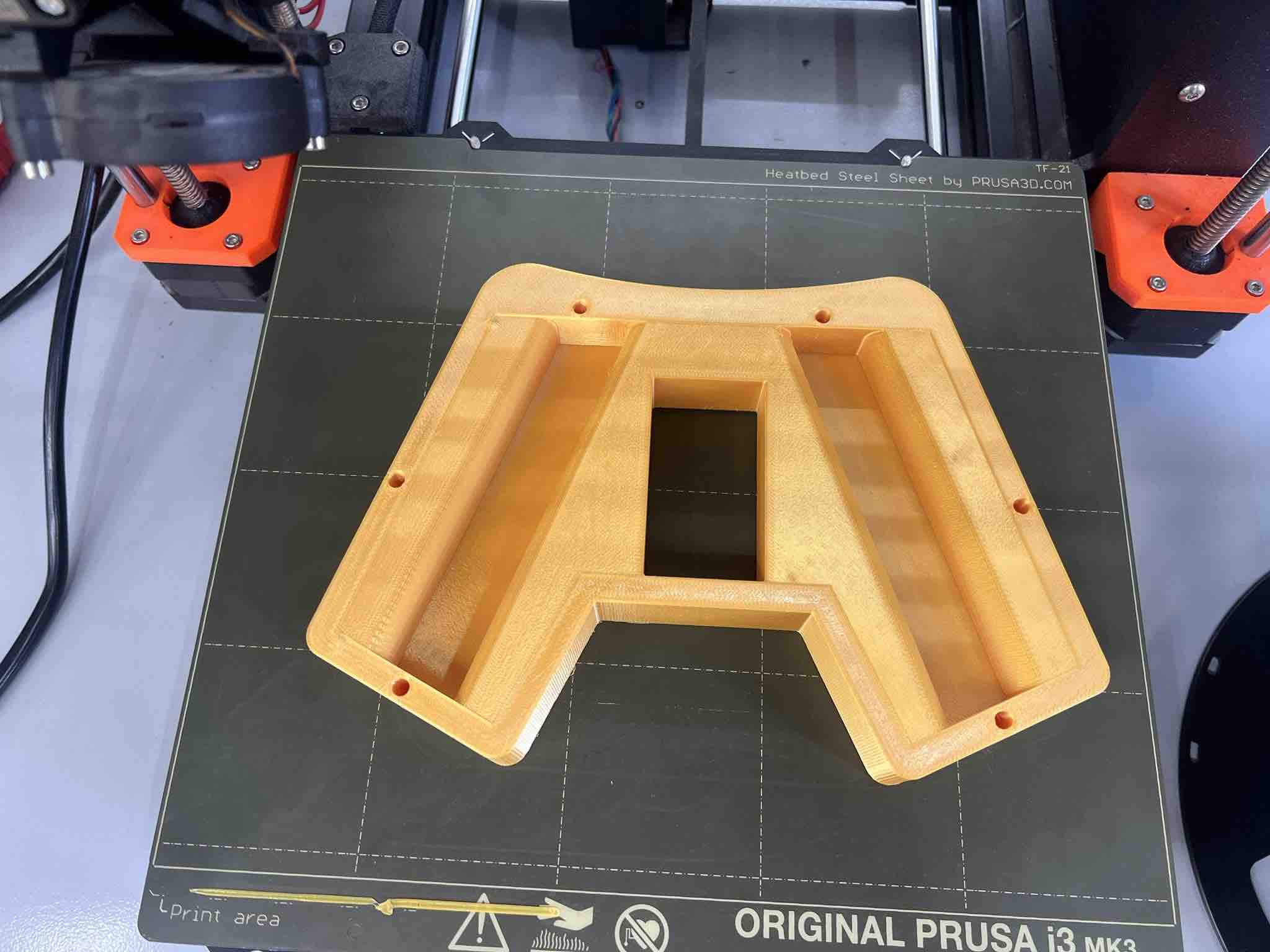
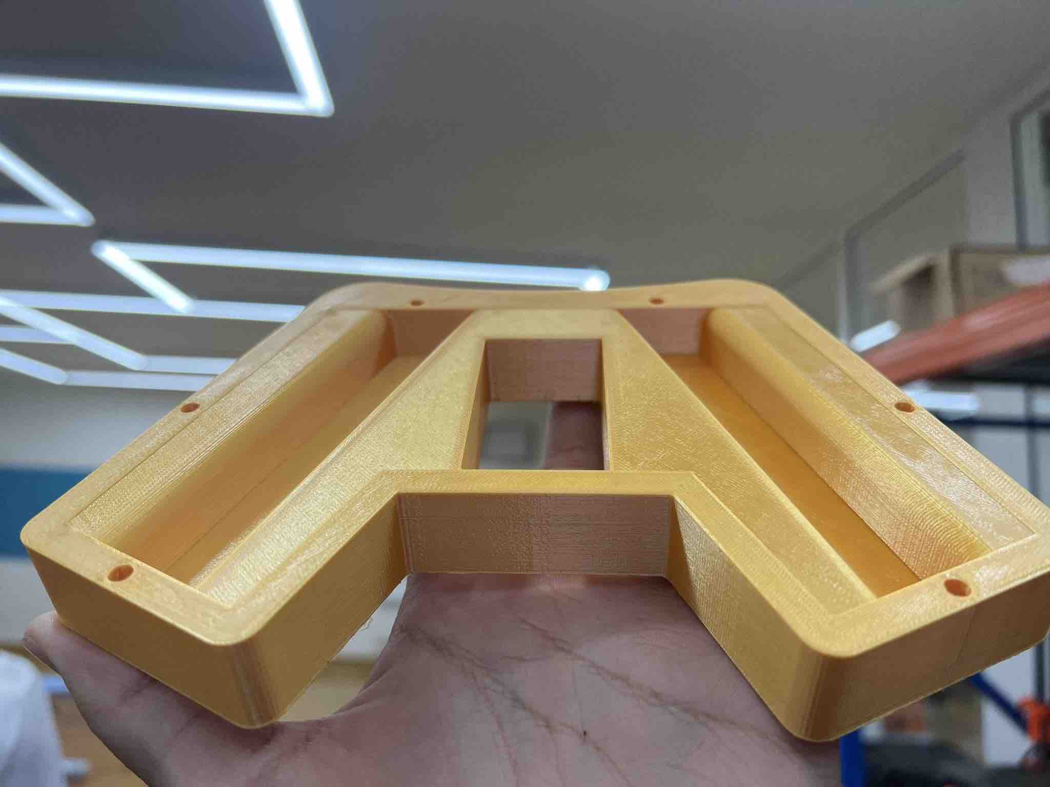
The design worked perfectly as I wanted!
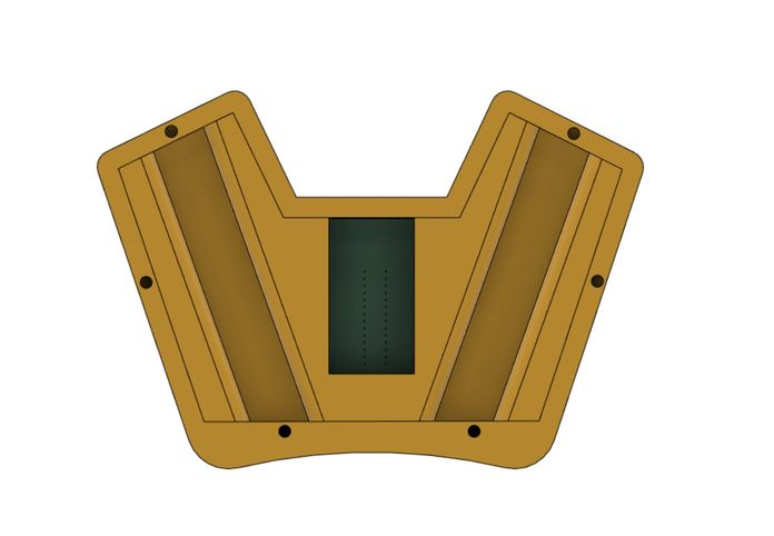
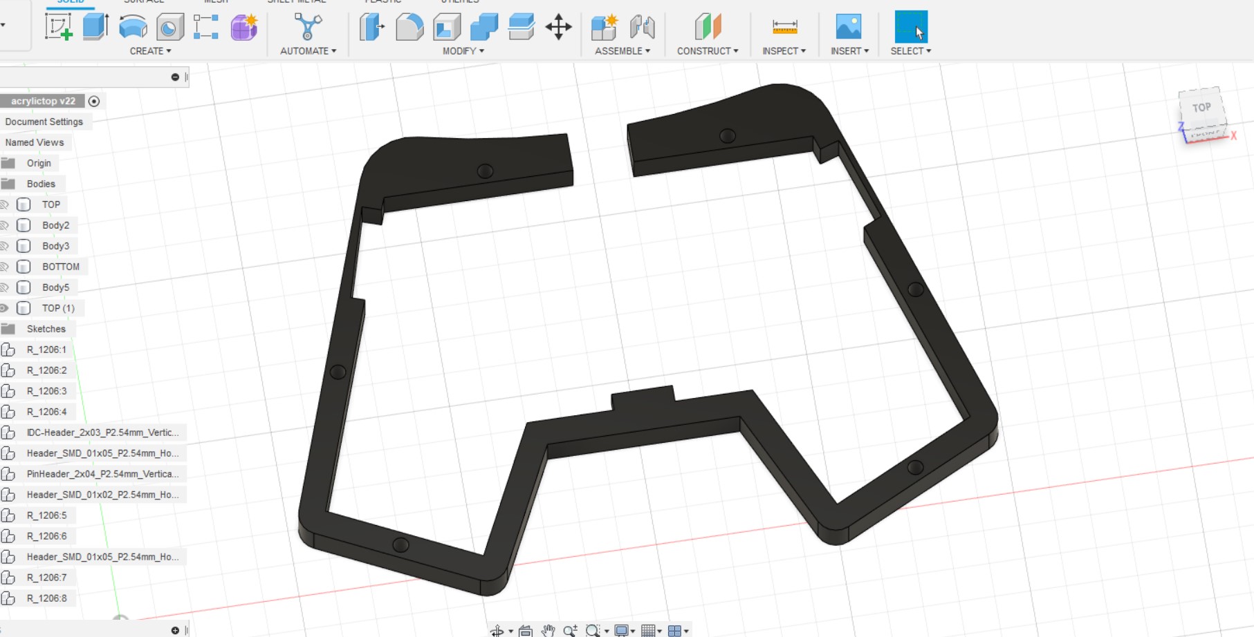
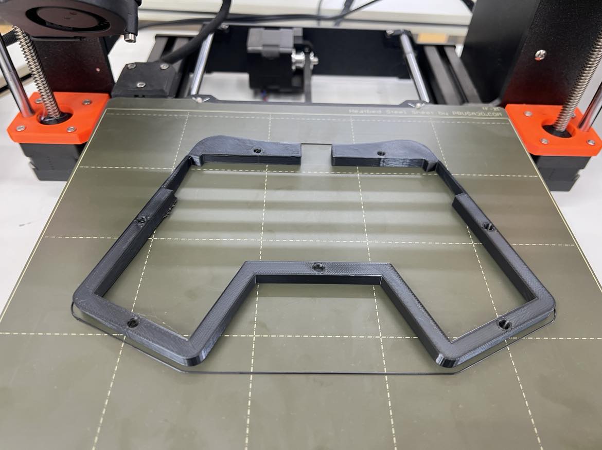
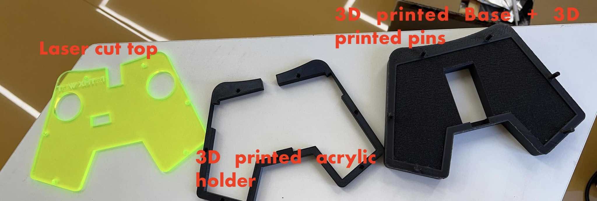
the Acrylic Frame holder:
To hold the acrylic on the top, I also designed the acrylic holder in Fusion and 3D printed it.
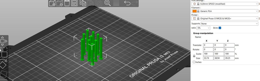
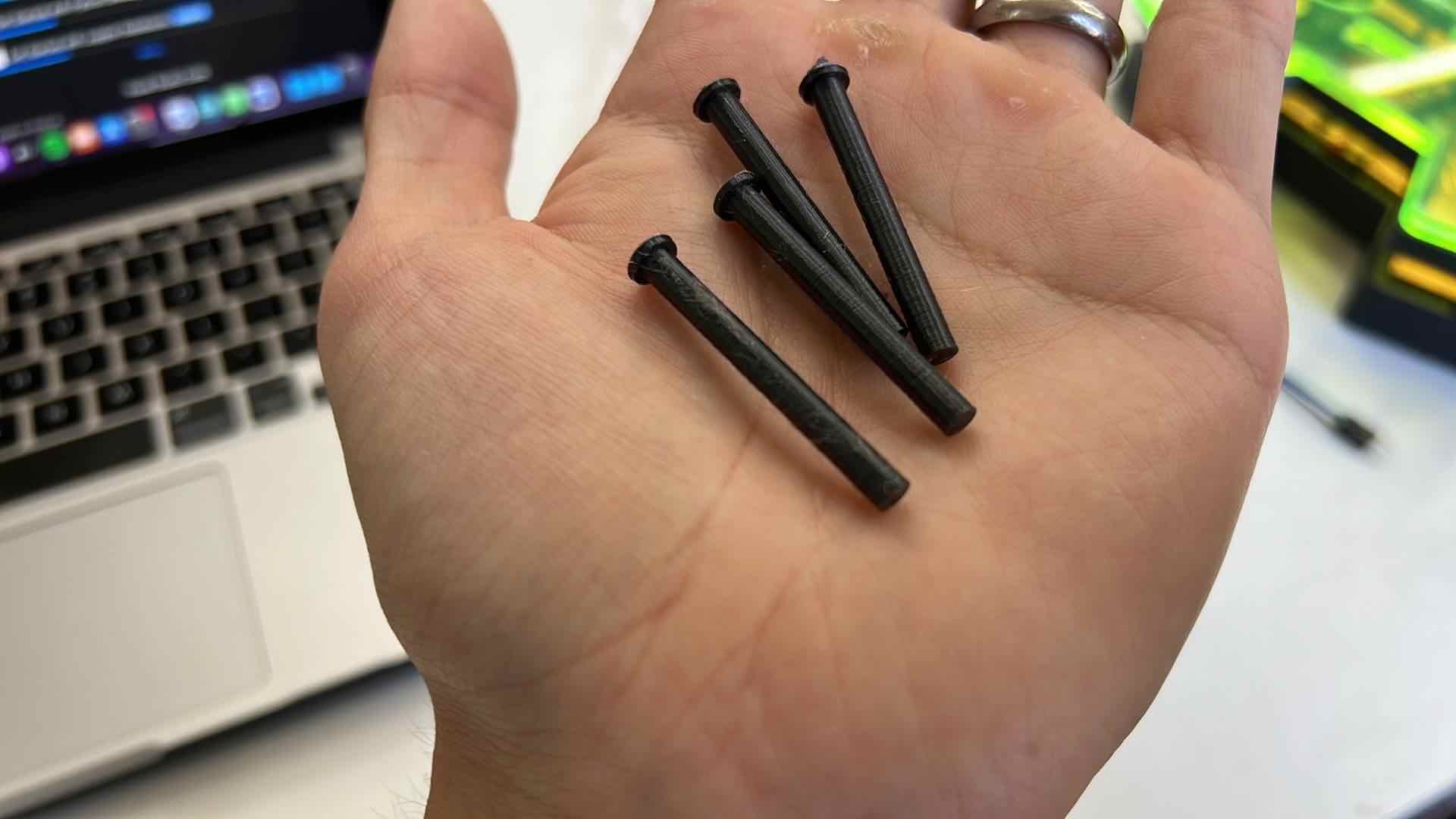
the Pins
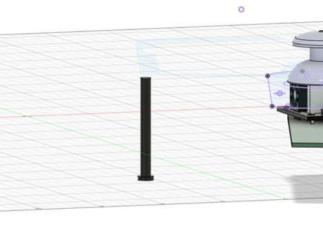
To hold the entire case together, I wanted to forgo using screws and wanted it to be completely 3D printed so I designed and printed the”3D printed Pins” to hold it all together.
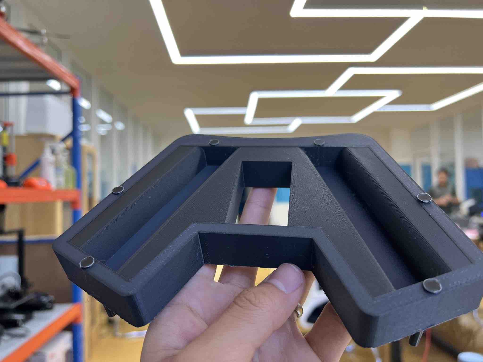
The bottom + the Pins:
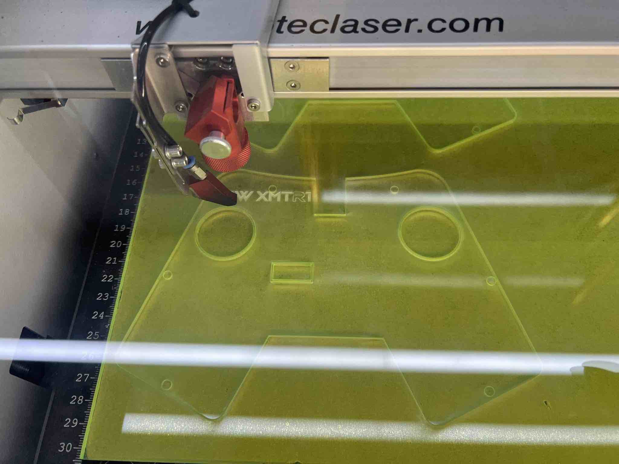
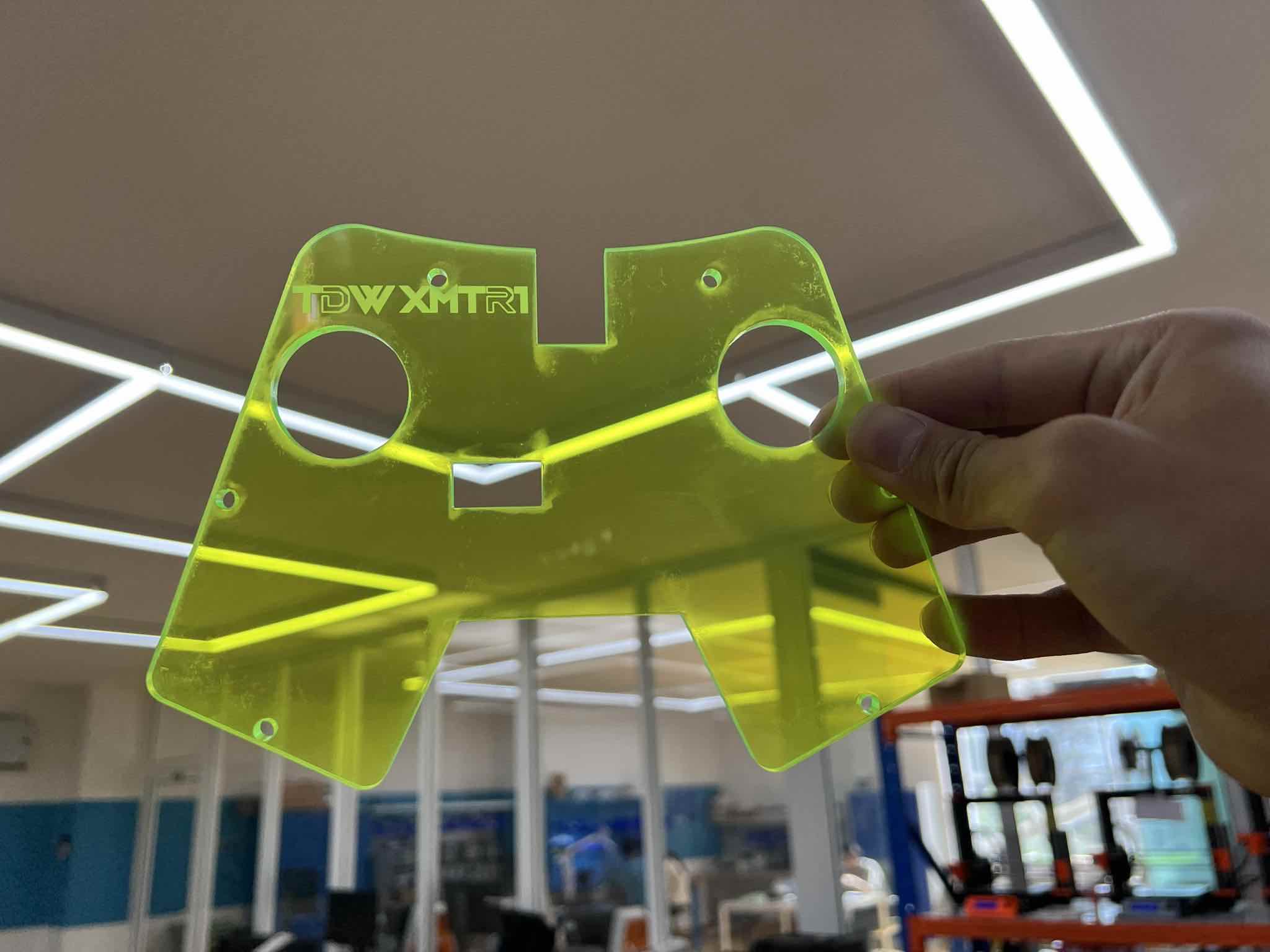
the Acrylic top:
I wanted to use clear neon acrylic for the top and hence printed the rest of my 3D printed parts in black color to make the green pop. I wanted it to be clear so one could see what my custom transmitter board looks like along with its components.
I created a new sketch in fusion360, and then projected the top of the joystick into the new sketch. Then I exported that sketch as a DXF and imported it into Inkscape.
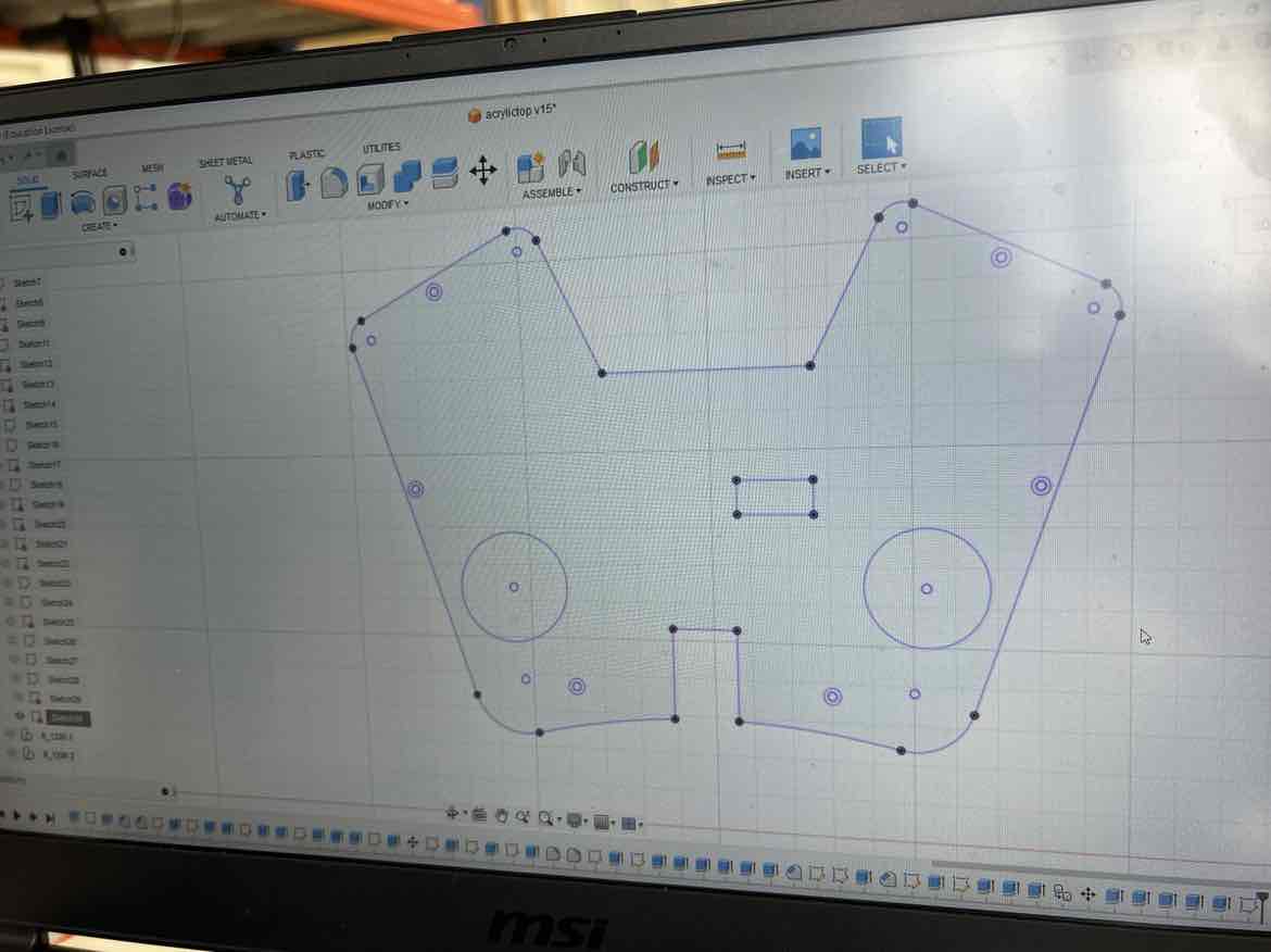
In inkscape, I set the lines I wanted to cut to Red (0.01mm) and the parts I wanted to engrave to black.
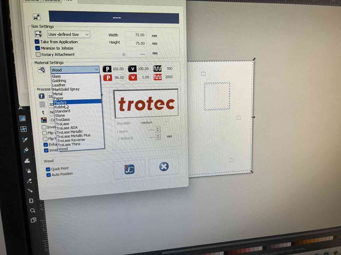
Then I hit, print to send it to the Trotec Job center where you define the power, velocity and origin of your job.
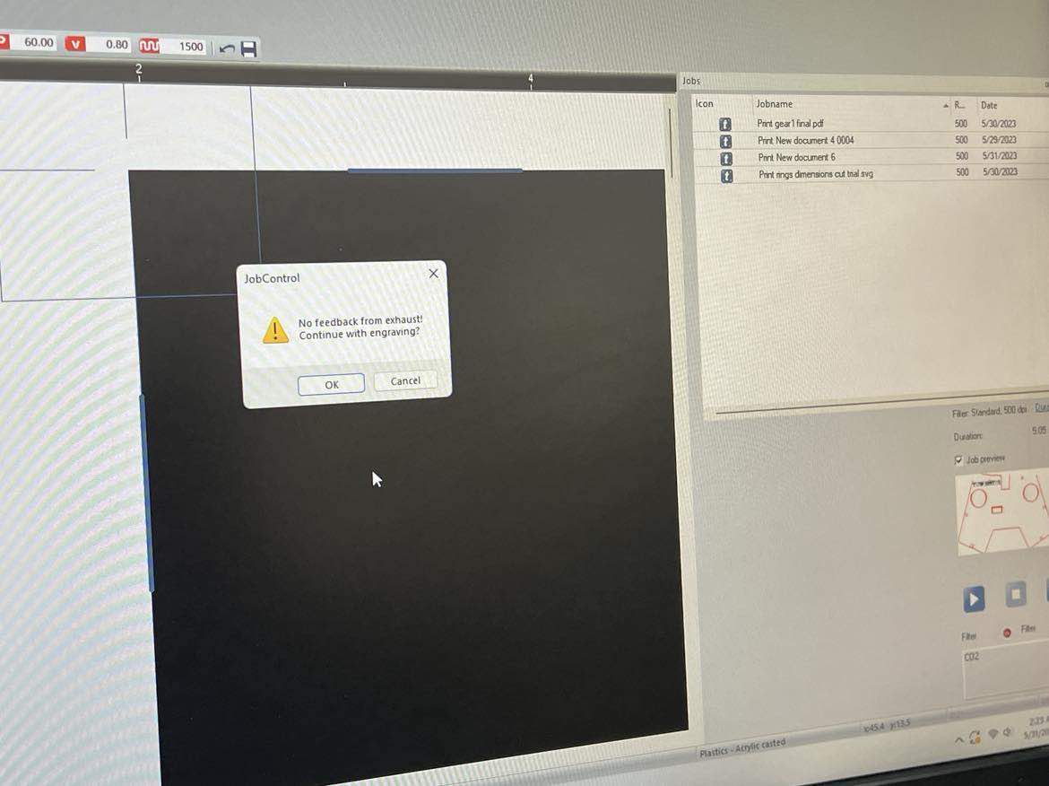
I started the machine, set the z axis and also my x and y positions.
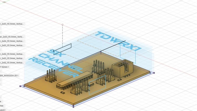
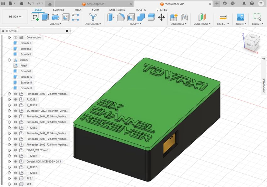
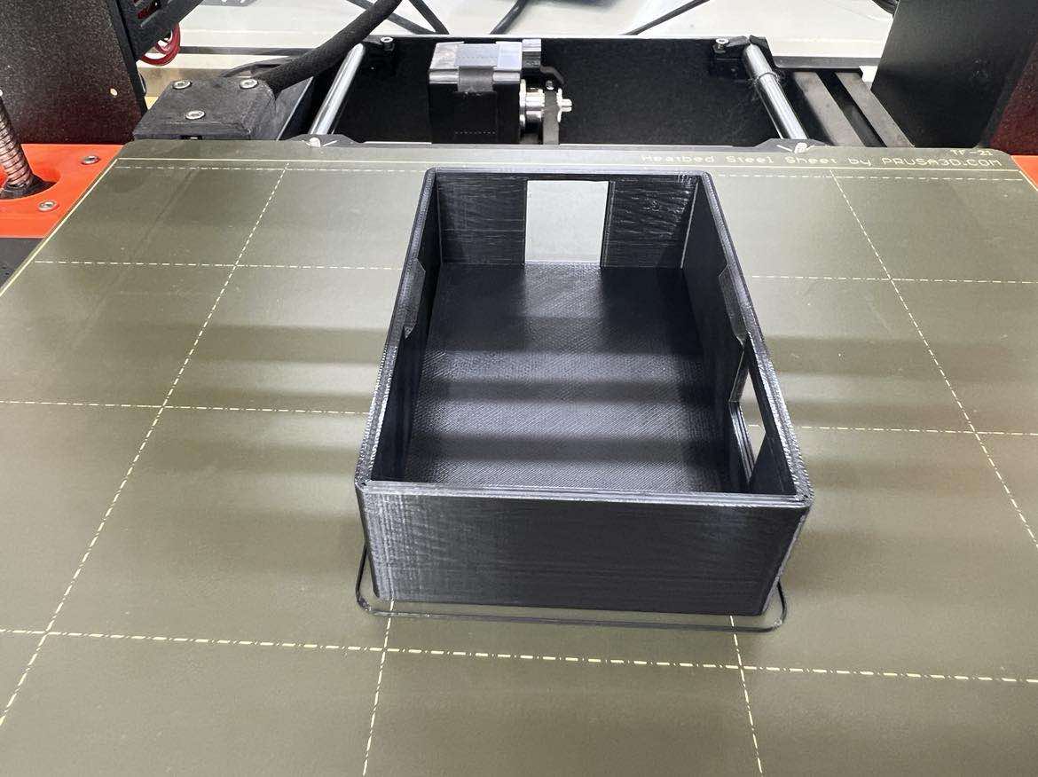
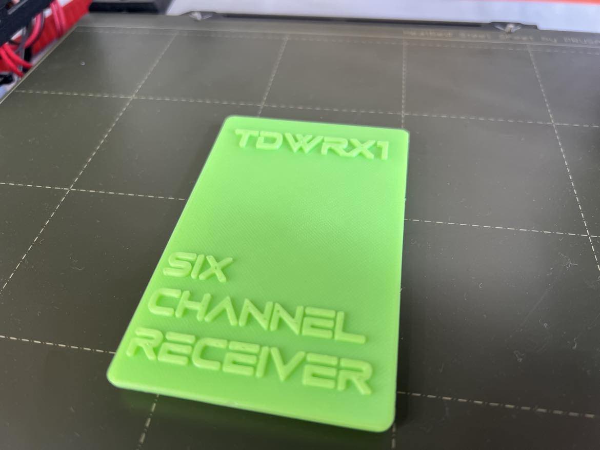
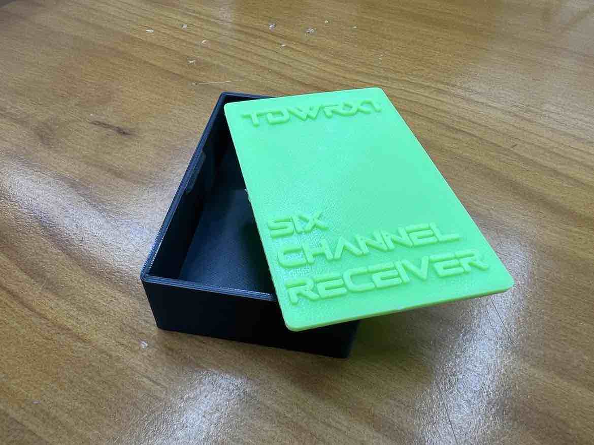
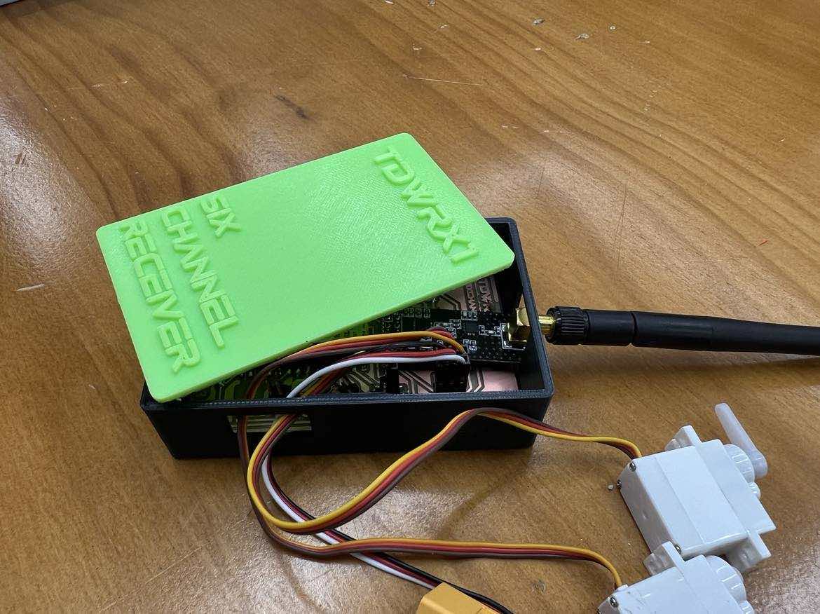
Receiver Case
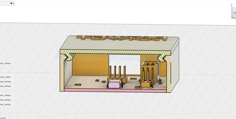
Next I wanted to make a housing case for my Receiver Board. I used Fusion360 to design it. First, I imported my kicad step file to get a better understanding of the dimensions of the board.
I wanted it to make it have a snapfit locking mechanism to eliminate the use of screws.
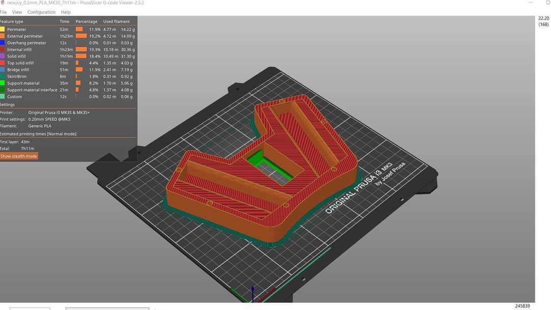
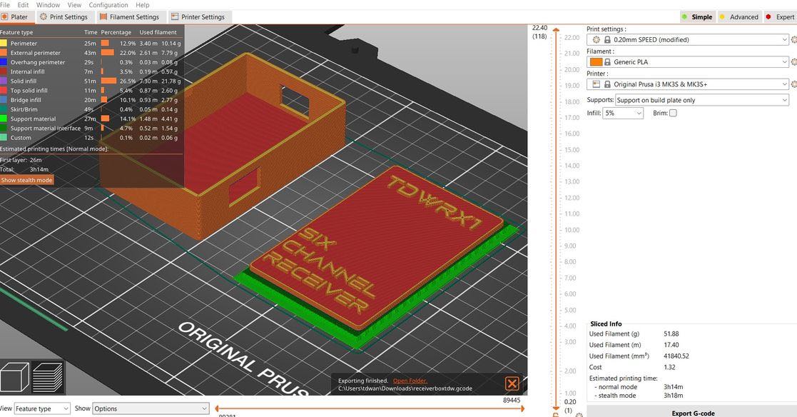
Then I used the Prusa slicer to slice the STL file.
For a more in depth look into my design & manufacturing, all my work and testing, the drone design, please check out my Design and Manufacturing page under Final Project
Assembly and Integration
Subtractive + Additive Manufacturing
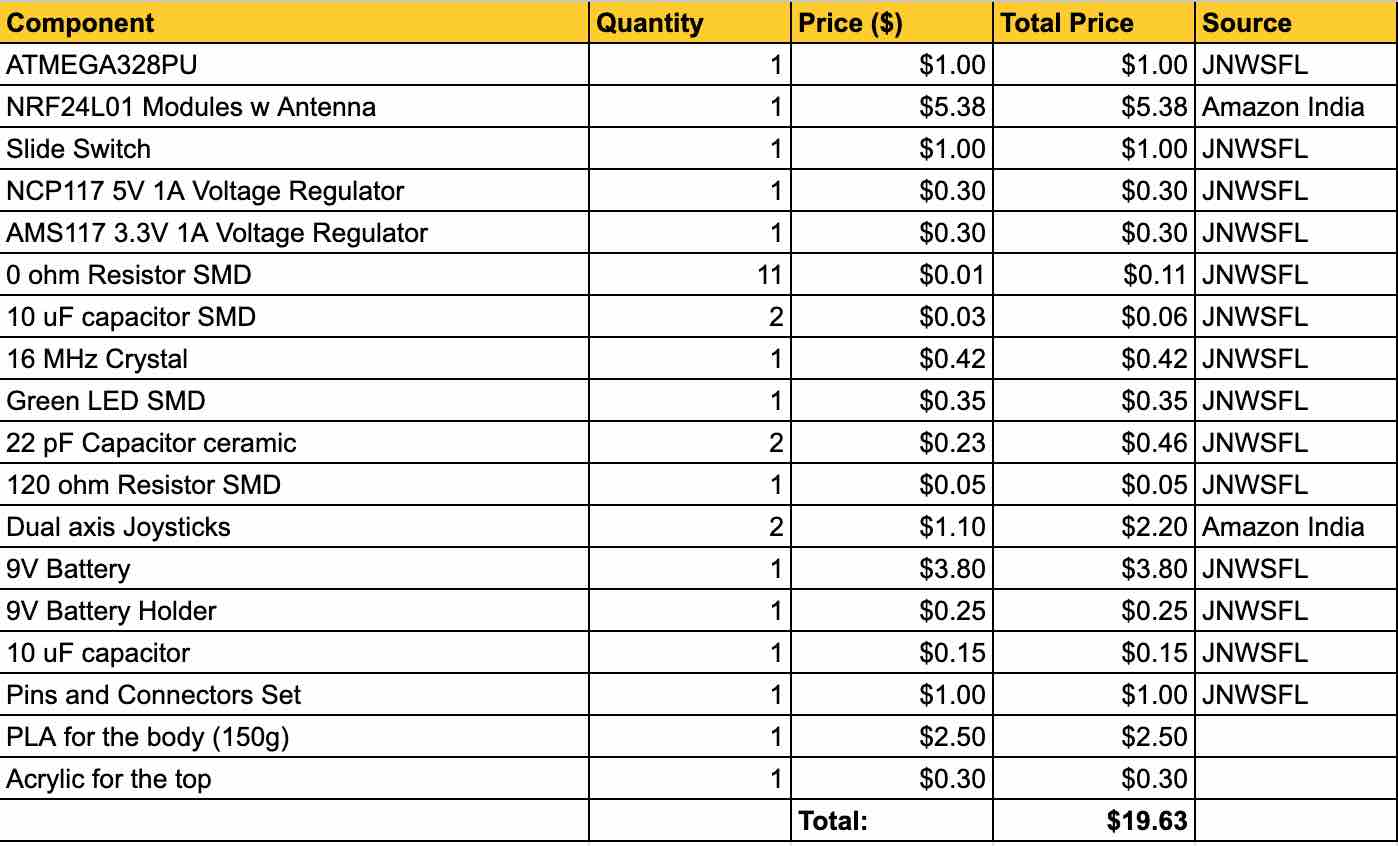
Bill of Materials
Transmitter
Receiver
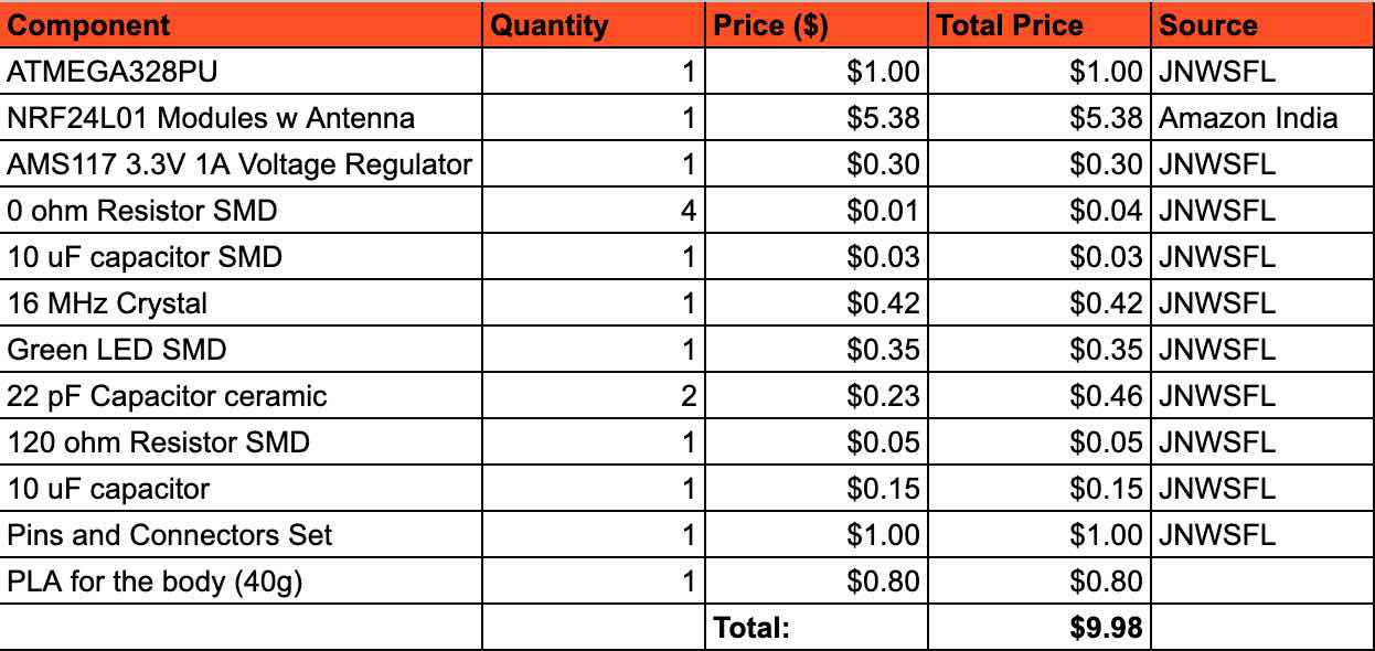
Total Cost: $29.61
Answers and Planning
Link to my website for the FAQs and planning
License
To get a better understanding of the licenses we can choose from I went to the Creative Common’s websites for Licenses, and read through the given options.
Of my options, I decided to go with the Attribution-NonCommercial-ShareAlike License.
Here is the License Deed and the Legal Code.
With this license, people are able to copy, redistribute whatever I did in any medium or format. They are also allowed to remix, transform and build upon what I did.
However, the material may not be used for commercial purposes or commercial gain. If the work is used, then credit must be given to me and any changes made to the work must be indicated.
The reason I went with this one is pretty straightforward. Since the drone industry is an ever growing market and technology, I don’t mind others using my work and ideas in a non-commercial setting for the greater good of the Drone (Transmitter/Receiver) Industry. My whole goal of making my own transmitter (and Receiver) was to make it fablab-able so sharing it non-commercially fits into my goals.
*For a more in depth look into the licensing and future scope, please check out my nvention, Intellectual Property and Income page *
Inspiration and What was done before me
KendinYap’s video on Youtube has made a custom transmitter and receiver but they used Arduino nanos and prototyping PCB boards. Same with MaxImagination’s Video.
My project worked on their blueprint, but I designed and produced the PCB (making it fablab-able) with the ATMEGA328PU being the microcontroller used.
Design Files
Arduino:
Acrylic Sketch:
Fusion360:
KiCAD: