11. Mechanical Design, Machine Design
This week we are working on building a machine with actuators and automation. The following are the assignments.
Group Assignment:
- Design a machine that includes mechanism+actuation+automation+application
- Build the mechanical parts and operate it manually The link to the Group Assignment is available HERE
Individual Assignment:
- Document the group project and your individual contribution
Starting Point
This year we have a total of Eleven students attending FabAcademy from Bhutan. We had divided ourself into two groups with the following members in my group.
- Kamal Kumar Chapagai
- Sonam Deki
- Tenzin Dorji
- Pema Yangzom
- Dorji Tshering Drugyel
- Thinlay Namgyal
- Sangay Penjor
With the group we discussed and decided to make something new. After numerous discussions we came up with the idea to replicate the design of SRM20 PCB milling machine. In my group we discussed as found the following to be the tasks at hand.
- Design of the Frame of the machine (Machine Design)
- Design of the control system of the Machine (Automation)
- Design of control system actuators (Mechanical Design)
In our group we have people with the following background
- Kamal Kumar Chapagai - Electronics
- Sonam Deki - IT and Programming
- Tenzin Dorji - Electronics
- Pema Yangzom - General for CAD Design and Cutting/Printing
- Dorji Tshering Drugyel - Generals for CAD Design and Cutting/Printing
- Thinlay Namgyal - Generals for CAD Design and Cutting/Printing
- Sangay Penjor - Architect for 3D Design and Cutting/Printing
Individual Task
With the job division as above, I begin looking for methods I can use to control and automate the PCB milling machine. First thing i started looking for is the hardwares required to make a successful milling machine. After number of studies we came up with the following requirements.
- Motors for Milling and Axes
- Controller board
- Motor controller
- Controller Software and drivers.
After numerous online search we came up with two motor types, One Arduino Mega board as controller and Arduino Mega Motor shield and motor driver for driving the motor. Further we also found out that there are a couple of opensource software and systems we can make use of to computer control these motors precisely.
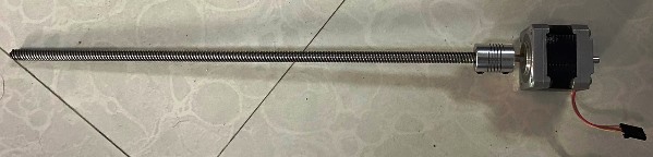
Finding the components and their specifications: For the control of XYZ axis movement of the machine, we can make use of three stepper motors. The specifications of the motors are as follows: Stepper Motors STP-42D201-37:
- Operating Voltage: 12Volts
- Peak Current : 1.7A / Phase (Two Phase exciting)
- Mass : 0.27kg
- Position Accuracy: 1.8degree per with error range of 5% in full step
- Holding torque: 0.314N-m (3.2kgf-cm) minimum
- Maximum Starting Pulse Rate: 1600pps min, Half-step No-Load
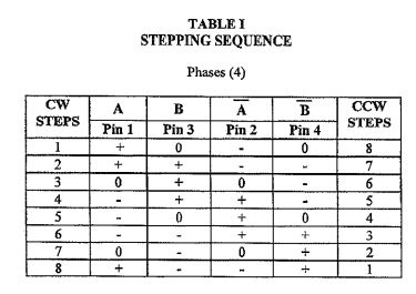
Torque Speed Characteristics The torque-speed characteristics of the motor and its stepping sequencing is shown below:
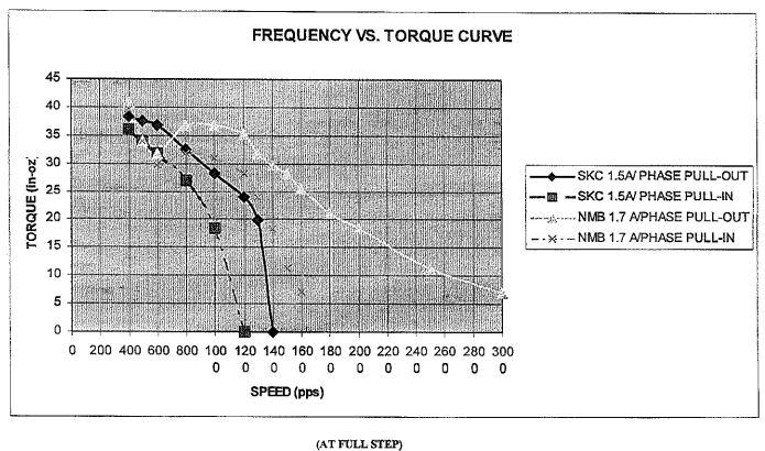
Since the load of the motor is mainly due to the bed and friction due to the sliding part, the maximum required torque would be sufficient for the application. Further, we also have to conside the requirement of currents. The power supply we are making use of is external with a voltage of 12V and current rating upto 5A. This would be sufficient to run the motors sufficiently.
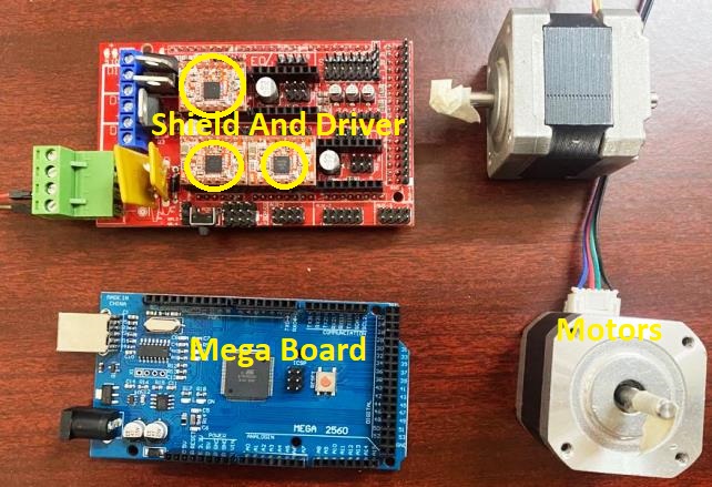
Controller Board and Driver
For the current work, we did a little research to determine the suitable board and motor drivers that we can make use of. Another consideration we had to make is the availability of these components in our lab. Looking around we found that we can make use of Arduino Mega board with Mega Shield connected to motor driver modules. Therefore we proceeded with the above components for controlling the motors.
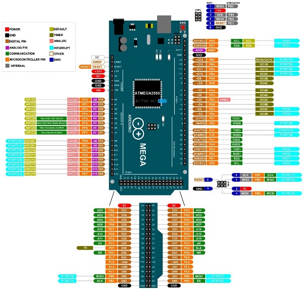
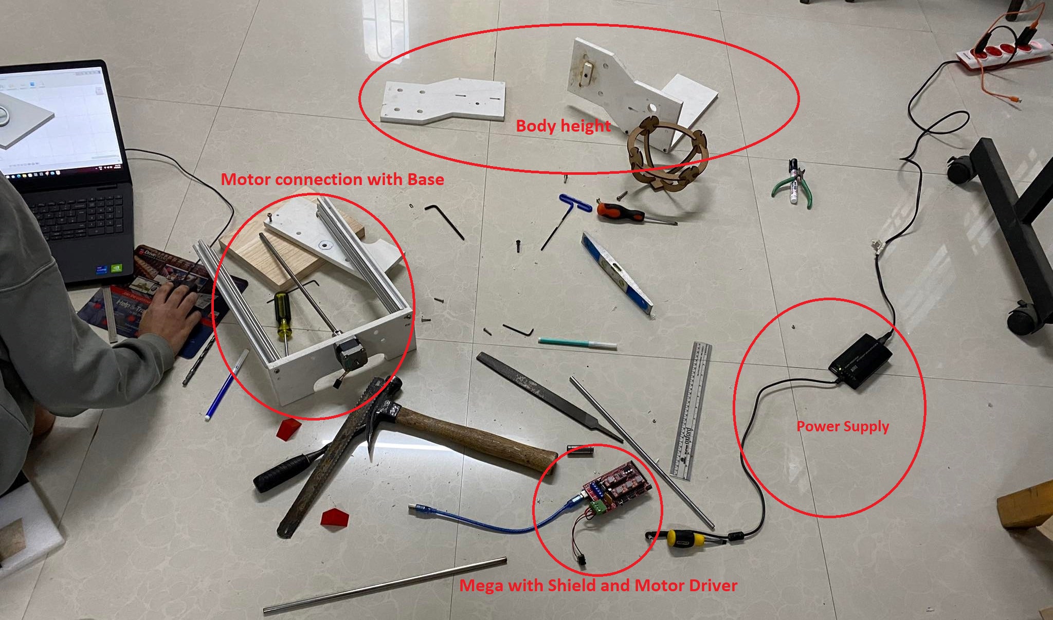
The Arduino Mega board along with its shield and driver connection is shown below:
Motor Drive A4988
For the motor driving, we are making use of motor driver module with driver A4988. The schematic of the driver is shown below.
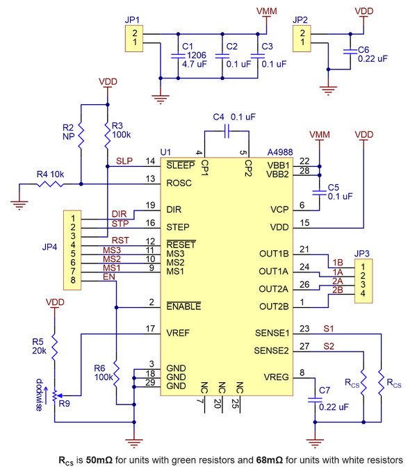
The diver module has the capability of controlling the stepper motor with a maximum current of 2A with additional heat sink requirement while a nominal current of 1A can be suppied without overheating.
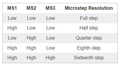
Steps
Step (and microstep) size Stepper motors typically have a step size specification (e.g. 1.8° or 200 steps per revolution), which applies to full steps. A microstepping driver such as the A4988 allows higher resolutions by allowing intermediate step locations, which are achieved by energizing the coils with intermediate current levels. For instance, driving a motor in quarter-step mode will give the 200-step-per-revolution motor 800 microsteps per revolution by using four different current levels.
The resolution (step size) selector inputs (MS1, MS2, and MS3) enable selection from the five step resolutions according to the table below. MS1 and MS3 have internal 100kΩ pull-down resistors and MS2 has an internal 50kΩ pull-down resistor, so leaving these three microstep selection pins disconnected results in full-step mode. For the microstep modes to function correctly, the current limit must be set low enough (see below) so that current limiting gets engaged. Otherwise, the intermediate current levels will not be correctly maintained, and the motor will skip microsteps.
Control Inputs
Each pulse to the STEP input corresponds to one microstep of the stepper motor in the direction selected by the DIR pin. Note that the STEP and DIR pins are not pulled to any particular voltage internally, so you should not leave either of these pins floating in your application. If you just want rotation in a single direction, you can tie DIR directly to VCC or GND. The chip has three different inputs for controlling its many power states: RST, SLP, and EN. For details about these power states, see the datasheet. Please note that the RST pin is floating; if you are not using the pin, you can connect it to the adjacent SLP pin on the PCB to bring it high and enable the board (Source: Datasheet).
The basic connection diagram is shown below:
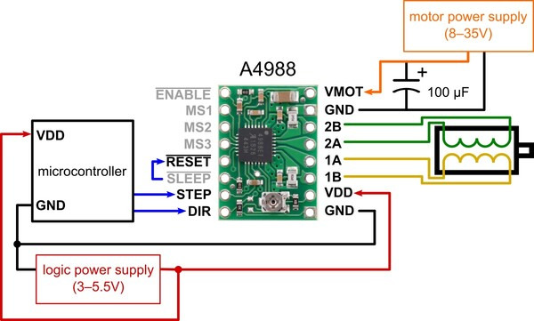 We made use of the above connection diagram to understand the connection of the driver board to the arduino shield and inturn to the arduino mega board.
With the components identified for the three axis control, we proceed to programming the board and testing the functionality of the board with the Motor and Driver.
Mega Board Programming and Testing
For the programming of the board, we have made use of two opensource softwares namely the MARLIN framework and grbl framework with grbl controller to control the board and automate the system.
MARLIN Firmware
First created in 2011 for RepRap and Ultimaker by Erik van der Zalm et. al., today Marlin drives most of the world’s 3D printers. Reliable and precise, Marlin delivers outstanding print quality while keeping you in full control of the process. As an Open Source project hosted on Github, Marlin is owned and maintained by the maker community (Source:https://marlinfw.org/).
The marlin firmware can be used to automate 3D printers and other machines. For our work, we tried to work first with MARLIN firmware in grbl controller to check the functionality of the output devices.
Downloading and Installing the MARLIN Firmware
In order to use the MARLIN, I make use of the tutorial available HERE. First up, I download the latest version of the MARLIN firmware from https://github.com/firepick-delta/Marlin. WIth the file downloaded to the local drive. I move on to adding the file as library to the Arduino. I manually unzip the folder to my arduino library folder and open the Marlin.ino.
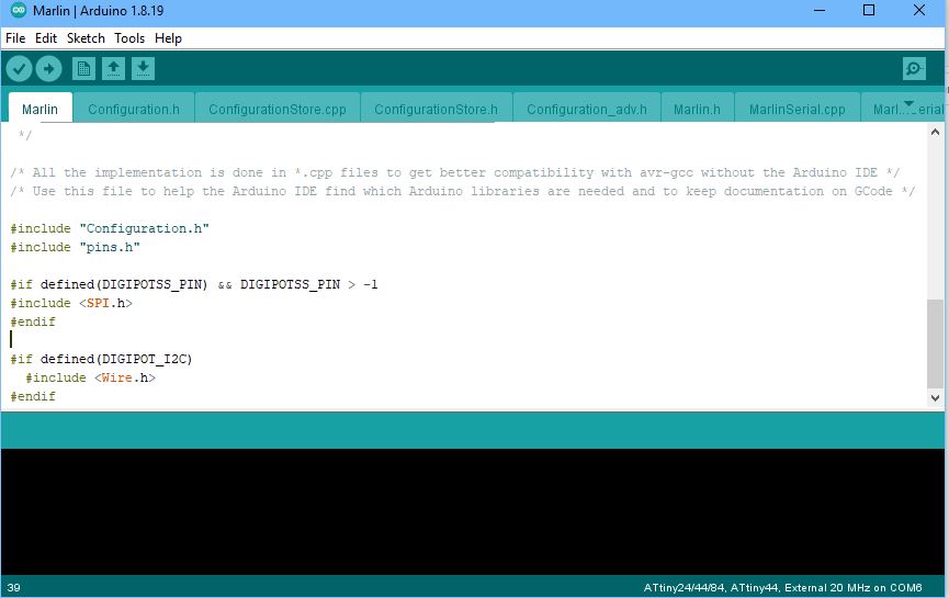
With the marlin firmware downloaded and installed for Arduino, we burn the codes to the Arduino Mega Board. However, during program loading we kept getting a number of errors one of which was the code size. The size of the MARLIN firmware was larger than the memory of the Atmega board. After searching around we found that we could remove some of the codes that we would not require to use and decrease the size of the firmware to fit to the board. However, it was becoming more tedious to get to all the functions and files and try to segregate the files that we wouldnot require. Therefore, we paused the work with MARLIN firmware and moved on to working with the grbl firmware.
GRBL Firmware
GRBL (pronounced “gerbil”) is free and open-source firmware that controls the movement of CNC machines and can run on any boards that have an ATmega328-based microcontroller. The firmware was written in 2009 by Simen Svale Skogsrud, and since then, it’s been continuously maintained and updated by the open-source community. On GitHub, the repository is currently maintained by Sonny Jeon (Source: https://all3dp.com/). GRBL uses gcode as input and outputs signals via the arduino pins to connect to the machine in use. We make use of the GRBL firmware after downloading and make use of GRBL controller to send the G-code to the machine.
With the GRBL firmware, we can change the desired header and configuration file to make use in our settings and use. The steps to download and install GRBL firmware to arduino is as follows:
- Download the latest grbl sourcecode as .zip
- Download and install Arduino IDE if not previously installed.
- Open the grbl .zip and navigate to a folder simply called “grbl”
- Extract the folder to a known place and open the arduino ide
- In the arduino ide, navigate to sketch>include library> add .ZIP library, Alternatively the file can also be directly copied to the arduino library folder.
- Navigate to the grbl folder and click ok.
The download link to the GRBL firmware page is: https://github.com/gnea/grbl/releases. There are a number of varients of the GRBL firmware for different arduino boards. For our case, we have found the specific firmware for the Arduino Mega board from https://github.com/gnea/grbl-Mega.
With the file downloaded and installed on to the library of Arduino, we will get the example file on the arduino IDE.
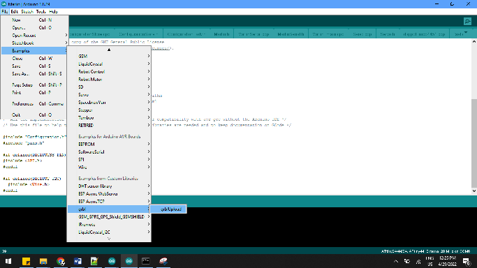
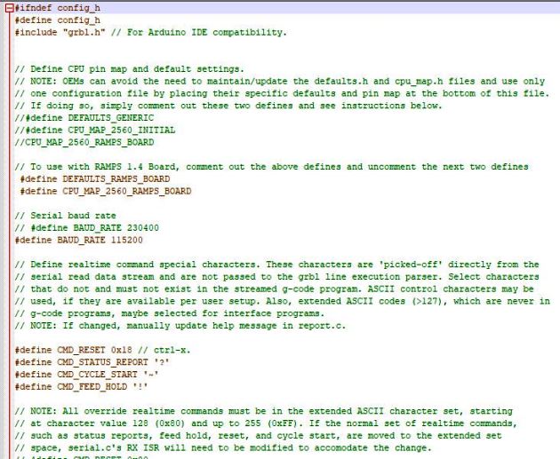
The GRBL upload sketch contains only the heade file but all the required files are within the library folder. There are a number of customization present in the firmware and requires for us to make changes depending on our need. The first customization is to change the configuration file to the board that we make use of. For our case, the board we are using is the Mega board with the RAMPS (RepRap Arduino Mega Pololu Shield). So we change the configuration file to first change the board to our board so that the pin configuration of the firware and the pin of the shield matches. This can be found in config.h file:
The cpu_map_atmega2560.h file also contains the pin map of the board we make use of. We compare the pin configuration in the file with the pin configuration file in the figure below.
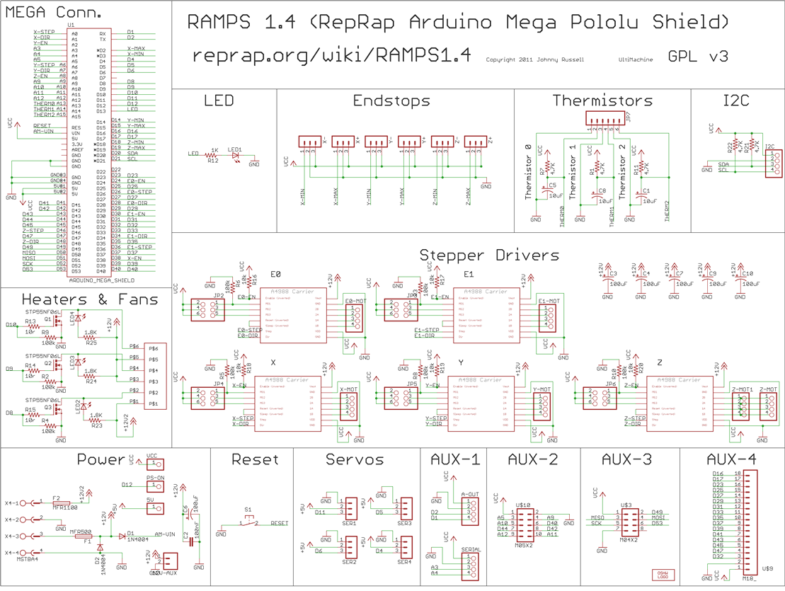
The details of the connection diagram and pin configuration examples can also be found at http://domoticx.com/arduino-mega-shield-ramps/. With the configuration files properly edited we make the circuit connection of the Mega board to the Shield and further connect the motor driver and the motors refering to the figure below:
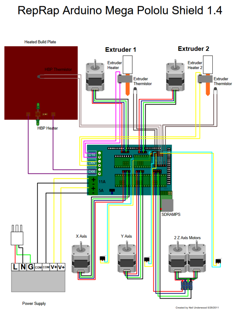
The above image is for a 3D printing application, therefore for our case we use only three motors for XYZ direction motors.

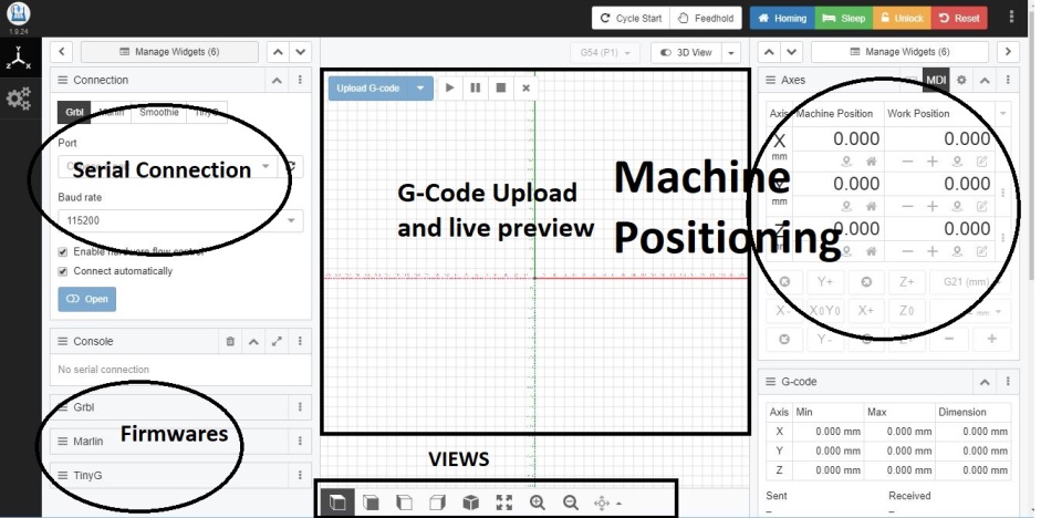
Then we upload the GRBL code to the MegaBoard. With the code uploaded, we make use of the CNCJS software to control the movement of the motors. The CNCjs software can be downloaded from: https://cnc.js.org/docs/desktop-app/. With the file downloaded, we install the software in our PC and open it.

The CNCjs has a couple of interesting thing: - It can be used with a couple of firmwares including GRBL, MARLIN and TinyG - It uses serial communication with the controller and can also be used to send control codes. - The G-Code can be visuallized with the live toolpath preview - We can also control the machine position manually and set the home positions. - The step size can be changed on the controlling software to change the number of rotation of the motor.
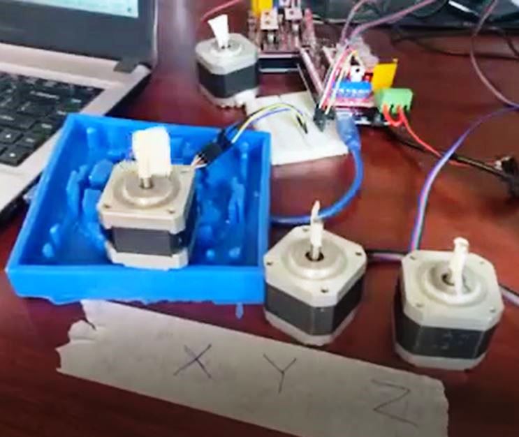
With the GRBL code installed on MEGA board and CNCjs connected to the serial port to the board, we check the functionalities of the XYZ axis motors. The working of the motors is shown in the video below:
With the motors running we move on to assembling the components on the chassis of the machine. Initially, we had the machine designed and the chassis of the machine ready for assembling. The materials of the machine are as follows:
- PVC board frame for chassis with alumunium bracket
Design dimensions:
-
Body Frame : 26cm x 34cm (Material Thickness = 6mm)
-
Base Height : 10cm
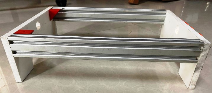
- Body Height: 28cm
- Base Plate: 17cmx22cm (Movement with V-bearing and threaded rod)
- Z-Axis maximum height from base: 15cm
- Effective base dimension: 13x13cm (Initial Design 15x15cm but due to edges where the motor is connected the effective dimension decreased)
- XYZ movement mechanism: Slot bearing support with V-slot movement control
For the frame of the machine, we made use of CNC machine, Table saw and band saw machine to cut the parts and drill required slots. Further, we used 3D printing to print the wire cable and few slot sealing to prevent rods from rolling during movement. The video below shows few clips compiled from working with the CNC and table saw to make the parts.
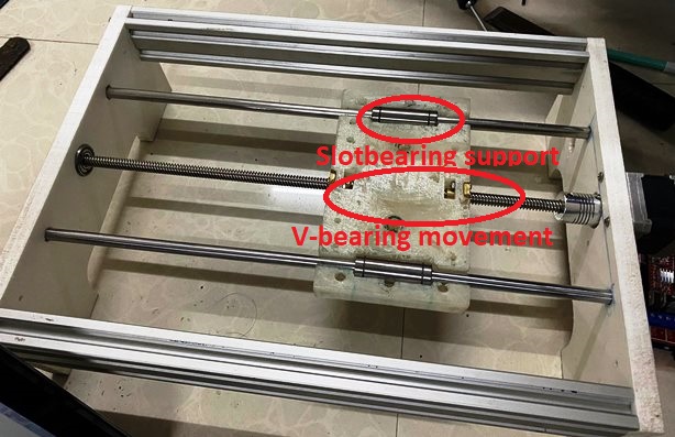
With the components identified and individually fabricated we move on to assemble the components together. We first fix the motors (12V Stepper Motor with threaded rod) onto the base part and the body using slot bearings to support. The moving parts are supported with slot bearing to give least frictional resistance while we make use of v-bearing to connect the moving parts and the motor with threaded rod. The process of assembling the parts are shown below:
Assembling the Parts
For the assembly of the parts, we first connect the motors to the base and motors to the frame sepatately. Further we assemble the parts frame of the machine together. We screw the parts together to get the body installed.
Then we fix the controller board to the frame and make connections to the motors.
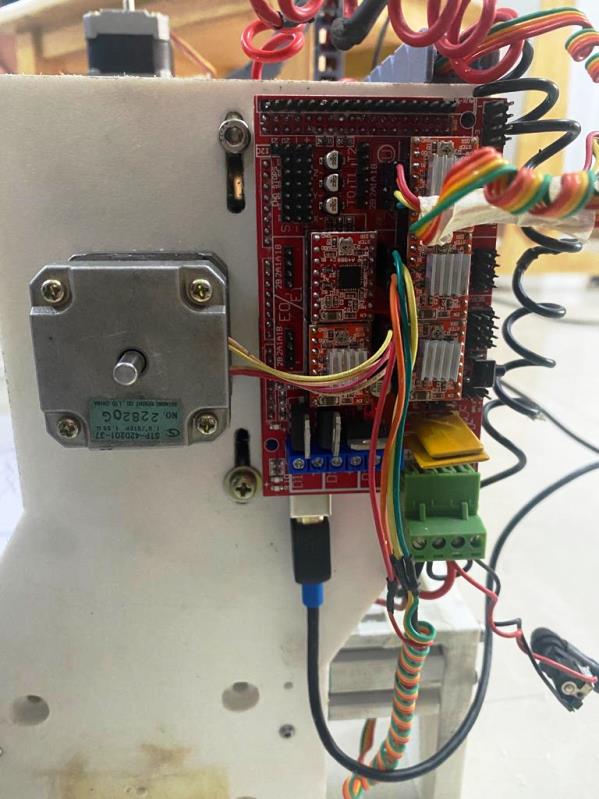
We made use of power supply adapter available in lab to power the board. The supply has variable power supply with range of voltage and current carrying capability upto 5A. With the parts assebmled, we proceed to connecting the controller board to the PC and check the runout of the machine. During the runout test of the machine, we found that there was alignment issue of the base plate due to small difference. We did minor filing of the slots and retested the alignment.
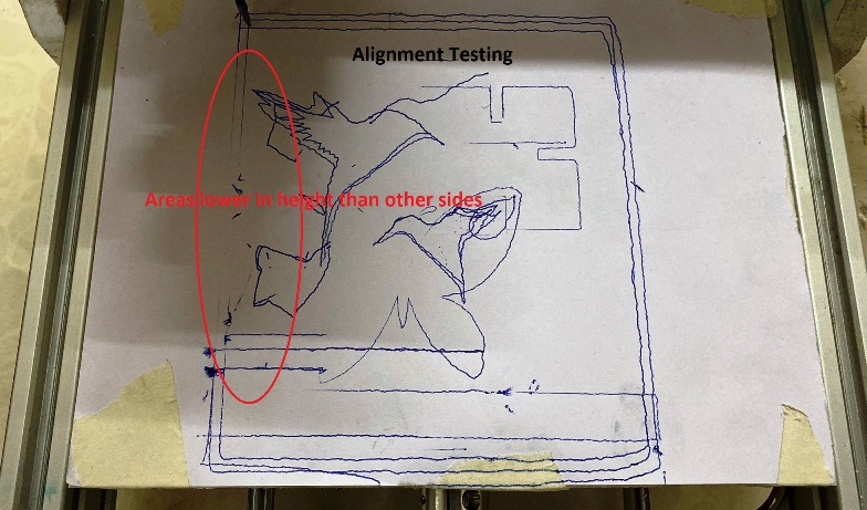
The left part of the base was not aligned with the right side as shown in the image above, after few alignments we were able to properly align the base of the machine.
Then we proceed to creating G-code and send it to the machine for automatiing the machine. To generate the G-code, we make use to two methods. The first method was to to create design using Fusion360 and make use of manufacture tool in fusion360. Initially we created small design and generate the g-code. The method used for the same can be found HERE
The other method I made use of is to generate G-code from vector file in inkscape. In inkscape, we can use PNG file and use vector to g-code tool to generate the g-code. For the same, we make use of inkscape to first vectorize the png file.
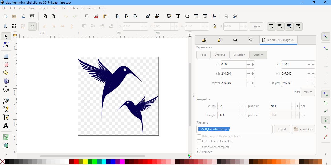
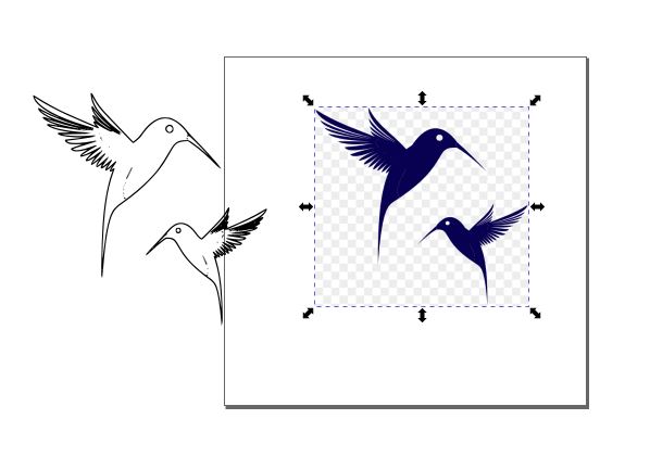
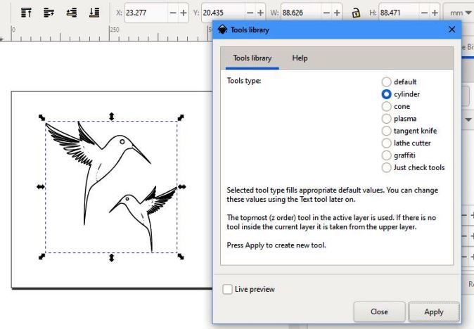
With the image vectorize, we make use of image to G-code tool to create the g-code. In the tool, we have to define the tool in use and also define z-parameters. For the current work, we are not milling but drawing, therefore we keep the z-value to zero or a small negative value so that the pen is able to write successfully. We can also change the jog-height and the dimension of print.

The third method we made use of to convert the file to g-code was DXF to G-Code Converter. The design file for this case is drawn using Fusion360. using the fusion360, we first make the desired design and export to dxf file. The dxf file can then be converted to g-code using the above software.
With the G-code for the desired design generated, we move on to connecting the machine to the CNCjs software and load the G-code. We can move the machine to desired position using the onscreen movement control on CNCjs. Then we make the XYZ axis to zero. That is going to be the origin position of the machine to start working from.
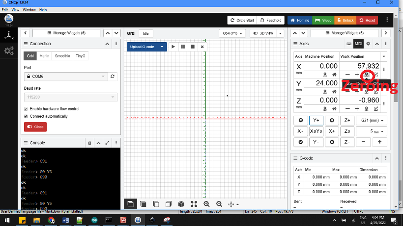
With the zeroing done, we load the G-code to the CNCjs software and give it to the machine.

The final outcome of the printing process is shown below:
The work progress for the entire week is shown in the video below: