20. Group Assignment Week 3 - Computer Controlled Cutting
This week we had a group assignment to work on laser cutter and individual assignment to work on vinyl cutter and laser cutter. The folowing was the group assignment:
Group Assignment:
- Characterize your lasercutter’s focus, power, speed, rate, kerf, joint clearance and types
Group Members
Vinyl Cutter
Vinyl Cutter Details
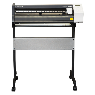
The vinyl cutter at our lab is the Roland CAMM-1 GS-24.

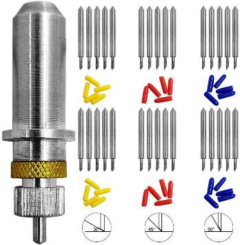
It came with 3 type of cutting blades, each with differnt angle as shown below.
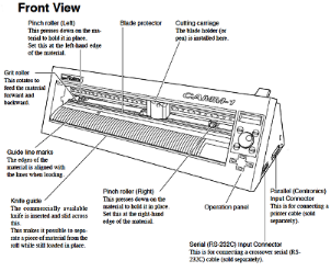
Starting and Working with Vinyl Cutter
- First the vinyl cutter was started on. The cutting carriage goes to its home point at the Right Hand Side. Once started, we set the origin to the point of interest (Press Origin for 3 Second). There are three markers on the vinyl cutter origin point (Left End) with white mark. The cutting carriage is aligned to the markers. We then select the printing material type to rool or sheet.
- There were also three types of cutting blades based on angle on inclination of 30, 45 and 60 degrees.
- There are also two other settings of Power and Speed.
- The rule of thumb is to use High Power, Lower Speed and larger angle of inclination for Harder Materials like Copper and Low Power, Higher speed and lower angle of inclination for softer materials (Vinyl)
- We load the vinyl material to the roller and place it such that it is aligned for cutting.
Cut to Weeding
- Next we import the vector graphics to the Easy Cut studio software, resize the graphics to the desired size and cut the design.
The cut from the vinyl cutter is cut to desired size and we begin weeding the extra materials around and within the graphics. We make use of scissors, knife and tweezers.
Once the weeding is completed, the required materials remain on the surface. The materials are to be transferred to surface (where the graphics is to be made) using a tape. Since the tape has more glue, we first use a cloth surface to remove some glue and then paste the tape to cover the entire material that are to be transferred.
Removing the tape slowly allows the design graphics to stick to the tape. The tape is inturn pasted on the surface. Then we slowly remove the tape such that the graphics material sticks and remains on the surface.
Laser Cutting
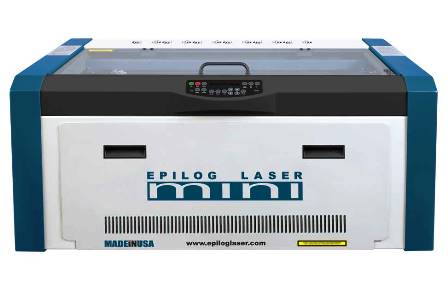
LASER PRINTER - EPILOG MINI
The laser cutter used in our fablab is of the epilog mini series. The laser cutter has an engraving space of 609mmx305mm. The laser uses air to remove heat and combustable gases from the cutting space through an exhaust fan. There is also a red dot pointer to help visualize where the laser will fire. It also has a high memory space to store multiple tasks and allows files of any size to be engraved. the machine has a movable home position feature that allows us to relocate the home position for engraving.
Design using CoralDraw
We begin with the design of the pieces on the Coral Draw software. We are working with two designs to test for the power, speed and kerf and joint clearance.
1. Power and Speed Test 
For the power and speed test, we made an engraving with different power and speeds such that we print them individually and look at the difference. Doing so we can look at the level of power used and difference in the engraving.
The figure below shows the image we have drawn in CoralDraw to look at the difference in power and speed of the laser cutting machine.

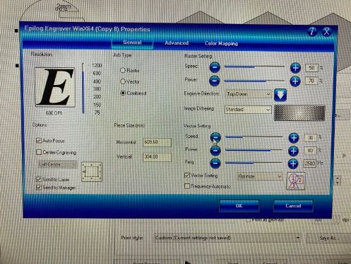
We make necessary settings on the printing software (Auto Focus, Check size of the print and any errors, . Then we look at the Laser Cutter and set appropriate home point for it to start working from.
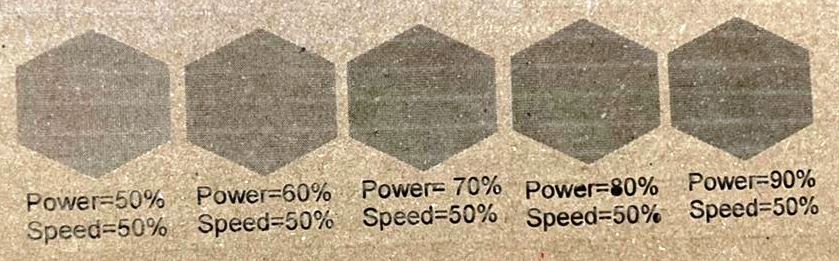
The figure below shows the outcome of the laser cutting.
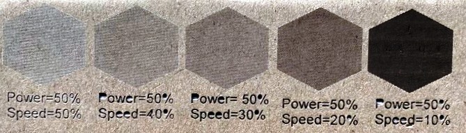
Similarly we have also done with other power and speed levels
A short Video of the working of the Laser Cutting machine is shown below:
Lessons Learnt
- High power and lower speed laser cutting causes the board to burn out on the surface.
- Lower Power only cuts the surface of the board and not through.
- Therefore, need to select the power and speed appropriately such that the cut are proper with least burnout of materials.
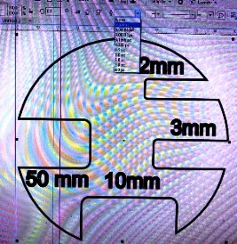
2. Kerf and Joint Clearnace 
For the Kerf and Joint clearance, we worked on designing a shape with slots and cut it with the laser cutter. Then, using vernier caliper we measured the thickness and width of the slots to look at the errors in cutting. The figure below shows the shape we have made in CoralDraw software and cut is shown below that.
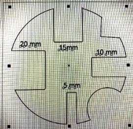
The laser cut piece of the above design is shown below:
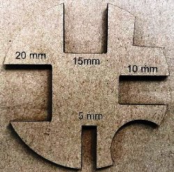
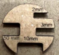
We measured the slot sizes using vernier caliper and compared with the given dimensions. It was observed that there was less than 0.1mm of difference in the slot width and length printed with the laser cutter. Therefore we considered the laser cutter to be pitched with an error of less than 0.2mm.
Using the data received in the group assignment, we edited the parametric design for individual assignment.