10. Output Devices
This week was output devices week. We worked on looking at the poer consumption of output devices in group while I worked on getting a motor running using Attiny controller and motor driver.
The group and individual assignments are as follows:
Group Assignment:
- Measure the power consumption of an output device. The link to the group page is available at Group Assignment
Individual Assignment:
- Add an output device to a microcontroller board you have designed, and program it to do something.
Circuit Design
Schematic Design
This week i will be working at building a motor driver circuit using Attiny to run a DC motor. In my final Project I will be making use of two motors as driving wheel for the Crawler Tank and this week will be practice week to build the circuit and test the operation of the motor.
I begin with the Schematic design in Eagle software which i have been using from the first session and have gotten used to. The basic starting and getting used to Eagle is in the Week6 - Electronics Design. I have documented details of working with Eagle where i made a hello world board and blinking of LED.
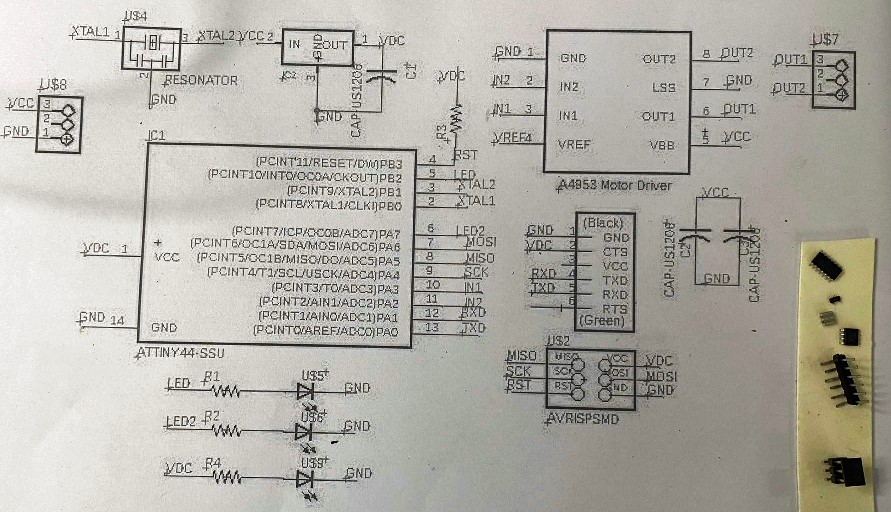
This week i begin again with Attiny controller. Attiny has 14 pins of which two are Vcc and Ground. I make use of four other pins for programming using AVRISP(MOSI, MISO, SCK and RST). This way I am left with 8 pins. I also make use of two other pins for Rx and Tx to connect a FTDI pin connector. The preliminary circuit in shown below.
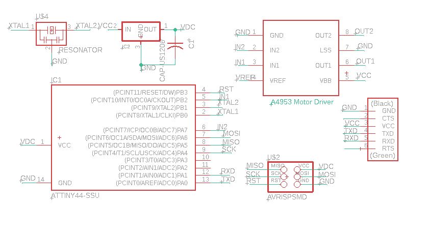
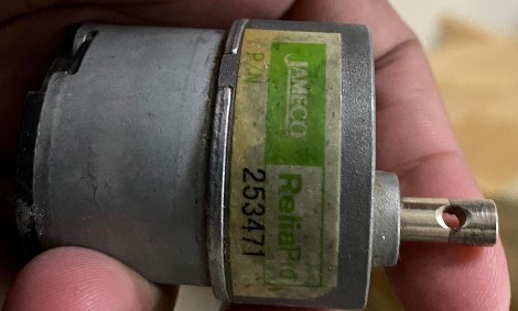
The motor driver i am using the the A4953. The 8 pin, H-Bridge driver is designed for pulse width modulated (PWM) control of DC motors, the A4952 and A4953 are capable of peak output currents to ±2 A and operating voltages to 40 V Datasheet of Driver. The peak current of the motor i am using is 1A and runs at 12V supply. It requires the voltage supply for the motor, a reference voltage of Vref. I am using Vref equal to Vcc after refering to Neil’s Driver circuit at Driver Circuit.
With the above connections made, I still have two pins free from the Attiny44 controller. Therefore I make use of them as signal pin to LEDs that signals the direction of the movement of the motor.

Since the motor runs at 12V while the controller runs at 5V, I am making use of a voltage regulator curcuit. The regulator provides a voltage of 5V at 100mA current. This should be enough to run the Attiny controller and few LEDs. While the external voltage supply of 12V will be supplied in parallel to the Motor Driver circuit.

Further, I make use of a power LED and capacitors closer to the motor diver side to protect from surges. The final schematic circuit is shown below.

Board Design
With the schematic design completed, I move on to design of Board. I the board design, i drag all components to the board window and drag individual components to the desired location. The controller is centered, the power supply and regulator is kept on the left side while the driver is kept on the right. I referred to the Neil’s board for easy design.
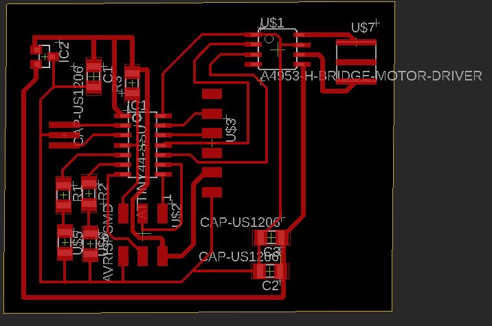
In the routing, I am making use of larger trace width for Power and Vcc lines at 0.508mm while the signal traces are 0.3048mm. I do manual routing for the entire circuit with only two traces running through the controller while no traces run between the pins.
Then i perform DRC check for the design with the following settings.

![]()
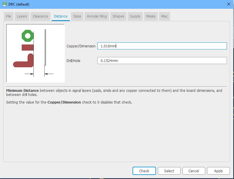
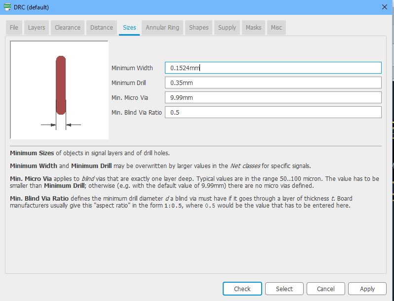
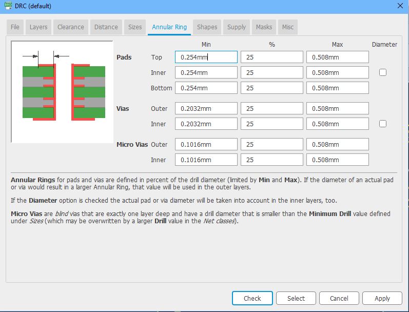
Initially there were few wire stubs remaining on the board design which i rectified to remove all errors. Then i export the board design in monochrome png file format.
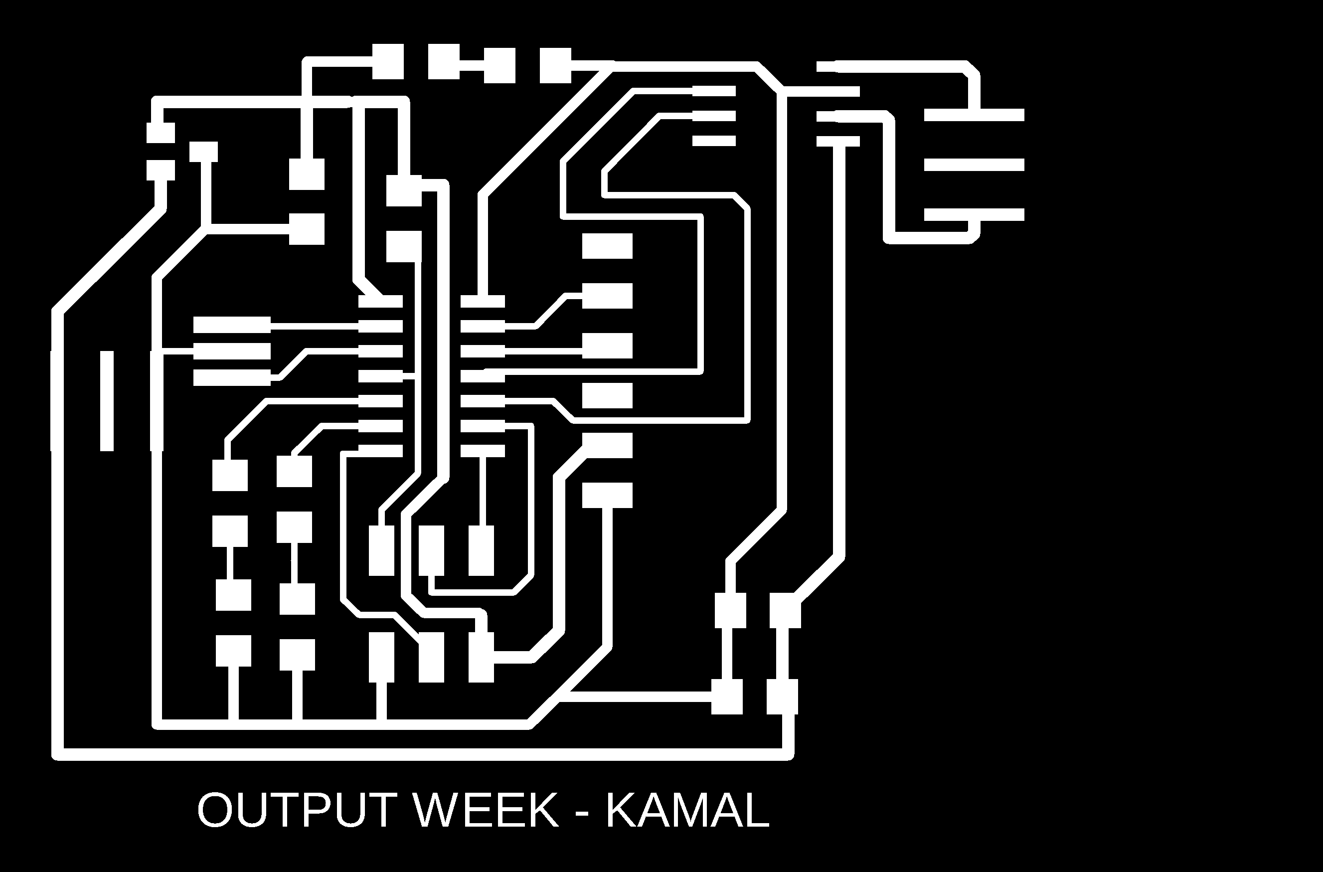
The boarder for the board is shown below.

Initially, I made screw holes along the boarder of the board, however while printing the board, the size of the holes were not considered properly and the board cut and screw hole didnot align properly. I had to remove the holes while milling and rerun the boundry cut a second time to be able to remove the board properly.

Milling the Board
The use of SRM20 milling machine is shown in Week 4- Electornic production week. With the board desing completed i take the png file for the trace and cut to mods and generate machine code (g-code) for SRM20 to mill. I make use of mods to generate the g-code. The details of that is also available in week4.

The milling and cut of the board is complete and i remove the the board for inspection. upon close inspection, i see that i have made a large trace width that passes between a component because of which the SRM20 left a small part without removing the traces. Since it was a small strectch, i remove the trace using knife and test for short using multimeter.

As seen in the image above, There was a small portion that was not properly milled by the SRM20, probably because i made some mistake in the DRC check. However, after removing the overlapping portions, I tested for shortcircuit and it was functional.
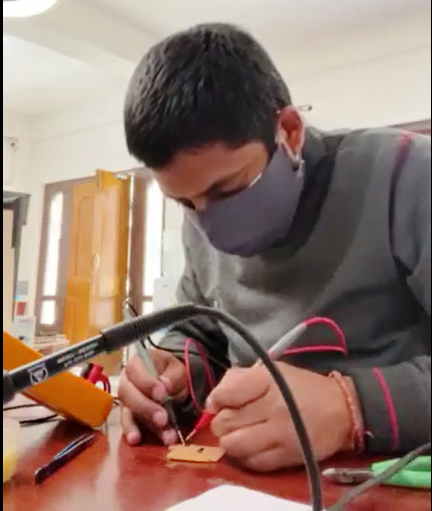
Soldering the components.
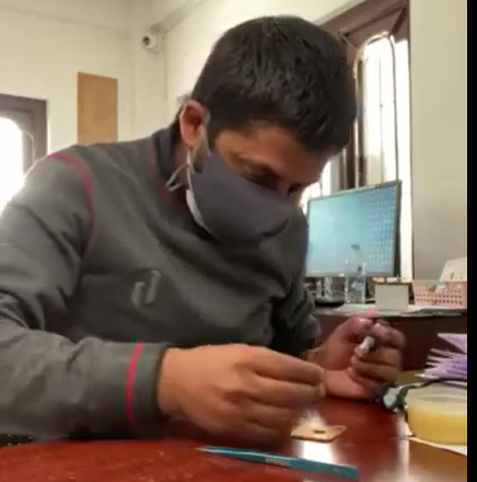
With the board milled, i move on to collecting the components and soldering them on the board.
I start the soldering with controller and driver first. The shorter and harder components are soldered first followed by resistors, LEDs and finally the connectors.

After soldering each components, I also use connectivity test to check if all solder connects the pins to the board. This way, it will eliminate the requiement of major debugging later.
Initially i made a pin header to connect power source, but while checking the inventory for components, i came across a female power socket. I tried to align the socket to the pin header slot i created on the board and it was aligning properly. Therefore, at soldering phase I changed the pin header with the socket.
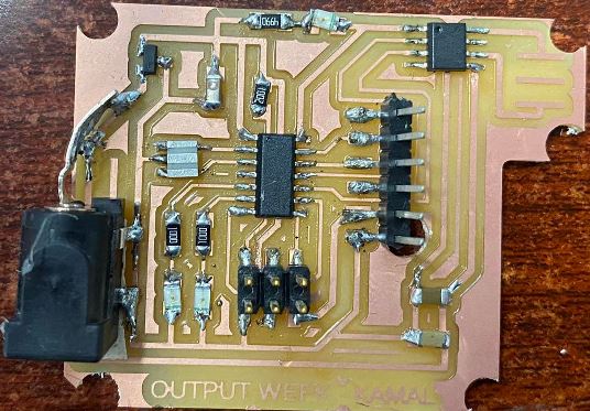
With the soldering of the components completed, I check to see if the power LED is working then I move on to programming and testing of the board.

Board Programming and Testing.
In the board programming, I am making use of Arduino as ISP. I make the necessary connections of the board ISP pins with the desired pins in on the Arduino board. I use Arduino as ISP and program the board before connecting the board to the motor. The connection of Attiny board with Arduino is found HERE

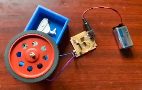
With the board programmed (Program in the section below), I connect the motor to the board and check the operation of the device.
Code for Motor and LED
This code first provides low to all pins, Then turns the Motor in one direction while turning an LED for two seconds. Powers all Pins Low, Then it will turn the Motor in anticlock wise direction and glows another LED.
//ATtiny Pin5,6 - LED Arduino (8,7)
//Attiny Pin 10,11 - in1,in2 Arduino (3,2)

#define MOTOR1 3
#define MOTOR2 2
#define LED1 8
#define LED2 7

void setup()
  {
// put your setup code here, to run once:
pinMode(LED1, OUTPUT);
pinMode(LED2, OUTPUT);
pinMode(MOTOR1, OUTPUT);
pinMode(MOTOR2, OUTPUT);
  }

void loop()
  {
    digitalWrite(MOTOR1, LOW);
    delay(10);
    digitalWrite(LED1, LOW);
    delay(10);
    digitalWrite(MOTOR2, LOW);
    delay(10);
    digitalWrite(LED2, LOW);
    delay(10);

    motorright();
    motorleft();
  }

void motorright()
{
    digitalWrite(MOTOR1, HIGH);
    digitalWrite(LED1, HIGH);
    delay(100);
    digitalWrite(MOTOR1, LOW);
    digitalWrite(LED1, LOW);
    delay(100);
   }

void motorleft()
{
    digitalWrite(MOTOR2, HIGH);
    digitalWrite(LED2, HIGH);
    delay(100);
    digitalWrite(MOTOR2, LOW);
    digitalWrite(LED2, LOW);
    delay(100);
  }
Video
Output week-10 Process
Project Files
- Eagle Project File: Eagle Project File
- RML file from MODs RML Files