27. Group Assignment Week 12 - Input Devices
This week we are working on connecting input devices to our boards and looking at their output for group assignment. The following is the group assignment.
Group Assignment
- Probe an input device’s analog levels and digital signals
Group Members:
Test Equipments in Lab
- CRO
Testing with CRO
Multimeter are good at measuring DC voltages however are not particularly effective and useful at measuring signal voltages that are pulse in nature with high frequency. Therefore, We make use of CRO to check the pulse volatages on the board. We used it to look at the frequency generated by the crystal oscillator.
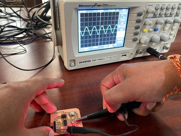
Then we measured the pulse output generated when switchig the LED On and Off. This way we can visuallize the operation of the circuit board when switching an LED.

Measuring Data of Ultrasonic Sensor
For the testing of the output of Ultrasonic sensor, we have three terminals to connect. We connect the Vcc and GND pins of the sensor to the Vcc and GND pin of the controller board. We can also provide these inputs from DC voltage supply board with 5V output. Since the current requirement of ultrasonic sensor is low, we can make use of low power supply or a battery supply. We tried powering the sensor module using DC battery through the board. On the CRO, we connect the CRO probe to the suitable port and connect the ground to the ground of supply while we connect the positive probe to the signal pin of the sensor.
The circuit connection is shown below:

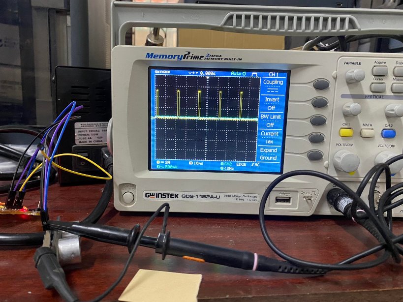
With the probe connected to the trigger pin, we were able to visuallize the trigger pulse sent by the sensor. The trigger pulse has a 10us Ton pulse width and 4us Toff pulse width. The pulse can be visuallized on the CRO as below:

Similarly, for the Ultrasonic sensor, we can also look at the output of the echo pin based on the signal receive by the sensing sensor. For the same, we make use of the input board and connect three pins to the controller and the sensor as : Vcc, GND and Trigger. With these connected and powered, we can connect the CRO probe to the echo pin of the sensor to look at the signal received by the sensor from the reflection of trigger signal.
We can also vary the distance between the sensor and object and look at the change in the signal from the echo pin.
From changing the distance of the object, we could see that there is change in the pulse width of the signal being recorded in the CRO as shown below:
Measuring Data of PIR Sensor
For the testing of the output of PIR sensor, we have three terminals to connect. We connect the Vcc and GND pins of the sensor to the Vcc and GND pin of the controller board. We can also provide these inputs from DC voltage supply board with 5V output. Since the current requirement of PIR sensor is low, we can make use of low power supply or a battery supply. We tried powering the sensor module using DC battery through the board. On the CRO, we connect the CRO probe to the suitable port and connect the ground to the ground of supply while we connect the positive probe to the signal pin of the sensor.
The circuit connection of PIR sensor connected to Attiny board and CRO is shown below:

The output of the PIR sensor is Digital output based on whether IR radiation is detection or not. This can be visuallized on the CRO for change in the state of the Digital output of the PIR sensor when it detects IR radiations.
The outcome can also be seen in the figure above. The working is shown in the video below: