12. Input Devices
This week I worked connecting a couple of input devices to a board I have designed.
The group and individual assignments are as follows:
Group Assignment:
- Probe an input device’s analog levels and digital signals
The link to the Group Assignment is available HERE
Individual Assignment:
- Measure something: add a sensor to a microcontroller board that you have designed and read it
Starting Point
Schematic Design
This week i want to try designing a board using Attiny1614. Since the Eagle library for the same is not available on fab libraries, I am downloading the library from: www.snapeda.com
In my final Project I will be making use of two motors as driving wheel for the Crawle Tank including a couple of input sensors for obastcle and camera. Therefore, this week I will practice to build the circuit and test the working of input sensors with the board.
I begin with the Schematic design in Eagle software which i have been using from the first session and have gotten used to. The basic starting and getting used to Eagle is in the Week6 - Electronics Design. I have documented details of working with Eagle where i made a hello world board and blinking of LED.
This week i begin again with Attiny1614 controller. Attiny has 16 pins of which two are Vcc and Ground. I make use of one pin for programming using UPDI programmer. This way I am left with 13 pins. I also make use of two other pins for Rx and Tx so that I can have serial connections if I connect to USB or to other devices for communication. This way, I can make use of all the pins in the Attiny. I have added three LEDs in the board for output while I have kept three pins for input devices. The simulation of the circuit in this case will be based on the change in the state of the output devices with the input devices as trigger. The preliminary circuit in shown below.

With the above connections made, I still have few pins free from the Attiny1614 controller. But at this point I have left them open without any connections.
Board Design
With the schematic design completed, I move on to design of Board. I the board design, i drag all components to the board window and drag individual components to the desired location. The controller is centered, the components are aligned such that there is least overhead in the routing process. i changed the pins a bit so that the routing becomes easier.
In the routing, I am making use of larger trace width for Power and Vcc lines at 0.508mm while the signal traces are 0.3048mm. I do manual routing for the entire circuit with only two traces running through the controller while no traces run between the pins.
Then i perform DRC check for the design with the following settings.


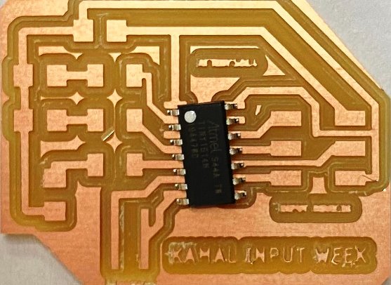
The final board design is shown below:

Initially there were few wire stubs remaining on the board design which i rectify to remove all errors. Then i export the board design in monochrome png file format at 1000dpi.

The boarder for the board is shown below.

With the board design successful, I move on to mill the board as follows:
Milling the Board
The use of SRM20 milling machine is shown in Week 4- Electornic production week. With the board desing completed i take the png file for the trace and cut to mods and generate machine code (g-code) for SRM20 to mill. I make use of mods to generate the rml file. The details of that is also available in week4.

Then I move on to milling of the board as shown in the video below:
The milling and cut of the board is complete and i remove the the board for inspection. upon close inspection, i see that the SRM had not milled the copper completely and left few traces without milling. I milled the board again successfully. The board is shown below:
Soldering the components.
With the board milled, i move on to collecting the components and soldering them on the board.
I start the soldering with controller first followed by smaller components and finally the headers. The shorter and harder components are soldered first followed by resistors, LEDs and finally the connectors.
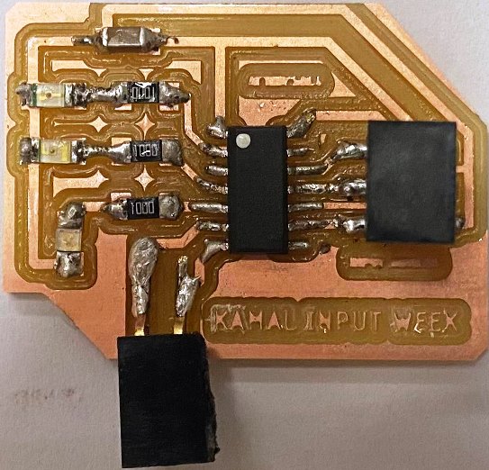
After soldering each components, I also use connectivity test to check if all solder connects the pins to the board. This way, it will eliminate the requiement of major debugging later.
Installing Tiny Cores for Arduino IDE
Since the Arduino core is not preinstalled in Arduino IDE, I have to install the core libraries in Arduino. Before that, I install the pyupdi using the code below. This will allow for UPDI programmer to program the Attiny1614 controller.
pip install intelhex pylint pyserial
With the PyUPDI installed, I proceed to installing the library for the Attiny1614 using the library available at: megaTinyCore I made use of the JSON file available at: Electronics-Lab
http://drazzy.com/package_drazzy.com_index.json

With the Board Library added to Arduino IDE. The library will be available in the Arduino IDE.

I choose the programmer as Serial UPDI:
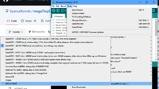
Then I select the port as available and run the bootloader first.

After running the bootloader, I load the code to the 1614 controller board.

Input Devices.
There are a number of input devices we learnt about in the global lecture and also following Adrianino’s page. The following input devices are available for us in the lab and i want to make use of individual sensors connected to the I/O ports in Attiny44 board I have designed to test their functionality.
Push Button
The use of button as input device was tested in the Electronics design week Here where we connected a push button as input devices and blink a LED.
Ultrasonic Sensor
The HC-SR04 ultrasonic sensor uses sonar to determine distance to an object like bats do. It offers excellent non-contact range detection with high accuracy and stable readings in an easy-to-use package. It comes complete with ultrasonic transmitter and receiver modules. (Source: Adrianino Page)

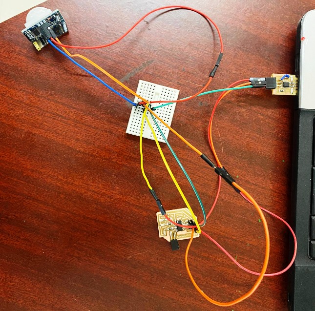
The Ultrasonic sensor has four outputs, two of the pins are connected to VCC and GND respectively while the other two are trigger pin and echo pins. Therefore we would need four pin connector for our case connected to the controller board. The connection diagram for inputs and outputs with the Attiny controller is shown below:

With reference to the above circuit, I connect the ultrasonic sensor to the Attiny board. The connection is as follows:
- Vcc to Vcc pin of Sensor
- GND to GND pin of Sensor
- Trigger to I/O of Attiny
- Echo to I/O of Attiny
- LEDs to I/O of Attiny
With the above connection established, I change the program code as follows:
//Fab Academy 2022 - Fab Lab Bhutan US-Sensor Kamal

#define LEDR 0
#define LEDG 2
#define LEDB 3

#define EchoPin 8
#define TriggerPin 7
long duration;
int distance;

byte EchoRead=LOW;

void setup() {
  pinMode(LEDR, OUTPUT);
  pinMode(LEDG, OUTPUT);
  pinMode(LEDB, OUTPUT);
  pinMode(TriggerPin,OUTPUT); // ArduinoPin 1
  pinMode(EchoPin,INPUT); //Arduinopin 0
}

void loop() {
  // Sending trigger pulse at 10uS.
      digitalWrite(TriggerPin, LOW);
      delayMicroseconds(2);
      digitalWrite(TriggerPin, HIGH);
      delayMicroseconds(10);
      digitalWrite(TriggerPin, LOW);

      duration = pulseIn(EchoPin, HIGH);
      distance = duration * 0.034 / 2; // Speed of sound wave divided by 2 (go and back)

      if(distance <10)
      {
        blinkred();
        }
        else if(distance >10 && distance <50)
        {
          blinkgreen();
          }
          else if (distance >50 && distance <100)
          {
            blinkblue();
            }
            else {
              AllLow();
              }
   }

void blinkred()
 {
  digitalWrite(LEDR, HIGH);
  delay(10);
  digitalWrite(LEDR, LOW);
  delay(10);
  digitalWrite(LEDR, HIGH);
  delay(10);
  digitalWrite(LEDR, LOW);
  delay(10);
  digitalWrite(LEDR, HIGH);
  delay(10);
  digitalWrite(LEDR, LOW);
  }

void blinkgreen()
{
  digitalWrite(LEDG, HIGH);
  delay(10);
  digitalWrite(LEDG, LOW);
  delay(10);
  digitalWrite(LEDG, HIGH);
  delay(10);
  digitalWrite(LEDG, LOW);
  delay(10);
  digitalWrite(LEDG, HIGH);
  delay(10);
  digitalWrite(LEDG, LOW);
  }

void blinkblue()
{
  digitalWrite(LEDB, HIGH);
  delay(10);
  digitalWrite(LEDB, LOW);
  delay(10);
  digitalWrite(LEDB, HIGH);
  delay(10);
  digitalWrite(LEDB, LOW);
  delay(10);
  digitalWrite(LEDB, HIGH);
  delay(10);
  digitalWrite(LEDB, LOW);
  }

void AllLow()
{
  digitalWrite(LEDR, LOW);
  digitalWrite(LEDG, LOW);
  digitalWrite(LEDB, LOW);
  }
With the program updated, I first run the bootloader on UPDI board, The I burn the Attiny board with UPDi programmer.
The logic for the above code is: When the distance is less than 10cms, the LED Red will blink, while the LED Green will blink when the distance is more than 10 and Less than 50. Beyond 50, the LED Blue will blink.
The working of the above is shown in the video below:
Passive Infrared (PIR) Sensor
A passive infrared sensor (or PIR sensor) is an electronic sensor that measures infrared (IR) light radiated from objects in its field of view. They are mainly used in PIR-based motion detectors.
The PIR sensor has three outputs, two of the pins are connected to VCC and GND respectively while the third pin is the data pin. Therefore we would need three pin connector for our case connected to the controller board. The connection diagram for PIR sensor with the Attiny controller is shown below:
With the above connection established, I change the program code as follows:
#define LEDR 0
#define LEDG 2
#define LEDB 3

#define EchoPin 8

byte EchoRead=LOW;

void setup() {
  pinMode(LEDR, OUTPUT);
  pinMode(LEDG, OUTPUT);
  pinMode(LEDB, OUTPUT);
  //pinMode(TriggerPin,OUTPUT); // ArduinoPin 1
  pinMode(EchoPin,INPUT); //Arduinopin 0
}

void loop() {
  // Sending trigger pulse at 10uS.
      EchoRead = digitalRead(EchoPin);

      if(EchoRead == 0)
      {
        blinkred();
        }
        else if(EchoRead == 1)
        {
          blinkgreen();
          blinkblue();
          }
           else {
              AllLow();
              }
   }

void blinkred()
 {
  digitalWrite(LEDR, HIGH);
  delay(10);
  digitalWrite(LEDR, LOW);
  delay(10);
  digitalWrite(LEDR, HIGH);
  delay(10);
  digitalWrite(LEDR, LOW);
  delay(10);
  digitalWrite(LEDR, HIGH);
  delay(10);
  digitalWrite(LEDR, LOW);
  }

void blinkgreen()
{
  digitalWrite(LEDG, HIGH);
  delay(10);
  digitalWrite(LEDG, LOW);
  delay(10);
  digitalWrite(LEDG, HIGH);
  delay(10);
  digitalWrite(LEDG, LOW);
  delay(10);
  digitalWrite(LEDG, HIGH);
  delay(10);
  digitalWrite(LEDG, LOW);
  }

void blinkblue()
{
  digitalWrite(LEDB, HIGH);
  delay(10);
  digitalWrite(LEDB, LOW);
  delay(10);
  digitalWrite(LEDB, HIGH);
  delay(10);
  digitalWrite(LEDB, LOW);
  delay(10);
  digitalWrite(LEDB, HIGH);
  delay(10);
  digitalWrite(LEDB, LOW);
  }

void AllLow()
{
  digitalWrite(LEDR, LOW);
  digitalWrite(LEDG, LOW);
  digitalWrite(LEDB, LOW);
  }
The logic for the above code is:
When no motion is detected, the LED RED will Blink, while the LED Green and LED Blue will flicker at millisecond speed when motion is detected.
The working of the above is shown in the video below:
For the PIR Sensor, I have found that there is a delay of few seconds between motion detection and Output display.
Temperature and Humidity Sensor (DHT11)
DHT11 Temperature & Humidity Sensor features a temperature & humidity sensor complex with a calibrated digital signal output. By using the exclusive digital-signal-acquisition technique and temperature & humidity sensing technology, it ensures high reliability and excellent long-term stability. This sensor includes a resistive-type humidity measurement component and an NTC temperature measurement component, and connects to a highperformance 8-bit microcontroller, offering excellent quality, fast response, anti-interference ability and cost-effectiveness (Source: Datasheet).

The DHT11 comes with 3-Pins or 4-Pins, The one i am using for this week has three pins namely: Vcc, GND and Out. To check the functionality of the DHT11, I first connected the device to the Arduino Board and visuallized the range of temperature and Humidity on serial monitor. The circuit for the test is shown below:

With the above connection established, I change the program code as follows:
//***************************************************************//
//          : Measure Humidity and Temperature by DHT11          //
//***************************************************************//

// Include DHT library
#include "DHT.h"
#define LEDR 0
#define LEDG 2
#define LEDB 3

// DHT11 is conneted to pin 4
#define DHTPIN 8
// Use DHT11 in DHT series
#define DHTTYPE DHT11

// Create DHT object to get data from DHT11
DHT dht(DHTPIN, DHTTYPE);

// Initialisation
void setup() {
  // Initialise DHT11
  pinMode(LEDR, OUTPUT);
  pinMode(LEDG, OUTPUT);
  pinMode(LEDB, OUTPUT);
  dht.begin();
  // Initialise Serial Monitor
//  Serial.begin(9600);
}

// Main loop
void loop()
{
  float  humidity, temperature;
  // Read humidity from DHT11
  humidity    = dht.readHumidity();
  // Read temperature from DHT11
  temperature = dht.readTemperature();

if(temperature < 20 && humidity <50 )
      {
        blinkred();
        }
        else if(temperature > 20 && humidity >50 )
        {
          blinkgreen();
          }
           else {
               blinkblue();
              }
   }

void blinkred()
 {
  digitalWrite(LEDR, HIGH);
  delay(10);
  digitalWrite(LEDR, LOW);
  delay(10);
  digitalWrite(LEDR, HIGH);
  delay(10);
  digitalWrite(LEDR, LOW);
  delay(10);
  digitalWrite(LEDR, HIGH);
  delay(10);
  digitalWrite(LEDR, LOW);
  }

void blinkgreen()
{
  digitalWrite(LEDG, HIGH);
  delay(10);
  digitalWrite(LEDG, LOW);
  delay(10);
  digitalWrite(LEDG, HIGH);
  delay(10);
  digitalWrite(LEDG, LOW);
  delay(10);
  digitalWrite(LEDG, HIGH);
  delay(10);
  digitalWrite(LEDG, LOW);
  }

void blinkblue()
{
  digitalWrite(LEDB, HIGH);
  delay(10);
  digitalWrite(LEDB, LOW);
  delay(10);
  digitalWrite(LEDB, HIGH);
  delay(10);
  digitalWrite(LEDB, LOW);
  delay(10);
  digitalWrite(LEDB, HIGH);
  delay(10);
  digitalWrite(LEDB, LOW);
  }
When the Temperature is less than 20 and Humidity is less than 50 , LED RED will blink. If Temperature is more than 20 and Humidity is more than 50, LED Green will blink. Else LED Blue will blink.
With the above code uploaded to the Controller. The working of the system is shown Below.