9. Molding and Casting
This week was molding and casting week. We worked on looking at the different moulding and casting material in group while I worked on making a mold and casting simple objects this week.
The group and individual assignments are as follows:
Group Assignment:
- Review the safety data sheets for each of your molding and casting materials, then make and compare test casts with each of them
- Extra credit: Try other molding and casting processes
Individual Assignment:
- Design a mold around the stock and tooling that you’ll be using,
- Mill it (rough cut + three-axis finish cut), and use it to cast parts
- Extra credit: use more then two mold parts
Group Assignment
In group assignment we looked at different molding and casting materials and their specifications. The details are available HERE
Individual Assignment
Starting Point
Initially, I planned on making a stamp for myself. The stamp was also designed using fusion360 and was imported for milling in SRM20.
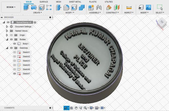
However, after i imported it to the Modela Player to generate the G-code, I realize that the size and spacing of text was much smaller than the size of endmill. Therefore, I discarded the idea and proceeded to another design.
Therefore, for the individual assignment, I am working on a design i have for my final project. The details of the project and designs are available at Project Section. In the project, I have designed a sprocket to connect to the motor and the tank track. This sprocket has a inner 5cm diameter. I designed it using Fusion360 and made use of tutorial from Youtube
Designing on Fusion360
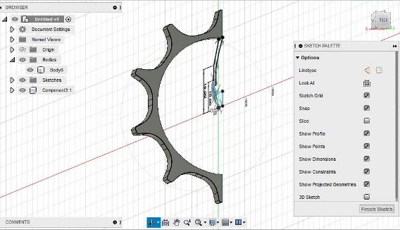
For the design of sprocket, I use a circle of diameter 5cm and start by creating the tooth along side it.

Then i make use of arc tools to make the tooth and further use circular pattern tool to create the tooths along the circular structure.

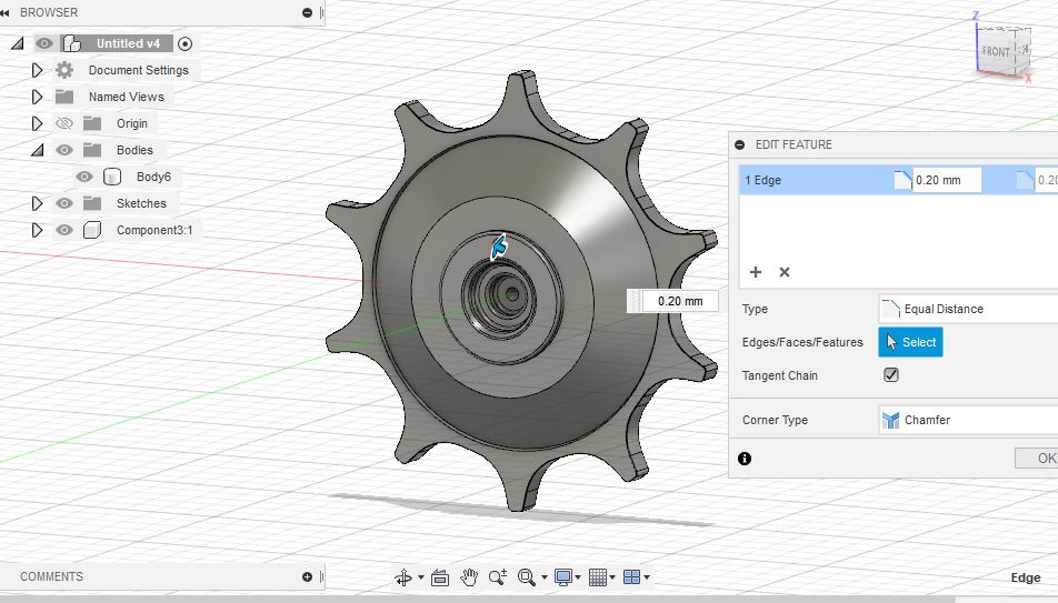
Then, I use split tool to make a mould shape in the middle and use revolve tool to create a circular body. Then i make drill holes along the centers that can be used to properly allign and connect the motor in place.
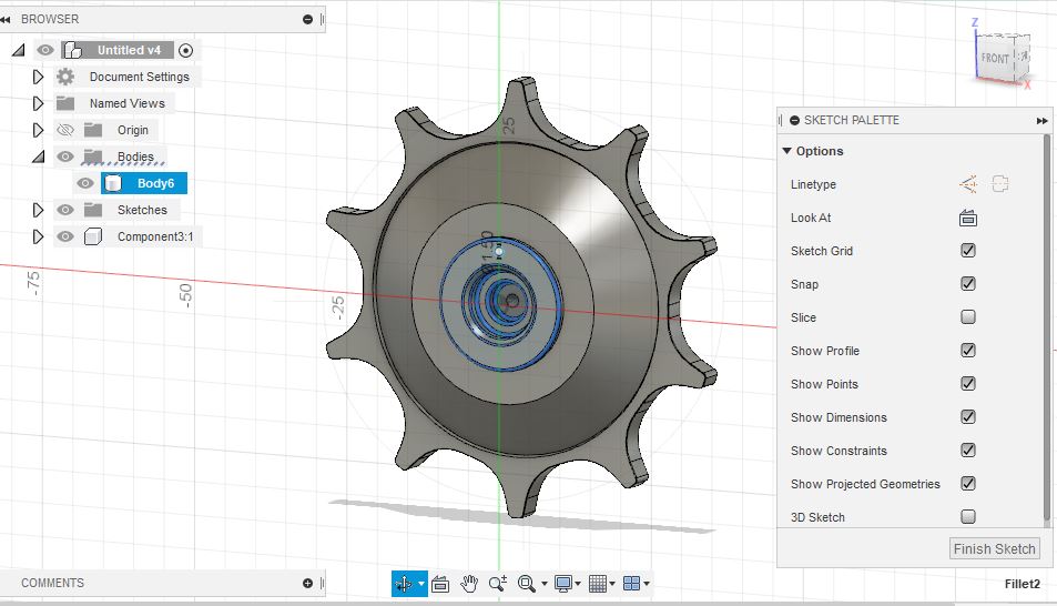
The final shape of the design is as shown below:
The 3D design file is shown below: The design file has changed significantly since the Molding Casting week till the end due to iterations in Project requirements
Milling on SRM20
With the 3D design completed, I move to milling on SRM20. The detail of SRM20 in our lab is in Week4 - Electronic Production
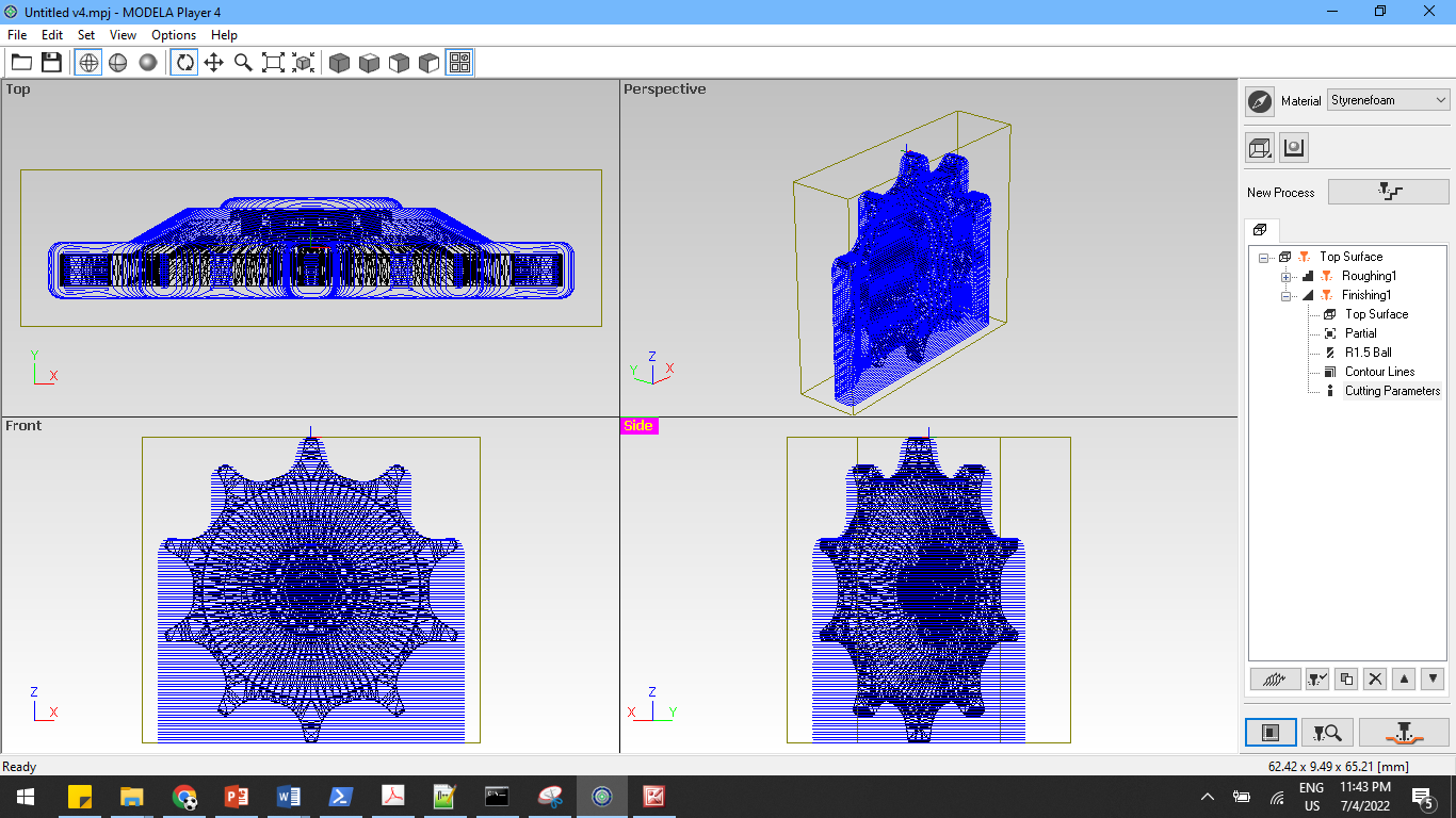
Firstly, I import the file to Modela Player. The modela player uses the .stl design file to create roughing and smoothing toolpath for the SRM20. In Modela Player, I first open the .stl file.

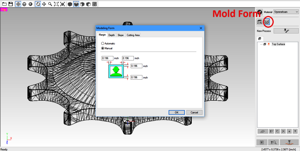
Then, i set the orientation of the object i have designed such that the orientation of the design would cut the top surface.


Then, we select single sided cut and modify the moulding settings. We keep a 5mm spacing around the object so as to have space in the molding process.
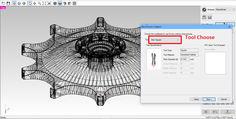
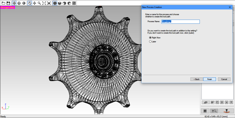
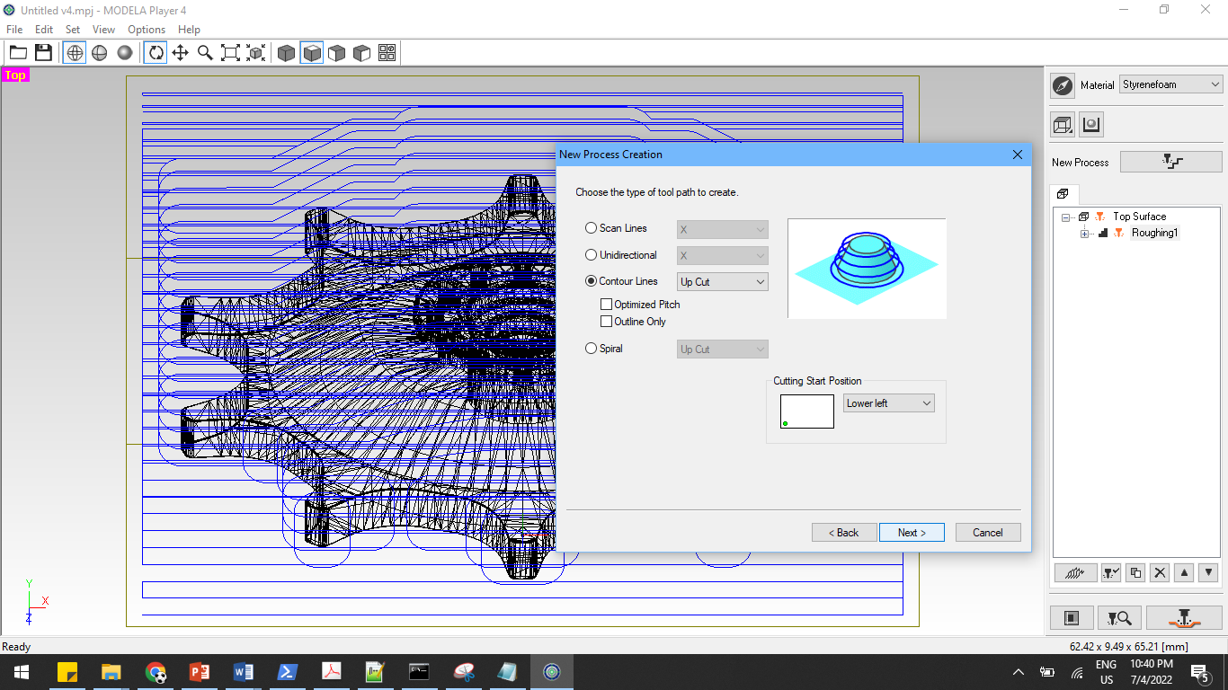
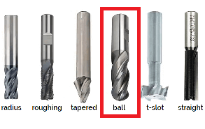
Then we make a new process and set the size of required endmill. For the current case, we are making use of two flute, 3.175square endmill for roughing.

We select the suitable endmill from the dropdown menu and proceed.

Then we select the cutting depth and set the initial z-axis to 5mm. This will cut the first 5mm below the set z-axis and start the molding process after 5mm.
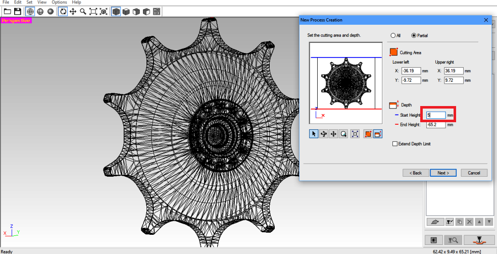
With that, we set the contour to upcut and start point to bottom left.

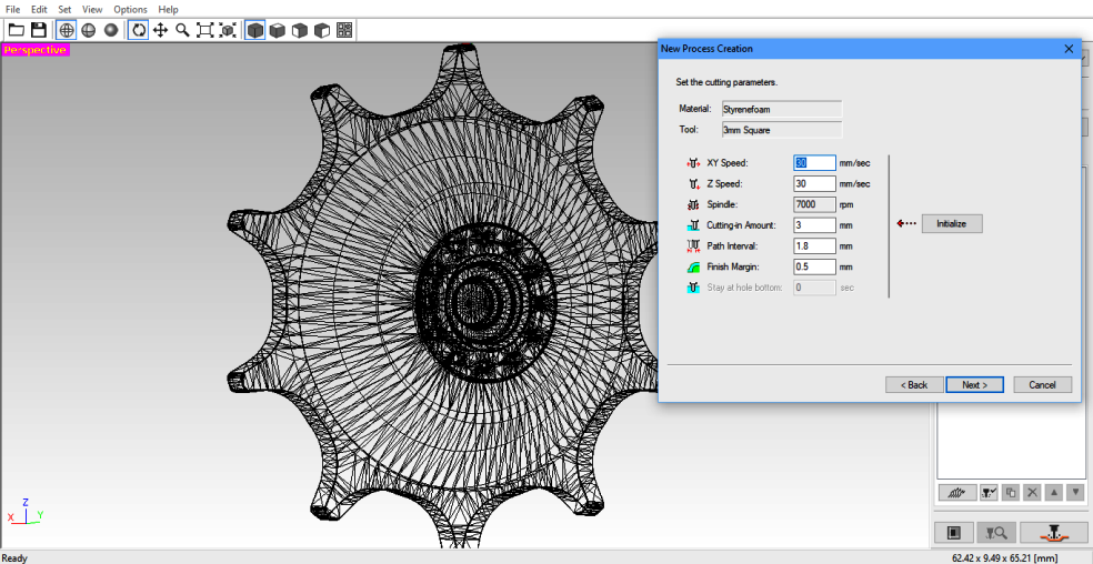
Then we keep the cutting parameters to default.

Next we work on the process of finishing to make clean around the cuts.
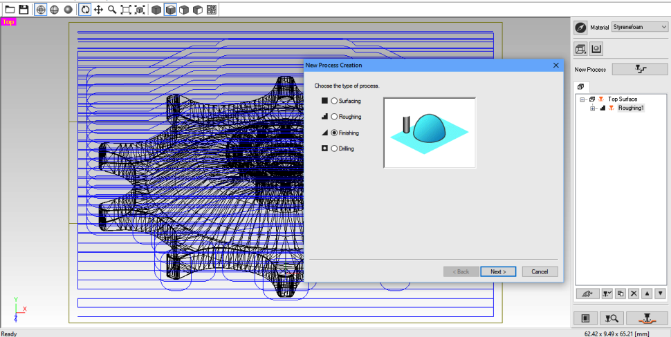
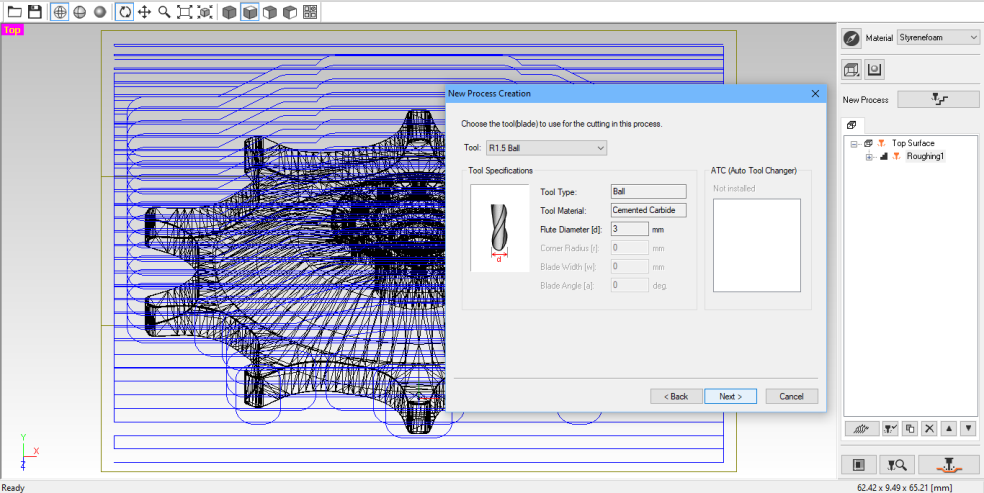
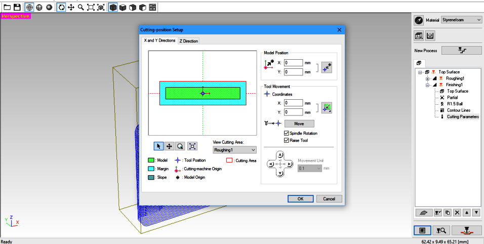
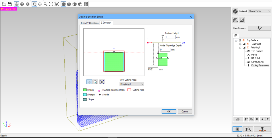
With the finishing process selected, we move on to setting z-point then move on to selecting the tool for the process.

Similarly, we can also change the starting point of the cutting process. We have make sure to add 5mm in the z-direction so that the milling process will begin after 5mm in the z-direction.

Then make the contour lines upcut and lower left.
 Then keep the default cutting parameters as before.
Next we chage the cutting position to make sure XYZ are at zero value.
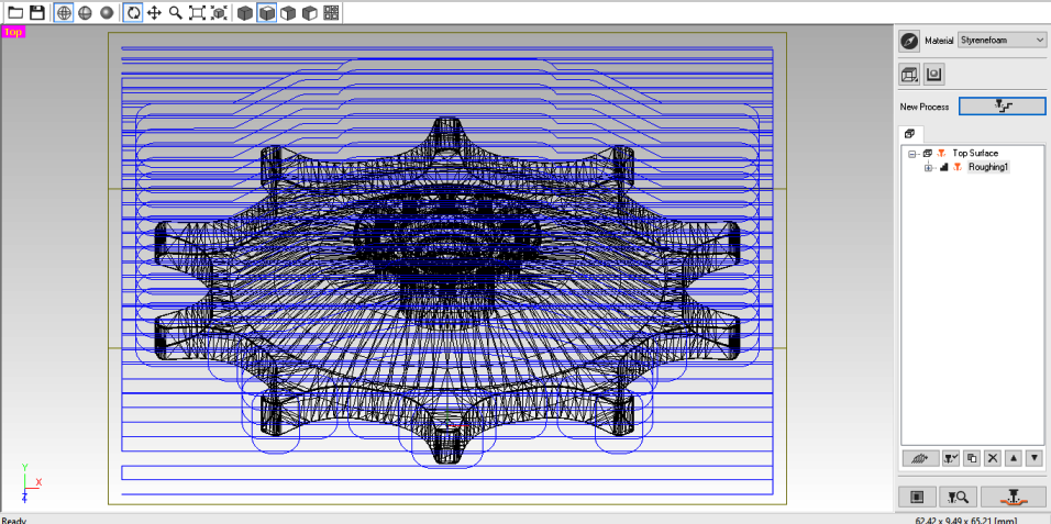
The final tool paths and process looks like below:
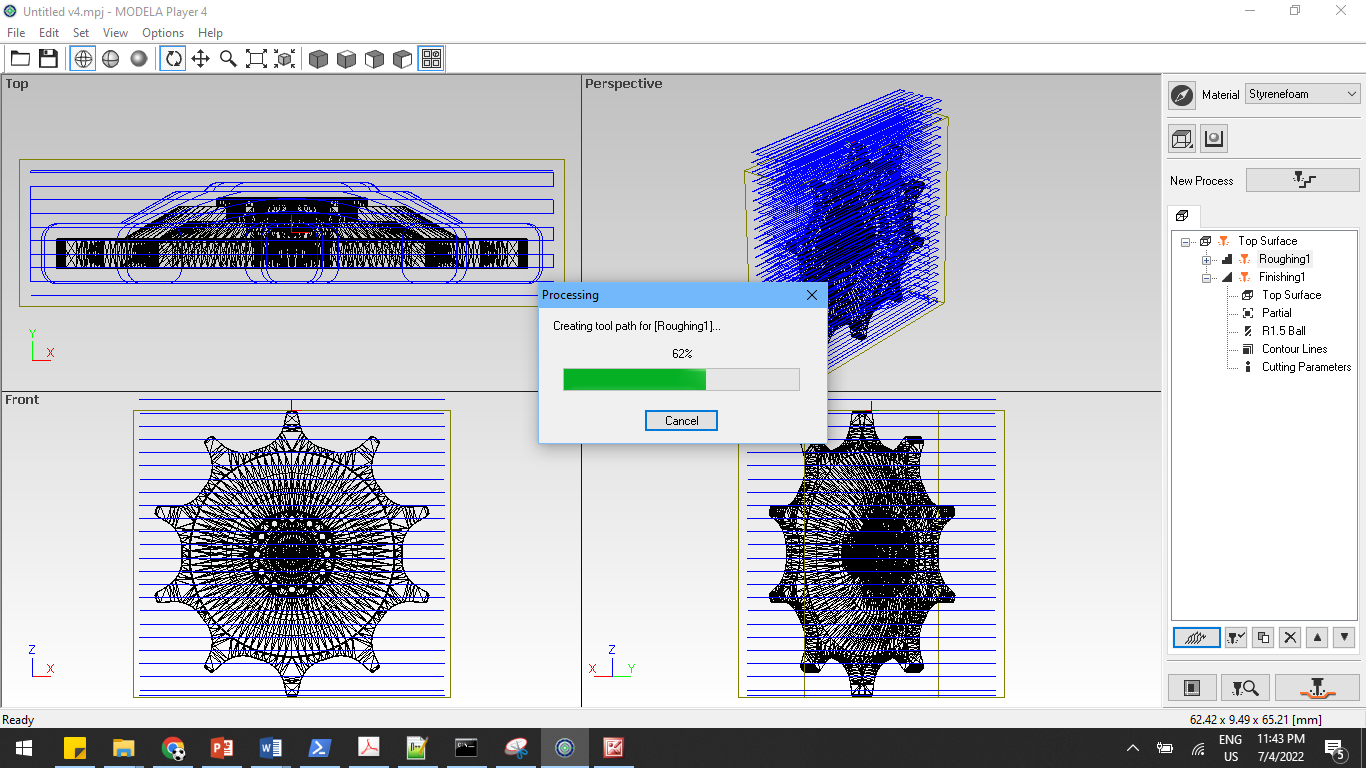
We save the toolpath for the two process of roughing and finishing on our drive. These files are going to be used by SRM20 for milling process.
Then we open the V-panel for SRM20 and set the zero axis. Before that I first take the molding material and fix it on the SRM base plate and label it.

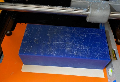
In the current process, we have to set the zero axis at the center of our material. The molding material we are usign has various dimensions. The material i received had a dimension of 15cm x 7cm. In the initial stage, i thought that the size of my design had a diameter of 5cm and forgot to take into account the size of the teeth. Then I proceeded to mill it using the above dimensions.
In order to center the XY on the material, i create two diagonal lines and use the intersecting point as the center. WIth the XY centered and zeroed in V-Panel, I set the Z-axis. The Z is first moved with V-panel and then I make use of gravity method to touch the tip of endmill with the surface of the object.
In the V-panel for SRM, I load the roughing and finishing toolpath from the Modela player and give it to cut. The cut has to first run with the tool path for roughing and then with the toolpath for finishing. For the finishing, I change the end mill to R1.5825 Ball pin tip.
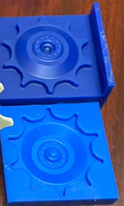
The outcome after the milling process is shown below:
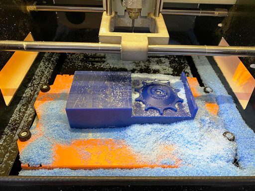
Two sides of the mold were also cut during the milling process because I didnot take care of the size of the tooth of the sprocket. However, I could still make use of the mold with two supports along the sides.
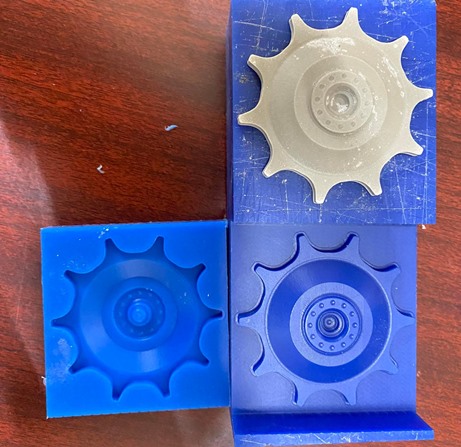
Creating the Negative mold
To create a negative mold of the design, we are making use of silicone molding material part A and Part B in equal proportion. We add them in a single container and mix properly.
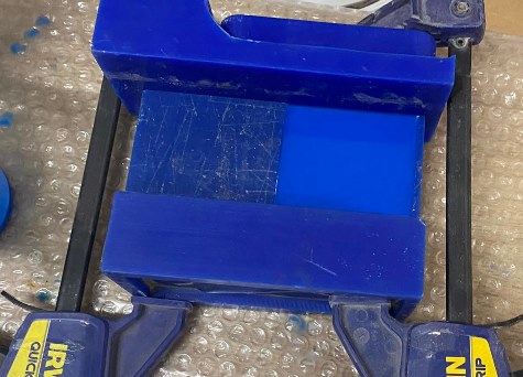
After mixing the two materials, we have to pour it over the initial rubber mold. Since i had two sides of the mold open, I had to use supports on two sides and clamp it together.
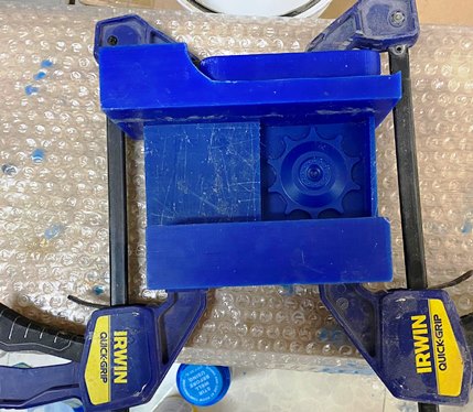
Then i pour the silicone material on the mold very slowly while making sure that there is no air bubbles in the mixture.

We then let it set for a while. Then we remove the negative mold.
Casting with Hydrostone
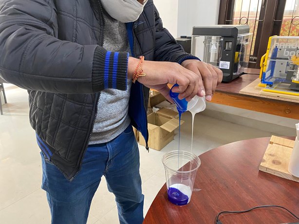
The next process is to cast the hydrostone material on the silicone negative mold. The hydrostone material is mixed in the ratio of 100gm hydrostone powder to 34gm of water. I mix the two together in a container and make sure to not keep any powder unmixed.

We pour the mixture very slowly while making sure that there is no air bubbles in the mixture. Then let it set for few hours.
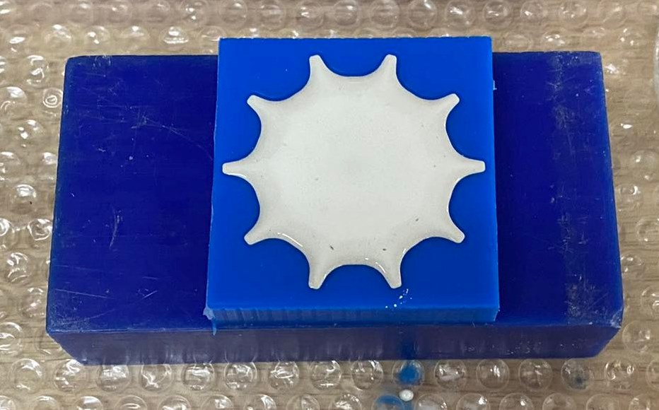
Once the cast is set, we remove it and look at the design.
Two Sided Casting
My design had two parts but the mold was only one sided. I used another trick to cast the material on the mold by casting only upto half of the mold and pressing the previous cast on top of it. After leaving it for a while, I found that the cast did stick well with the pervious cast and now I can have two sided cast. The two side cast is shown below:
The process of all is shown in the video below
Molding and Casting Process Video
Project Files
Sprocket Design
- STL file of initial Design: Initial Design
- STL file of Sprocket Design: Sprocket Design