2. Computer Aided Design
This week I worked on different 2D and 3D softwares to determine the best softwares that i am comfortable with. Firstly i differentiate between raster and vector image type.
Assignments
- Model (raster, vector, 2D, 3D, render, animate, simulate, …) a possible final project,
- Compress your images and videos,
- And post a description with your design files on your class page
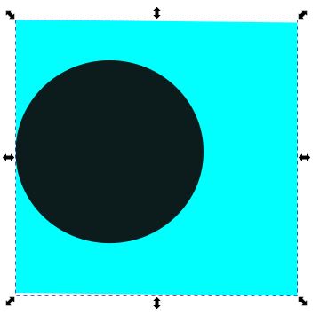
Vector vs Raster Image
A vector image is made up of points and lines and appears smooth. Vector graphics are digital art that is rendered by a computer using a mathematical formula. Raster images are made up of tiny pixels, making them resolution dependent and best used for creating photos. This means that if I scale a vector image, it will maintain a smooth, un-pixelated appearance, whereas a raster image will become pixelated. Defination edited from Pavilion
![]()
![]()
![]()
Figure: Image Depicting the pixelated boundry using raster image (GIMP)
![]()
![]()
![]()
Figure: Image Depicting the non-pixelated boundry using vector image (Inkscape)
In order to understand the softwares better, I worked with individual softwares using tutorials. The first software I tried is GIMP and for vector is Inkscape. While Inkscape is easier to use and manupulate for creating graphics, GIMP is easier for scaling image.
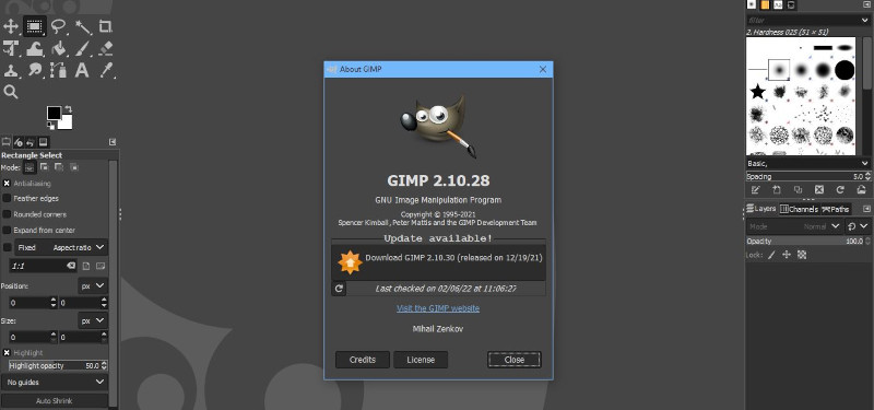
Working with GIMP.
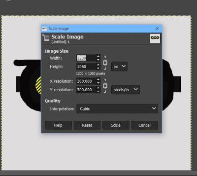
I have already installed and used GIMP before for scaling images. The GIMP interface is shown below.
GIMP Tasks
- Download and install GIMP
- layout and tools in GIMP
- Creating a new project and settings
- Bucket tool / change background color
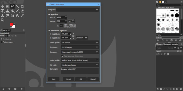
I used the tutorial available at https://www.youtube.com/watch?v=Q8C0LJPpr64 to underatand the basics things that I can work with. I start with, new image project sized at 1200x600px, with other settings such as 300pixels/inch resolution, color space and background color.
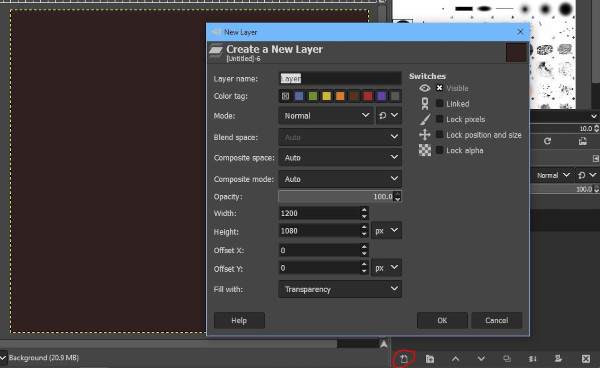
- Create a new layer and working with different layers
- Moving layers
- Adding and editing text
- Creating Rectangles and Elipses, Color fills
- Blending tool
- Exporting the image and saving projects
- Scaling an Image
Working with GIMP - PCB Design to Grey
I tried to work with my PCB design board and create a contrast enhanced board on GIMP. The outcome with tools used is shown below.


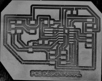
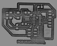
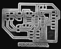
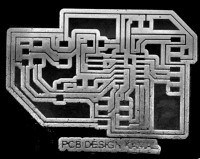
Figure: Image manupulation in sequence 1. Original Image, 2.Image2Gray, 3.Contrast and Brightness change, 4.Erazing edges and Filling, 5. Level Invert 6. Color Enhancement
2D Modelling with GIMP.
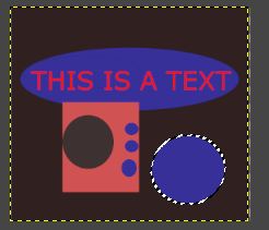
GIMP is an Image manupulation software that works well in editing image files. However, creating graphics with GIMP is a bit different compared to photoshops and Paint tools. GIMP only has select tools and editing tools, therefore we have to make use of the rectangular or elliptical select tools to create shapes, fill with desired colors to make it resemble desired system.
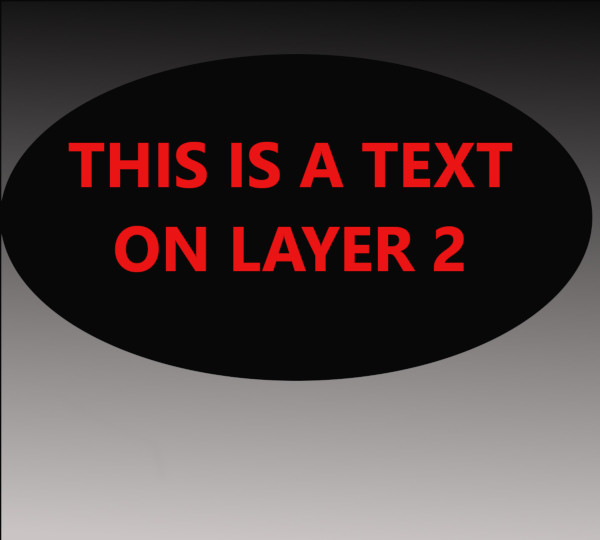
Figure: A random image with shapes, Fill and Text.
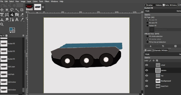
Project 2D Model with GIMP
In order to create a 2D model of my Project with GIMP, I used the path tool and convert path to selection where random shapes and curves are present. Standard shapes are created using rectangular and elliptical selection tool. Layer is a handy tool in GIMP whereby we can create different objects on different layer, edit them separately and merge them in the end.
The shape of the wheel uses standard ellipse shape while all other non standard shape use path tool with path to selection.

The Project File can be downloaded from HERE
Working with Inkscape
Inkscape is yet another powerful image editing and manupulation tool. It works on vector image format and hence the image pixelation is not seen when zoomed in. This effect is shown at the begining of this page.
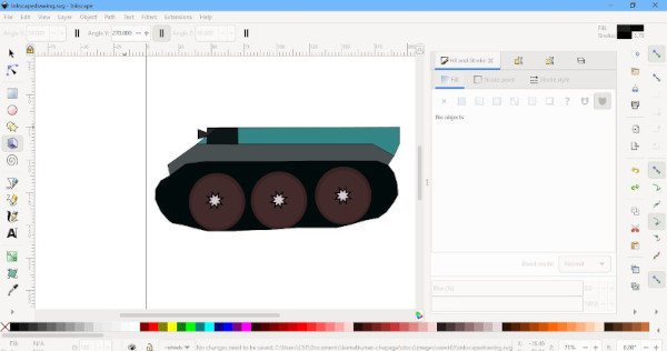
Project 2D Model with Inkscape
Using Inkscape as well, i drew the unscaled 2D model of the project. The figure is shown below. Since, Inkscape uses object and object remain independent, it is easier to work with Inkscape than GIMP for creating and editing object.

The Project File can be downloaded from HERE
Editing colors and formatting of object is similar in both GIMP and Inkscape. However resizing of image is easier in GIMP.
GIMP uses jpg format by default which is lossy over time whereas Inkscape uses png by default and is lossless.
Other 2D Tool
The list below shows some of the things I have learnt in Illustrator:
Illustrator basic:
- mouse control: zoom (alt + wheel control), pan (space + left button drag)
- Interface: Tool panel, control panel, option panel
- Objects: rectangle(+shift : square), elipse (+shift : circle),
- Color control: Stroke / Fill
- Control: (selection tool), click -> select, drag -> move, shift -> change scale with same proportion, Selection tool / Direct selection tool
- Rectangle(practice by drawing house): Change size from number, Round corner
- Elipse: shift + draw -> circle, start point and end point, stroke color, open and close
- Polygons / Star tool
- Pen tool (Bezier line): straight line and curve
- Activate snap (Alt + u)
- Ruler show/hide (Alt + r)
- guide line
- Display mode(Alt + y): Outline, Normal
- Node editing: add node, delete node, separate node, merge node
- Paint brush tool (Free hand): join (control + j)
- Path finder (Object association): Union, Difference
- Group: Group, Ungroup
- Text tool
- Outline
- (Path Effect)
- Color: color pallet, color pick
- Text tool: text along path, Perspective text, font(bauhouse93)
- Layer: forward, backward
- import image: move / transform, set Mask
- Text clip: clip -> mask
- trace image: vectrorize drawing, vectorize logo
3D Modelling
Softwares Used
- TinkerCad
- Fusion 360
TinkerCad Tutorial
For the practice and initial famaliarization, I began working on my previous work on Tinkercad. ThikerCad is a easy to use, online 3D CAD tool that can be used for simple 3D design and 3D printing. The complexity of the design is much lower than other CAD tool however, It provides a simplier and easy to use user interface to design and develop 3D models.
Some of the designs i have practiced include:
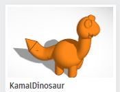
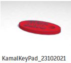
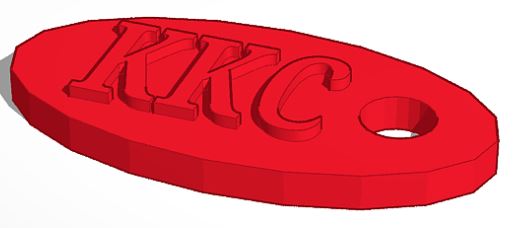
Figure: Practice with Dinosaur and KeyRing Design
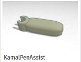
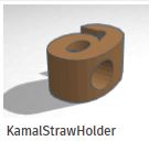
Figure: Practice with Pen Holder and Straw Holder
Tutorial on Fusion 360 (Creating a Car)
- New Project
- File > New Design
- Create Sketch
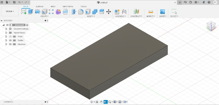
Body of Car
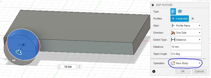
- Create rectangle, Change View and Extrude
- Use Dimensions to change Length, Width and Height of Extrude
Important Mouse Movements
- Scroll to zoom
- Push Mouse Scroll Button to pan
- Shift+Push Scroll to change views
Making Wheel for the Car
- Select side, Create Sketch to make wheel on the body
- Create point and change dimension to create a center point
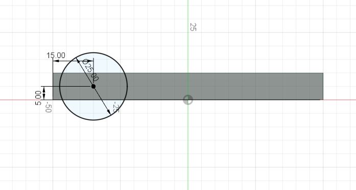
- Create Circle, Extrude to resemble a wheel.
-
Change the property of extrude so that the wheel is not joined to the body for animation.
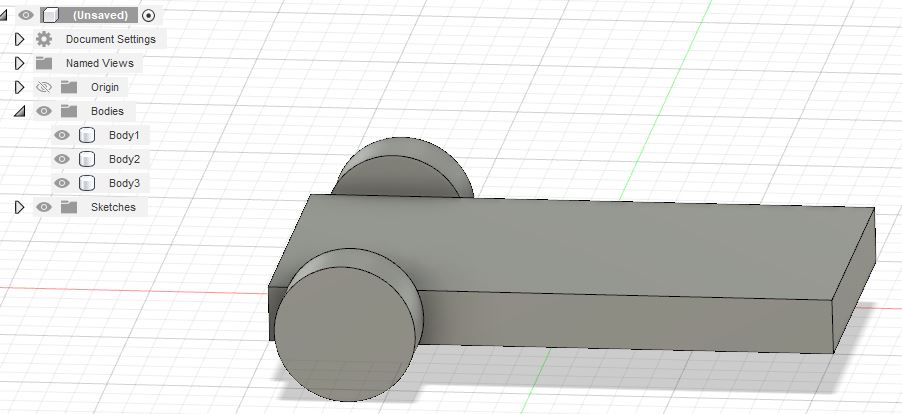
-
Mirror the wheel as body to the other planes to make 4-wheels.
- Create -> Mirror (Select Plane to mirror to.)

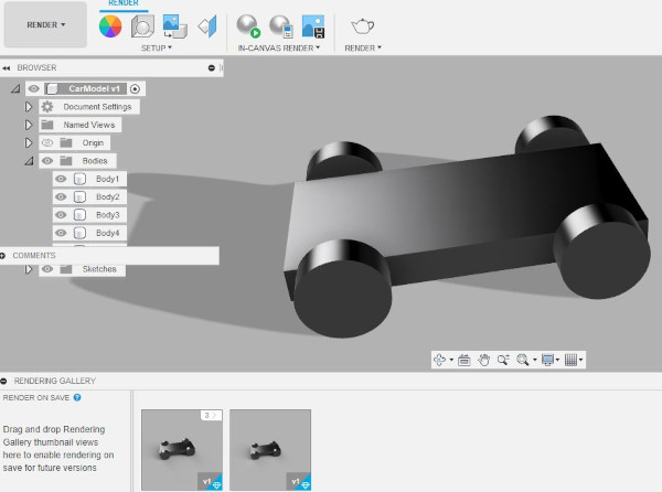
Rendering There are couple of settings we can use for rendering after scene setting. I have used incanvas rendering and rendered on cloud and local. The result is shown below.
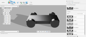
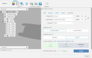
Figure: Rendering Settings
Perspective Animation 1
Perspective Animation 2 (Rotating Wheel) - Change bodies to components - Change wheel shapes to gear.
Fusion 3D Model of Car
Fusion 3D Model for Project
For the 3D Design of my project, I am using Fusion360 software. For the Project, I begin with the design of chain link followed by sprocket and the chassie. I have started by making the individual parts and then to assemble them in the end.
Tank link Design
For the first part I have started with the design of single part of the chain link. The link which is then copied into multiple parts and joined to create the complete link. For the initial stage, i will create individual components and then join it after 3D printing.
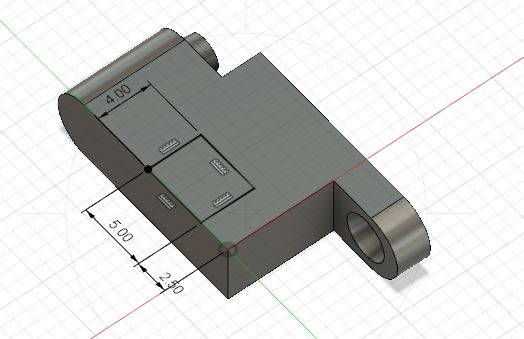
The 3D printable link uses a groove and ridge. This will help in creating a joint while adding flexibility in creating rotation joint.
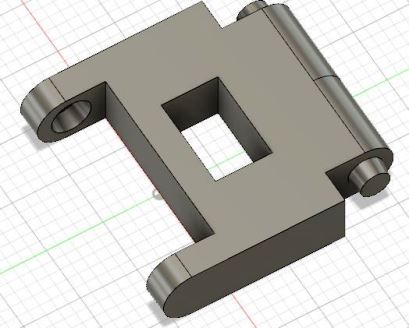

Using the mirroring technique along a plane, I was able to create the mirrors of the individual links along a path that resembles the tank link.

I tried to animate the model in Fusion 360 as well.
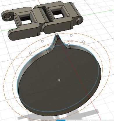
Tank Sprocket Design
The design of Sprocket is a tricky task as the design rule and mathematical relations needs to be known:
Torque or Speed
For a chain and gear system, the size and number of teeth in the gear system determines the torque and speed of the machine. For a tank, we have a single drive sprocket that will be connected directly to the motor and it will determine the torque and speed of the overall drive. Further, the size of the drive system and weight also determine the overall performance.
The torque and soeed have inverse proportionality. Which implies that, increasing the speed would reduce the torque and decreasing the speed would increase the torque.In gear and sprocket system, the ratio of the driving and driven gear/sprocket will determine how the speed and torque changed with the gear ratio. For the current project, will would want the tank to travel in terrains that have more obstacles hence torque is of importance with nominal speed. The system is also controlled and used in smaller areas and hence require lower speed.
Other terms of Interest:
- Pitch Diameter = Arbitary (50mm)
- Radial Pitch = 17mm from the track design
Module = Pitch Diameter / Number of Teeth Let Number of Teeth = 20; Module = 50/20 = 2.5 ;
OR
The formula for the number of teeth is:
N = PD
N = (πD ) / p
Where:
P = Diametral pitch
p = Circular pitch = 17.06mm
N = number of teeth
D = Pitch diameter, Assumed 50mm
Π = 3.14
Therefore: N = 3.14 x 50 /17.06
             = 9.2  (Fractional Value of N not desirable)

Using Reverse Method to determine D:
D = N*p/3.14
    Let N = 12;
D  = 10*17.06/3.14 =  54.33mm

And Module M = P/3.14159 = 17.06/3.14159 = 5.4303
D (Pitch Diameter) = Pitch /(sin(180/N))
                   = 17.06/sin(18) = 55.20731

I created a number of concentric circles to give me the outer diameter, pitch diameter and inner diameter. On this, I create arcs with tangent constraints and make use of mirror to create a sprocket teeth.
The Sprocket teeth are also aligned with the track previously designed such that they would aligh properly and the teeth fit to the link. With one of the teeth designed, I make use of the pattern command to create a circular pattern of the teeth around the pitch diameter. This way there will be ten sets of identical teeths around the pitch diameter and with a desired pitch.

Further i have created some design and holes on the sprocked so that it can be fixed using a shaft. Further design will be conducted on the sprocked based on the need of the project.
Sprocket Design Fusion360
Tank Roller Design
The rollers for the design is necessary to hold the chain link properly in place along the base of the tank. This will have smaller dimensions compared to the sprocket. At this point, I am designing rollers of dimension 3cm each and a total of four rollers will be placed along the link.
Tank Chassis Design
For the current project, the size of the tank is discussed with a width of 120mm and length of 260mm. This design will not be printed by the 3D printing hardware in our lab and therefore needs to be fabricated in parts. I am creating two part chassie
Chassis Design Fusion360
Combining All Design
Project Files
- GIMP Project File: GIMP 2D Model Project
- GIMP Project File: GIMP Random Project
- Inkscape Project File: Inkscape 2D Model Project
- TinkerCad Project File: TinkerCad Project File
- Fusion Project File: Fusion 3D Model Tutorial
- Project 3D File: Fusion 3D Model Project