16. Applications and Implications
This week I worked on defining my final project and answering questions related to the Final Project and its application. The assignemtn for the week is as follows:
Individual Assignment:
- Propose a final project masterpiece that integrates the range of units covered, answering:
- What will it do?
- Who’s done what beforehand?
- What will you design?
- What materials and components will be used?
- Where will come from?
- How much will they cost?
- What parts and systems will be made?
- What processes will be used?
- What questions need to be answered?
- How will it be evaluated?
- Your project should incorporate:
- 2D and 3D design,additive and subtractive fabrication processes,
- Electronics design and production,
- Embedded microcontroller interfacing and programming,system integration and packaging
- Where possible, you should make rather than buy the parts of your project
- Projects can be separate or joint, but need to show individual mastery of the skills, and be independently operable
What will it do?
Disaster are unpredictable and happens regularly in different part of the world. Few of the common disasters to hit Bhutan are Fire, Landslide, Earthquake and Flood. During such time, people have very less time to make decision and maynot be able to run. This would cause them to be trapped inside the houses. It is very risky for people to go into the building directly and look for survivors as there is chances of another mishap. Therefore, current practice to use excavation to remove the collapsed parts in layer and look for bodies or survivors. However, If we can have a tiny eye that we can send into the collapsed house or any structure before excavation, we can reduce the risk of causing damage to the surviving individuals. Further, we can increase the survival rate of critically injured people if we can embed with suitable sensor to sense presence of life under the rubble.
In my final project, I planned to build a robot that resembles a tank which can be applicable in disaster areas. The robot will be able to menuvour through different obstacles and send feedback to the user in the form of video feed, obstacles in the path using Ultrasonic sensor and motion detection using PIR sensor. The
Who’s done what beforehand?
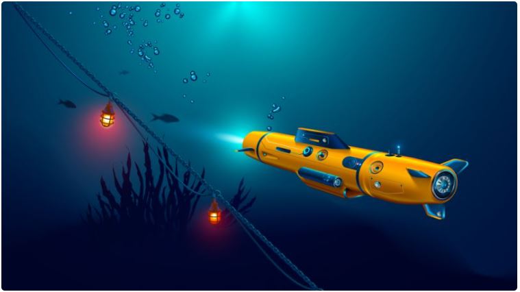
There are a lot of advanced Rescue robots in market that are being used for many different applications including Water, Land and Air. The link at rescue-robots summarizes a dozen of rescue robots in use in the field. The rescue robots are in the forms as dictated by the applications. Rescue robots for water such as the one shown in the image below resembles a submarine and can be used to rescue under water.
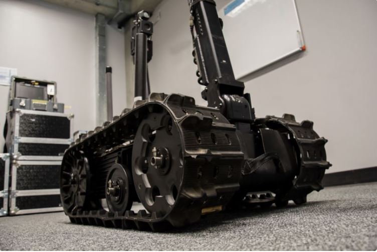
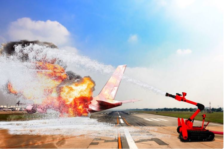
On land, there are a number of rescue robots that resembles a tank for search and rescue in disaster areas or robots that can pump water and can be used in fire fighting or rescuing where people cannot access. The example images taken from the aforementioned webiste is shown below:
Land Rescue
Fire Rescue
In FabAcademy, I search with the tag “RESCUE” and “ROBOT” and found few instances of the terms however there was no one who have worked in building a rescue robot in the course. However, One student in year 2018 Aby-Michael had proposed to build a search and rescue robot that resembles my project, however it was dropped and he worked on a bluetooth controlled toy car with ultrasonic sensor for obstacle detection. The main reason he dropped the project was in consultation with Neil, the projects had many components and would have been a combined project. In my review with Neil, he said that it can be taken up but need to look at what others had done before me and to build onto that. My project consists of the following.
- ESP32 camera module for Camera feedback.
- Ultrasonic sensor for obstacle detection.
- Robot that resembles a tank that can menuvour in different terrains.
- PIR sensor for motion detection
- Remote control using Mobile application or webview application.
What will you design?
There are three main components that I will work on.
- Design of Controller board.
I am making use of an ESP32 camera module as controller board for the robot. The ESP board will connect to the WiFi network and can be controlled throuugh webview. The controller board sits on top of other circuits mainly power supply module containing regulators and motor driver. The board also contains connecter headers for PIR and Ultrasonic sensor.
At this stage, the The design of the controller board and other circuits have been completed and tested. The details of the same can be found in the Project section Electronics in Project as well.
- The chassis of the robot will be either 3D printed or laser cut
The 3D design of the chassis has been completed and ready for 3D Printing. At this stage, I am doing the first test on the system using chassis built using laser Cut board chassis. The chassis design for the laser cut is made in 2D in Fusion360. At this stage the Laser Cutting of the chassis is completed and the first round of testing is under way. The images and videos below shows the first testing of the robot with laser cut chassis.
- Wheel and Sprocket Design.
The wheel and sprocket including chain link is designed in fusion360. They are printed using 3D printer. The first print of the components including the battery casing is shown in the project section CAD Design and 3D Printing:
All the above components will be assembled for the first test and if the system works well, then I will move on to improve the system with better materials and casings. The primary work on Laser Printing and assembly is shown below:
What materials and components will be used?
Materials Required and Pricing
| sl.no | Description | Qty | Price | Total |
|---|---|---|---|---|
| 1 | ESP32 Cam module | 1 | Nu.900 | Nu.900 |
| 2 | Camera Module | 1 | - | - |
| 3 | Ultrasonic Sensors | 2 | Nu.150 | Nu.300 |
| 4 | DC Motors | 2 | Nu.300 | Nu.600 |
| 5 | Bearings | 5 | Nu.300 | Nu.300 |
| 6 | PIR Sensor | 2 | Nu.100 | Nu.200 |
| 7 | Regulator | 2 | Nu.100 | Nu.200 |
| 8 | 3D Printing Parts | 5 | Nu.1000 (Estimate) | |
| TOTAL | - | Nu.3500 (USD45) |
Where will come from?
Most of the parts required are bought through our instructor from India or Japan. Components required for the fabrication of the motor control and Input/Output boards are available in the lab. The components including PCB boards and SMD components like motor driver, voltage reguulator, Resistors and Capacitors, LEDs are available in the lab inventory. I have made use of these components in the board design.
How much will they cost?
The costing of the components are shown below. The total cost of components is around USD50.
Materials Required and Pricing
| sl.no | Description | Qty | Price | Total |
|---|---|---|---|---|
| 1 | ESP32 Cam module | 1 | Nu.900 | Nu.900 |
| 2 | Camera Module | 1 | - | - |
| 3 | Ultrasonic Sensors | 2 | Nu.150 | Nu.300 |
| 4 | DC Motors | 2 | Nu.300 | Nu.600 |
| 5 | Bearings | 5 | Nu.300 | Nu.300 |
| 6 | PIR Sensor | 2 | Nu.100 | Nu.200 |
| 7 | Regulator | 2 | Nu.100 | Nu.200 |
| 8 | 3D Printing Parts | 5 | Nu.1000 (Estimate) | |
| TOTAL | - | Nu.3500 (USD45) |
What parts and systems will be made?
The Parts and systems that I am fabricating are:
1. Motor control circuit with motor driver.
2. Chassis for the robot which will be 3D printed.
3. Casing for the robot which will be Laser Cut.
4. The Sprocket of the robot is designed in Fusion360 and 3D printed.
5. The Chain Link for the robot is designed in Fusion360 and will be 3D Printed.
What processes will be used?
-
PCB design and Milling First I make use of SRM and Soldering to build the Final Project controller board on which will be the ESP32 Camera Module which controls the motor driver which is also in the same board. The input and output devices are connected to the board through I/O ports of the controller board. The detail of the same is shown in Project Section Electronics in Project
-
Laser Cutting Then I design the 3D model of the chassis and the sprocket. First testing is done using 2D design in Fusin360 and cut in Laser Printer. The detail of the same is updated in the project section Chassis design and Laser Cut
-
3D Printing Some of the components inclusing casing for battery are already 3D Printed at this stage. I will also 3D print the sprocket wheel and othere accessories. Further the chain link will be 3D printed. The robot itself is bigger in size and hence takes long time to 3D print. Therefore for the initial testing, I will make use of laser cutting of board and Acrylic to design the chassis of the robot and if the reults are not satisfactory, I will 3D print the whole chassis. The details of 3D printing can be found in the project page at: CAD Design and 3D Printing:
-
Embedded Programming The controller board will be programmed to connect to the WiFi network and control the I/O devices. The controller also communicates with the application that remotely controls the motion of the motor. The details can be found at the project page at: Embedded Programming:
What questions need to be answered?
The main questions that need to be answered are:
- Electronics Design
I have looked around and researched a bit on what electronics is relevent and available for my project. There were a number of options that i could make use of that included different controllers and communication systems. Through these study i found that for my application, I can make use of the ESP camera module that has both the controller and the camera installed in it. Further, the ESP camera module can connect to both bluetooth and wifi and can be remotely controlled. Therefore, I made use of the ESP camera module.
Then i moved on to selecting the motors that i can make use of. The options available were DC motors and stepper motor. I could make use of stepper motor to precisely control the speed and rotation but the torque of DC motors with inbuilt gears were superior. Therefore, I choose to use 12V DC motor that has good torque to carry forward the robot.
With the motors selected, I moved on to selecting the drivers that i would be needing. Through the fab inventory, I came accross the 49series motor driver that works well with 12V suppply and can supply the required current to the motors.
Further, There were requirement of a couple of power supply voltages to the system. The ESP camera module requires a 3.3V, while the motor uses 12Volts. I designed the power supply system that has voltages of 12V, 5V and 3.3Volts. This way I will be able to power all the devices through a single power supply. however, the requirement of the current is very high due to the DC motors. Therefore, I also need to design a powerbank with sufficiently large current delivering capability. We had 9V, 900mAh batteries in lab so I make a series parallel connection of four batteries to give me a voltage of 18V and power of 3600mAh. This should last for few hours when all the circuits and motor run continuousy.
- Chassis Design.
There are a couple of options available for me to design the chassis. The software I make use of is Fusion360 to design both 2D and 3D models of the chassis. Further, the material I can make use of are board, Acrylic and PLA 3D print. Initially, I have made use of 2D models to design the chassis with board and then i would port the same to Acrylic design. I will also design a couple of accessories including battery casing, roller holders and wheel sprocket using 3D printing. If all goes as planned, I would export all the design into 3D and create a 3D printed model of the same.
How will it be evaluated?
My main aim of the Project in the Fab Academy is to build a robot that can be remotely controlled while providing the live video feed to the application.
| Sl.no | Tasks | Evaluation |
|---|---|---|
| 1 | Design&Produce a casing for the electronic | It should hold the electronic and fit the battery |
| 2 | Agility | The robot should be able to properly menuvour through different obstacles |
| 3 | Electronics Production | Design and produce a board that can properly run the required function |
| 4 | Interfacting | Create application that can effectively communicate with the controller and produce desired response |
| 5 | Obstacle Detection | Properly detect obstacle and relay to Application |
Project Plan and Tracking System
The status of the project work can be found at the project site: Final Project.
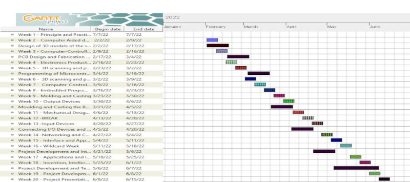
The initial plan developed in Week 1 can be found in Week 1 - Project Management. This plan include the project in parallel with the weekly assignments as shown below:
The status of the project as of week 16 is summarized in the table below.
What tasks have been completed, and what tasks remain?
| Sl.no | Tasks | Weeks | Status |
|---|---|---|---|
| 1 | Electronics Design | Practice in Week 6 | Completed as of Week 16 |
| 2 | Electronics Production | Practice in Week 4 | Completed as of Week 16 |
| 3 | 2D Design and Fabrication | Practice in Week 2 | Final Design and Cut in week 16 |
| 4 | 3D Design and Printing | Practice in Week 5 | Final Design completed and Printing in week 16 |
| 5 | Embedded Programming | Practice in week 8 | Complete programming and Testing in week 17 |
| 6 | Networking and Interfacing | Practice in week 13 | Complete programming and Testing in week 17 |
| 7 | System Integration and Assembly | To be complete in week 17-18 | |
| 8 | Final Project Development | To be completed in week 17-19 | |
| 9 | Testing and Validation | To complete after week 17 and before final Presentation | |
| 10 | Preparation of Slide and Video | To complete after week 17 and before final Presentation | |
| 11 | Final Outcome/Scope | A robot that is remotely controlled and that sends data to user in the form of camera video stream, Obstacle Distance and Motion Detection in the vicinity |
What’s working? what’s not?
At this stage, Individual component testings has been completed. Most of the systems and assemblies are functioning as expected:
- The controller connects to the WiFi network and broadcasts live video stream and can be controlled through an application with a small delay.
- The controller and application is able to control the output device mainly the motor through a motor driver and additional power supply (12V robot battery is used to power the motor seperately)
- The input devices used are PIR and Ultrasonic sensors and can correctly send signal to the controller triggering events on reaching threshold.
- The ESP32 controller gets reset from time to time when connected to a powersupply system with regulated voltage of 5V powered through a 9V 300mAh battery. The same is also occuring when it is powered through the power supply unit and 12V 3000mAh battery. The power supply to the board is currently 2 pin DC input through a regulator connected to the type B 5V input of ESP Wrover board (Need to check with other methods to eliminate the resetting of board)
- The two wheels are not in perfect sync and turns at starting of the robot. (Need to find the source of problem and get solution)
- The range of the WiFi PCB antenna embedded on the ESP32 module is low and need to be increased for better through put and better video streaming.