4. Electronics Production
This week we had a group and individual assignment to work on Electronics production. The folowing was the group assignment and individual assignments:
Group Assignment:
- Characterize the design rules for your in-house PCB production process
- Extra credit: send a PCB out to a board house
The details of the group assignment is available at: Group Assignment Week 4
Individual Assignment:
- Make an in-circuit programmer that includes a microcontroller:
- Extra credit: customize the design
- Mill and stuff the PCB
- Test it to verify that it works
- Extra credit: try other PCB processes
Starting Point
With the group assignments completed, I began by downloading the png file for the in-circuit programmer. The png file for the programmer was downloaded from http://fab.cba.mit.edu/classes/863.16/doc/projects/ftsmin/fts_mini_traces.png and http://fab.cba.mit.edu/classes/863.16/doc/projects/ftsmin/fts_mini_cut.png


The two files were first downloaded to the PC and used to generate RML file using mods.
PNG to RML
Initially, the png file for both the trace and cut are downloaded and copied to the PC connected to SRM20 and containing the V-Panel software. Since the png file has to be converted to machine readable format I made use of online version of MIT mods http://mods.cba.mit.edu/
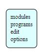
In MIT mods there are four options namely - Modules - Programs - Edit - Options
For my case I first go to Program >> open server Program. Scroll down and under SRM20 choose PCB PNG.

This takes me to the page where I can choose the png file. For each of the traces and cut, I have to generate individual .rml file and send it to the v-panel and inturn to the SRM20 milling machine.

We load the png files individually and generate the rml file.
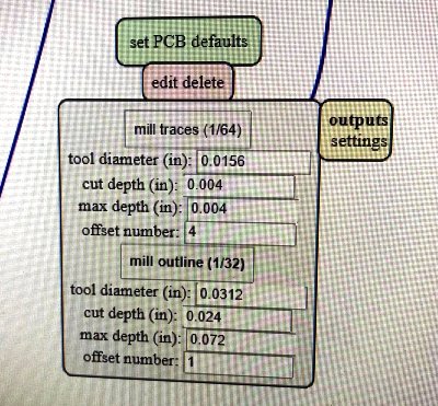
Once the png file is loaded, we select the endmill size based on the function we want to perform. For the line trace we use a 1/64mm endmill while we make use of 1/32mm endmill for cutting the board. Under the Set PCB function, we can also change the settings for Cut Depth, Max Depth and offset.
The cutdepth in the rml file with set the depth at which the board is going to be cut. These values are also dependent on wether we are working with the trace or cut. The cutdepth of the trace is proportional to the thickness of the copper so that the cut removes the copper only. However, the cut depth of the border should be such that the the PCB board thickness is considered. This way the board is successfully cut with minimal cut to the sacrificial layer.
Cut Depth Settings for Trace
We make use of the following settings:
- Tool Diameter for Trace: 0.0156inch
- Cut Depth : 0.004inch
- Max Depth : 0.004inch.
Due to some allignment issues in the bed of the SRM20, we had to change the cut depth a couple of times however we had changed it to the settings below to get proper trace. These settings had to be changed everytime we change the PCB board because of differences in setting the board on the sacrificial layer.
- Tool Diameter for Trace: 0.0156inch
- Cut Depth : 0.008inch
- Max Depth : 0.008inch.
- Offset: 4.
Cut Depth Settings for Cut
- Tool Diameter for Trace: 0.0312inch
- Cut Depth : 0.024inch
- Max Depth : 0.072inch.
- Offset: 1.
The value of offset determines the amount of copper that is removed. If large value of offset is set more copper is removed from the path adjecent a trace. It also determines the clearance between the trace and the nearest conducting layer. Care should be taken such that the trace donot create design error due to shorting of conducting layer. Therefore a sufficient spacing is required to be maintained.
Offset: The offset for the case of trace was set at 4 while the offset for cut is set at 1.
Then we also need to remove the output and create a saving point for the rml file and set the origin to 0,0,0. The saving point can be achieved by first deleting the default web socket device and replacing it with a saving point module.

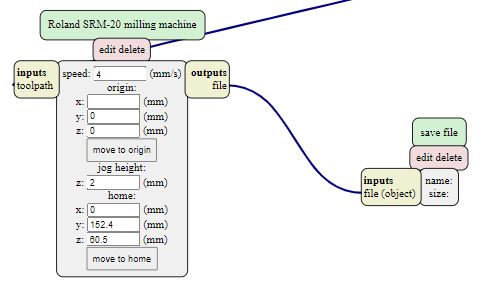
The save module can be inserted from rightclick > module > open server module > save under file. Now, As we press calculate, the rml files are saved in downloads folder while we can also view the cut trace path. We can copy the file to suitable location or keep it in the same location.


Trace RML File: Trace RML File
Cut RML File: Cut RML File
RML to PCB Milling
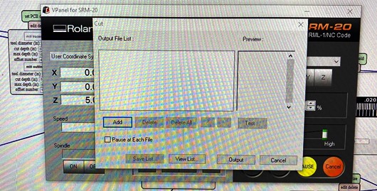
With the files saved appropriately, We paste the PCB board as required on the bed of the machine using double sided tape and sacrificial layer. Then, we open the v-panel for SRM20. V-panel for SRM20 is the control panel available as a software. It communicates with the machine through USB interface and controls various options.
Specifications of SRM20
- Taken from: https://purpleplatypus.com/products/roland-3d-mills/monofab-srm-20/
Workpiece Table Size: 9.14 (X) × 6.17 (Y) in.
Operating Speed:
6-1800 mm/min
(0.24079.87 inch/min)
X,Y,Z Operation Strokes:
203.2(X) × 152.4(Y) × 60.5(Z) in.
Mechanical Resolution:
0.000998 mm/step
Machine Dimensions:
17.76(W) × 16.80(D) × 16.78(H) in.

We can control the position of spindle in three directions of X,Y and Z and set the origin points for the machine to work from. We can add the rml file and start/stop the machine. Further we will be able to visuallize the status of the machine in terms of the spindle position and speed to operation and speed in rpm of the spindle and endmill.
So, we first change the position of the spindle such that it is located at the desire XY position. Then we change the endmill based on our requirement. There are different types of endmills. In our case we are making use of Regular 2-Flute Square end 30degree Halix
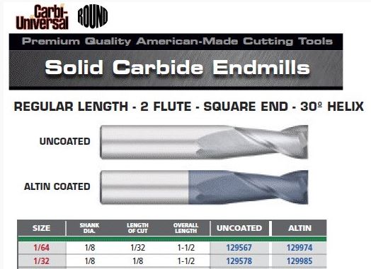
We first change the endmill to 1/64mm endmill for cutting the traces.


NOTE
- The SRM20 has a door open sensor that will not allow for the spindle to move if it detects the door is open.
- The SRM20 will also pause the milling process if the door open during operation.

With the endmill changed, we have to set the origin point. This a accomplished by first changing the position of the spindle and taling it to the desired position. Pressing set origin point XY sets that point as origin and X and Y position will change to 0,0. Then we slowly lower the spindle (Change Z) such that the tip of endmill nearly touches the PCB board. We use gravity method for zeroing the Z which is when we loosen the screw and allow the endmill to drop to the PCB board with gravity. We tighten the endmill firmly and cloase the machine door.

The we load the rml file to the V-panel by pressing the cut button and open file to load, then we give it as output to the milling machine.
Cut Settings
- Step speed of the trace:240mm/min. We set the step speed at 100%
- Spindle speed: 9000RPM , We set the spindle speed at maximum and the speed reaches above 9000rpm for the SRM20.
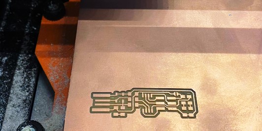
The milling machine automatically starts milling and will stop at the end of its cycle. As the machine stops after milling the traces, we check visually to see if the traces are correctly milled.
Further, we make sure that the traces are clean and precise. The next step follows as before where we create rml file for the cut. We change the endmill size to 1/32 mm and load it to the V-Panel and send to mill.
Cut after Trace
- We should not change the preset XY Position of V-Panel, Changing it will make us loose previous setting.
- We only change the Z-direction from V-Panel to enable us to change the endmill to 1/32mm for cutting.
- We go to the home point of XY automatically and use zeroing method to change the Z-Axis.

Cut Depth setting
- Sometimes the default cut depth donot give the desired result maybe due to misallignment of the PCB board on the bed
- We can change the cut depth of the machine from the mods allowing us to cut deeper.
Once the cut is completed, we have to remove the cut piece from the board. Since the board is pasted using double sided tape, care should be taken so that the damage to the board is minimum.
Finally, I was able to successfully mill the given trace and cut. The next step is to gather the components and solder them to the board.
Soldering Components
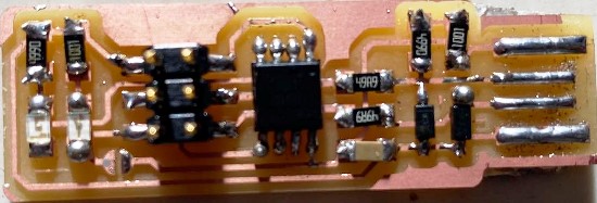
The components required to be soldered are:
- 1x ATtiny45 or ATtiny85
- 2x 1kΩ resistors
- 2x 499Ω resistors
- 2x 49Ω resistors
- 2x 3.3v zener diodes
- 1x red LED
- 1x green LED
- 1x 100nF capacitor
- 1x 2x3 pin header

We collect the components from the inventory. Then we proceed to solder the components


Care should be taken while soldering because the components are rather small and a small mistake could lead to redoing the entire process from milling. Using a multimeter to check the continuity regularly helps in determining the errors earlier. Finally, I was successfully able to solder all the components properly on the board. Once all the components are connected, we move to programming and testing the board.
Testing the Board
The board is to be programmed using ISP Programmer. We are using Atmel ICE Programmer. The programmer and the board needs to be alligned using 2x3 connector for programming to be successful.

Once the board and programmer are connected, we connect both to the USB port on our PC.

The Red LED will glow indicating that the power is working.
The software used to program the board is AVR programmer. I have used Ubuntu OS to program the board. The software is downloaded from: http://fab.cba.mit.edu/classes/863.16/doc/projects/ftsmin/index.html

Once the file is downloaded, we go to the folder, extract the file and go into the folder.
cd fts_fts_firmware_bdm_v1
Inside the folder we run makefile. First we edit the makefile such that the programmer is changed to atmelice_isp

Then we run the make in the terminal from the AVR folder.
make flash


In the first run, I had error in programming the board. I tested each connections using multimeter but still the error persisted. I then went back to soldering and made the solder joints bigger for some of the controller pins and pin header. Finally I was successful in programming.

make fuses
Once the flashing is completed, we run the make fuse command

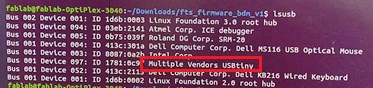
Then we run the list usb command to see if the usb reads our board. If the Attiny is listed then it implies that the board is programmed.
lsusb
Next step is to blow the reset pin to make the programmer pin into IO pin, we run the command
make rstdisbl

Finally, we remove the jumper connection and are done with building a In-circuit Programmer.

Files
Trace RML File: RML File of Trace
Cut RML File: RML File of Cut