3. Computer Controlled Cutting
This week we had a group assignment and individual assignment to work on vinyl cutter and laser cutter. The folowing were the assignments:
Group Assignment:
- Characterize your lasercutter’s focus, power, speed, rate, kerf, joint clearance and types
Individual Assignment:
- Cut something on the vinylcutter
- Design, lasercut, and document a parametric construction kit accounting for the lasercutter kerf, which can be assembled in multiple ways, and for extra credit include elements that aren’t flat
Group Assignment
Characterize your lasercutter’s focus, power, speed, rate, kerf, joint clearance and types
The detail of the Group Assignment is avilable HERE and HERE
Individual Assignment
Image to Vector in Inkscape
I am using the tutorial and approach used in https://blog.wplauncher.com/how-to-vectorize-an-image-in-inkscape/ and https://www.youtube.com/watch?v=10m_2bPXa1s to convert an image to vector. The software i am using for this assignment is Inkscape. I have also made use of Illustrator to practice with.
First I used the national bird of Bhutan Raven to create a vector image. In inkscape, I make use of two tools. First is image to path tool which automatically creates the path from the image and second is to manually create the path and vectorize them. Prior to that, I have also used GIMP software to change the contrast of the image and change color to black and white. This improves the path that can be traced by inkscape.
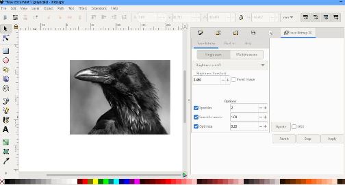
Figure: Creating trace Path in Inkscape.
Vector Images
The vector images created for Raven is shown below:
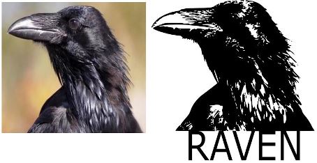
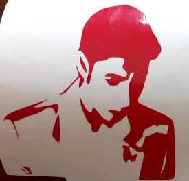
Then I made use of an arbitraty image shown below for vectorization. The image and vectors are shown below.

Figure: Vetorized image for Vinyl Cutting
After the image has been vectorize, it is saved as plain svg file format and import in EasyCut studio for printing.
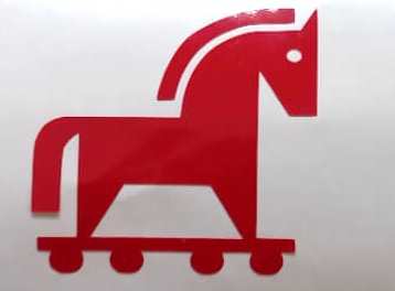
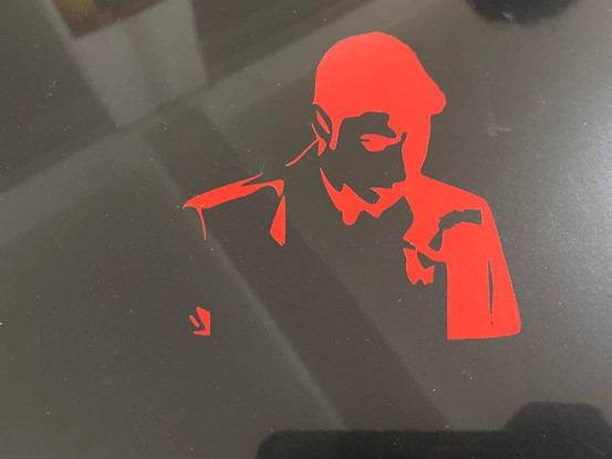
With feedback from regional instructors, I realized that the Raven Image that i have vectorized for Vinyl cutting would be much of a trouble to remove the tiny spaces therefore i have decided to simplify the image for vinyl cutting. Therefore, I created a logo using inkscape. The logo is going to be used for my project.

CRAWLER: The Rescue Robot
Working with Vinyl Cutter
Vinyl Cutter Details
The vinyl cutter at our lab is the Roland CAMM-1 GS-24.
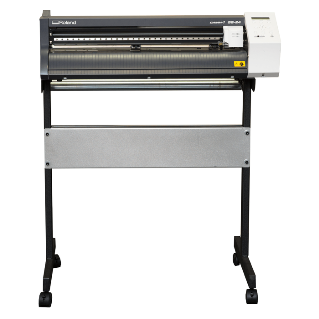
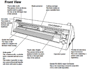

Figure: Image of Roland Cam and labelled diagram taken from Online Portals https://fabacademy.org/2018/docs/FabAcademy-Tutorials
The Vinyl cutter comes with 3 type of cutting blades, each with different angle as shown below.
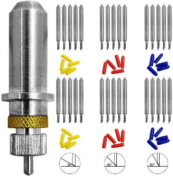
Starting and Working with Vinyl Cutter
- First the vinyl cutter was started on. The cutting carriage goes to its home point at the Right Hand Side. Once started, we set the origin to the point of interest (Press Origin for 3 Second). There are three markers on the vinyl cutter origin point (Left End) with white mark. The cutting carriage is aligned to the markers. We then select the printing material type to rool or sheet.
- There were also three types of cutting blades based on angle on inclination of 30, 45 and 60 degrees.
- There are also two other settings of Power and Speed.
- The rule of thumb is to use High Power, Lower Speed and larger angle of inclination for Harder Materials like Copper and Low Power, Higher speed and lower angle of inclination for softer materials (Vinyl)
- We load the vinyl material to the roller and place it such that it is aligned for cutting.
Using the vinyl printer and a vector image created with image and inkscape, I tried to print on the vinyl cutter and create a sticker.

Figure: Vetorized image imported to EasyCut Studio
Then I imported the file to the Easy Cut studio software, resize the graphics to the desired size and cut the design with default settings. For the current case we make use of the following settings:
- Cutting Force 30 gF
- Speed 20cm/sec
- Blade Cutter with an cutting angle of 45degree.
The output from the vinyl cutter is cut to desired size and I begin weeding the extra materials around and within the graphics. I made use of scissors, knife and tweezers and made sure that the tiny pieces are not altered.
Once the weeding is completed, the required materials should remain on the surface.
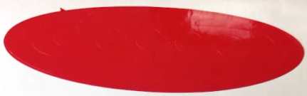
The first print

The image did print well but during weeding process, the smaller pieces didnot stay. Therefore, I had to print the file again.

The materials are to be transferred to surface (where the graphics is to be made) using a tape. Since the tape has more glue, I first use a cloth surface to remove some glue and then paste the tape to cover the entire material that are to be transferred.
Removing the tape slowly allows the design graphics to stick to the tape. The tape is inturn pasted on the surface. Then I slowly remove the tape such that the graphics material sticks and remains on the surface.
Print on Laptop
Print on my Laser Cut Parametric Fit Design
Print on my Laser Cut Parametric Fit Design
Working with Laser Cutter
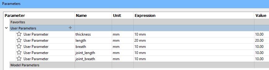
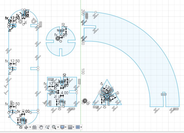
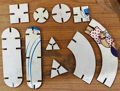
For the individual assignment, I have worked on a couple of shapes that i can use to assemble and create different objects. I have made use of five shapes in total on fusion360. The shapes are shown below. I have used a parametric design to set the size of the shapes and size of the slots.

For Printing in Laser Printer, we first export the design files in .dxf format. The file is then imported in CoralDraw software. The coral draw software is connected to the machine. The size of the printer is 609.6x304.8. That is set in the printing properties.
On the Printer itself, we have to first set the home. To do so, on the control panel we disable the XY movement of the printer. With it disabled, change the point of the printer such that the printing starts from that point. Then with XY disabled it is set to home. Then we give the print command from CoralDraw software with auto focus.
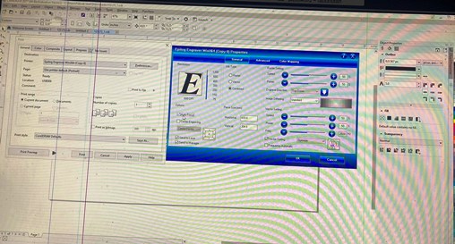
We also refer to the appendix of the Epilog Laser Printer manual for the settings of power and speed for different materials.
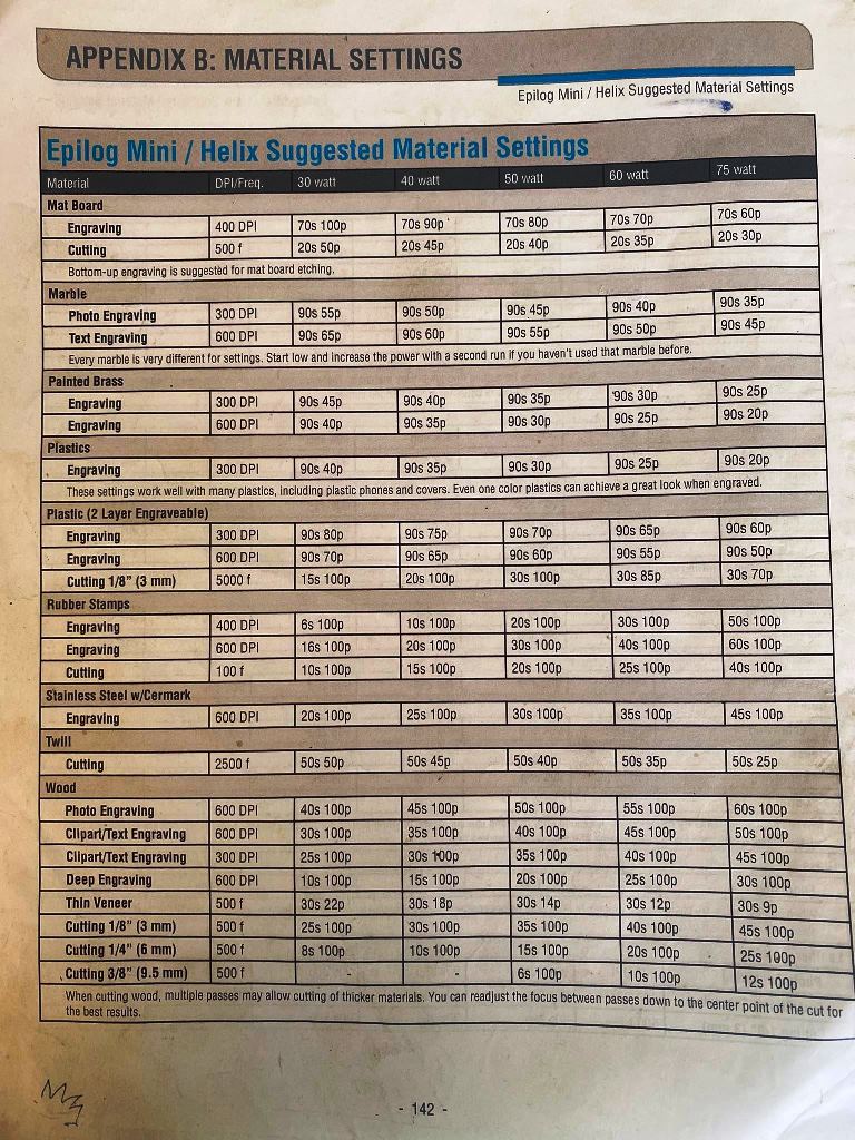
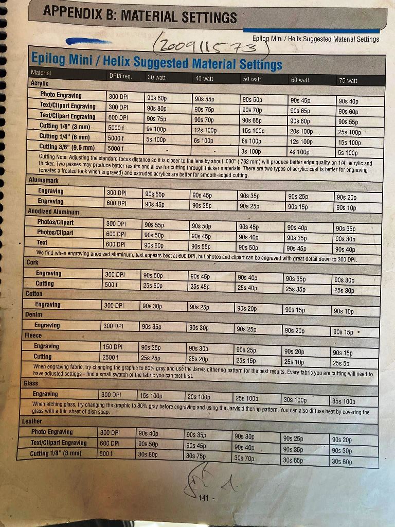
Power and Speed Settings:
From the group assignments available HERE, we determined the suitable power and speed to effeciently cut the board. The cardboard that we are making use of is: 4mm
Settings
- Power : 70% to 80% The higher the power, more materials around the slot is cut, Kerf increases.
- Speed : 20 to 30% Lowering the speed and Power improves the cut but not beyond 60% as it won’t cut the material entirely.
- Frequency: 2500Hz
- Focus: Auto
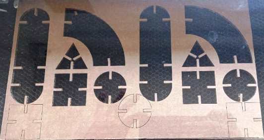
First Laser Print
The first print of the shapes were successful but the scale was bit off and the size of the shapes were larger than expected. It was associated to the different cardboards in use in the lab. Initially, I had designed for 4mm thick cardbord but the board available then was smaller.
After I got the 4mm cardboard, I proceeded to print with the design and got better results.
Major Mistake and Solution (Git and Video Files)
- I added a video of the working of the laser cutter in the project and tried to push
- The total file size exceeded 10Mb, but since it was already committed the push was not working
- I had to do a soft reset of the git commit to remove the last commit.
- The size was still showing beyond 10Mb
- Then i did a
git gcto clean the git folder which improved size and i could then commit and push - Took a while of google and instructor’s help to get to the solution
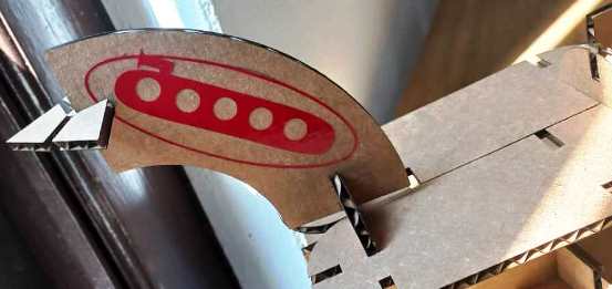
Final Assembly of Press Fit.
Final Print was assebmled to produce a desired shape. A sticker was also created and added to the shape from the vinyl cutter assignment.
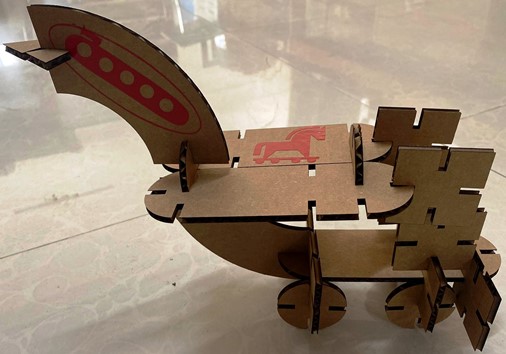
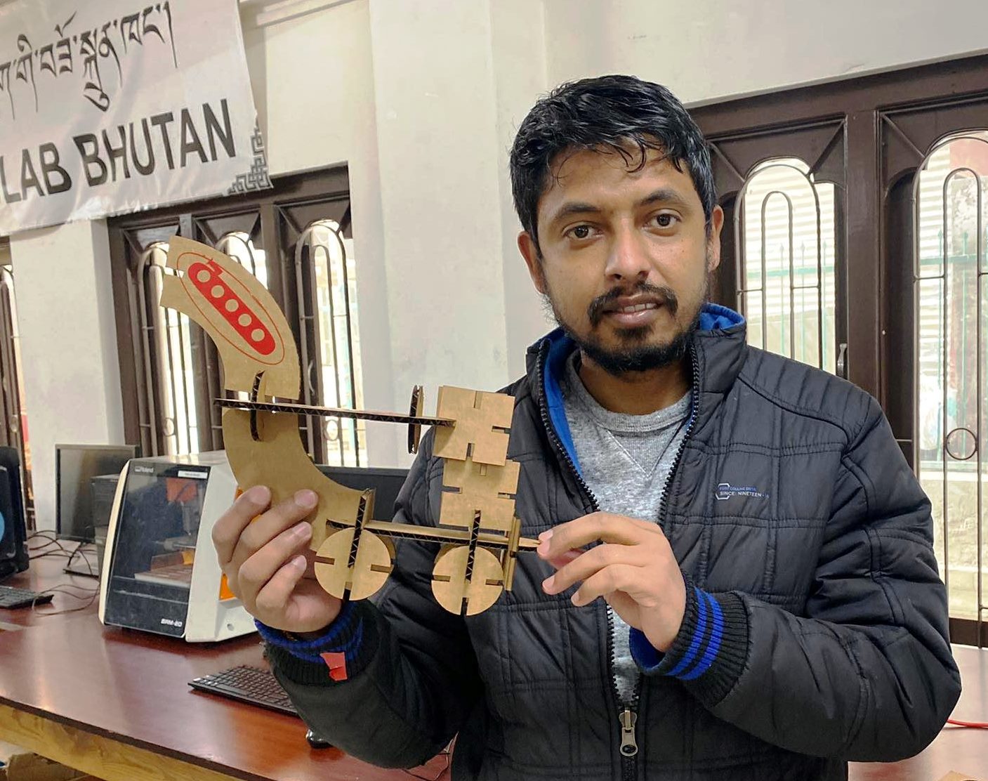
WHAT DOES IT LOOK LIKE ??
Design Files
Inkscape File Raven: HERE
Inkscape File Photo: Inkscape Vector File
Inkscape File Logo: Inkscape Vector File
Parametric Design File: Parametric Design File