Task to be carried out this week
Action Plan
| Date | Work Allocation |
| 9th Feburary | Prof. Neil's Lecture |
| 10th February | Make a logo design for vinyl cutting |
| 11th February | Start making the parametric construction kit |
| 12th February | Continue with parametric design |
| 13th February | Learn the machine specification for the vinyl cutter and the laser cutter |
| 14th February | Cut the logo design using vinyl cutter and the parametric design using the laser cutter |
| 15th February | Documenting the weeks assignment |
Vinyl Cutter
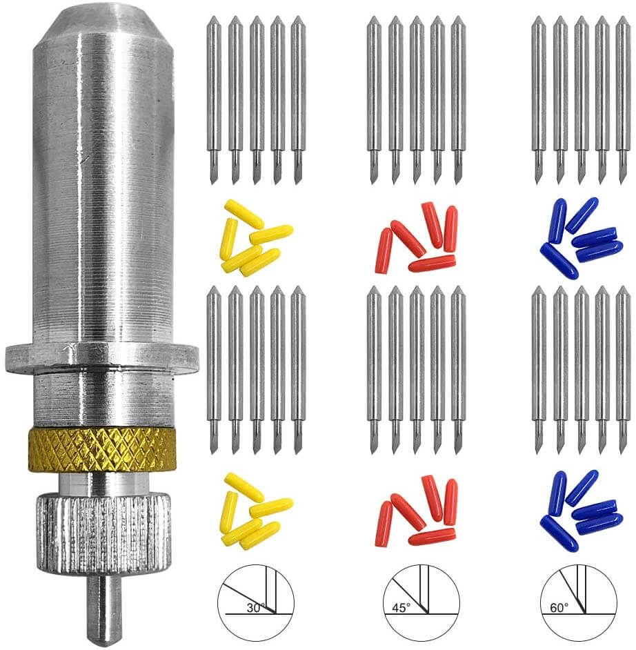
The vinyl cutter in our lab is the Roland CAMM-1 GS-24 model and it came with 3 type of cutting blades, each with differnt angle.
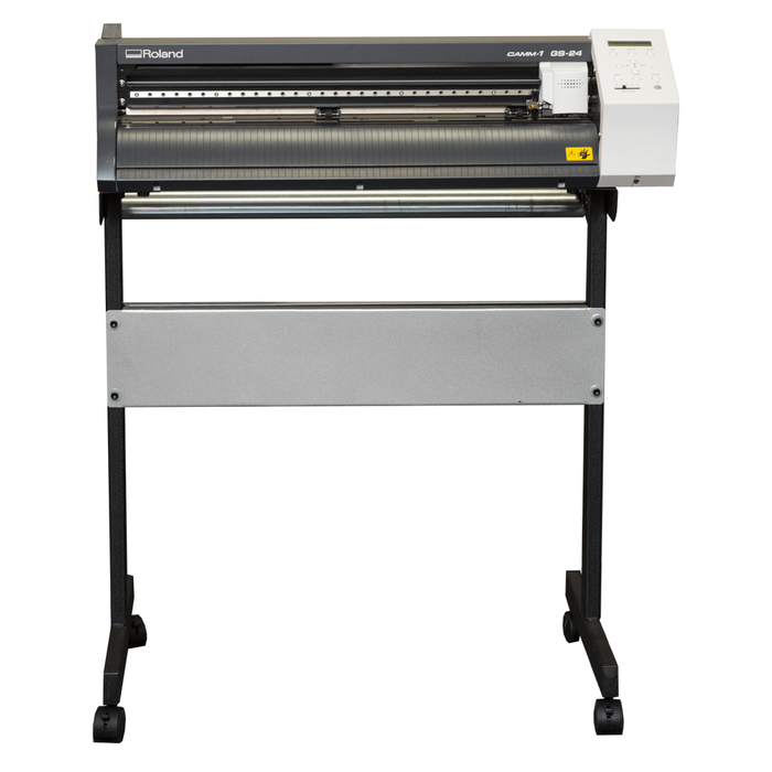
The specification of the machine is shown in the table below;
| Features | Specifications |
| Driving method | Digital control servo motor |
| Cutting method | Media-moving method |
| Max. cutting area | 584*25mm |
| Cutting speed | 10 - 500 mm/sec |
| Interface | USB 2.0 |
| Power supply | Dedicated AC adapter Input: AC 100 to 240 V ±10 % 50/60 Hz 1.7 A Output: DC 24 V, 2.8 A |
| Dimensions (W*D*H) | 860 * 319 * 235 mm |
Source: Global.rolanddg.com
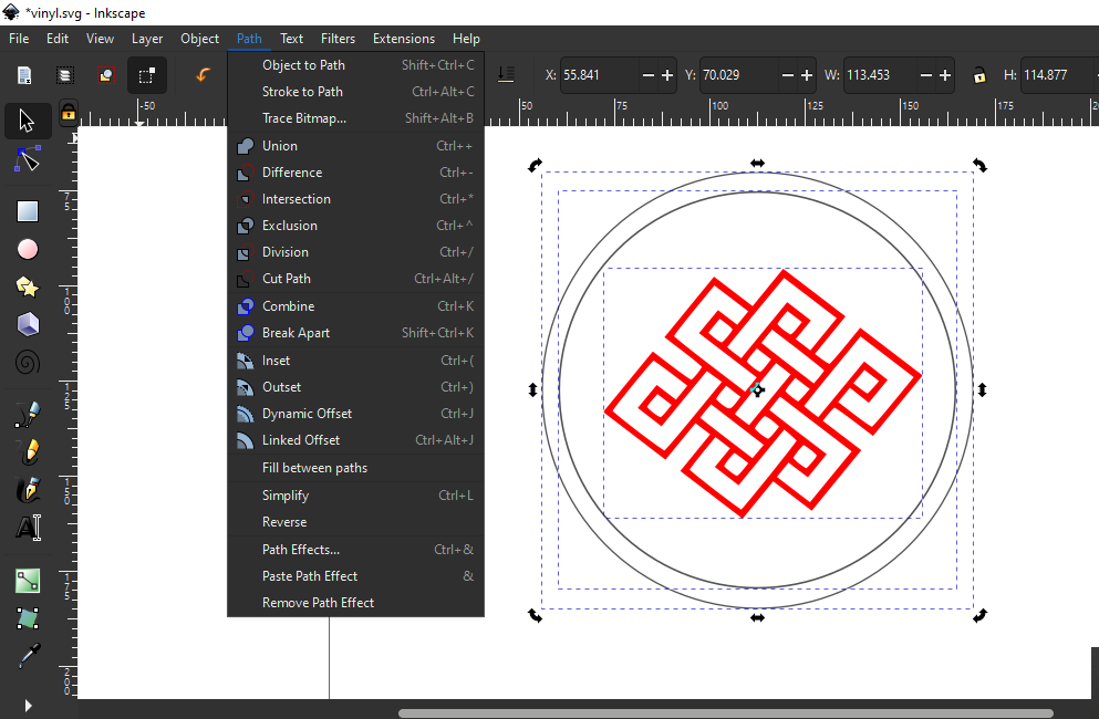
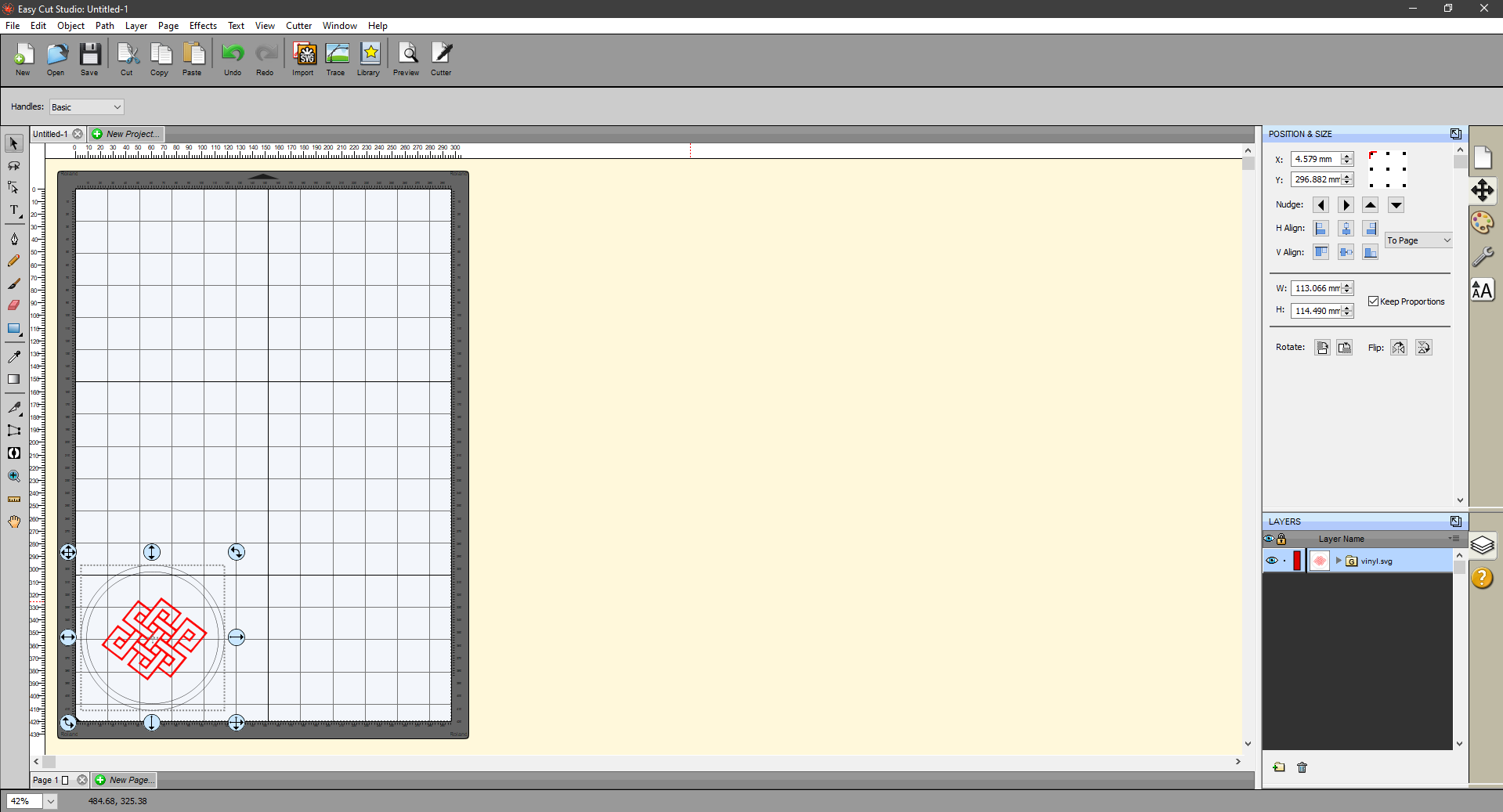
For my individual assignment, I had to learn to use vinly cutter and cut a design I made using the vinly cutter. So, I used inkscape to make a design to be cut using the vinyl cutter available in our lab. I basically imported an image to the inkscape and traced the bitmap.
Then I created some basic schapes for outline.
Once my design was complete, I used the object to path tool to convert my object-design to a path-design. This enabled me to manipulate my design easily.
For this select your design → go to path option on menu bar → click on object to path;.
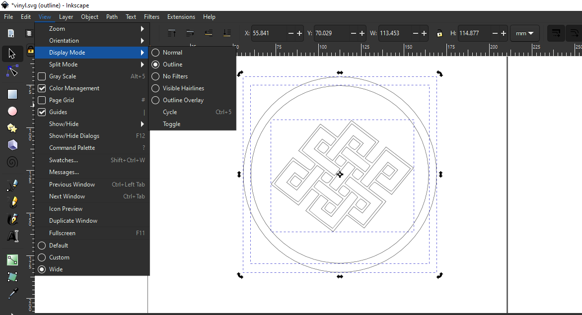
I then used the outline view mode to check how my design would look after being cut using the vinyl cutter.
For this go to view on menu bar → Display mode → click on the outline mode.
The easycut studio software was used to control and feed data to the vinyl cutter. I opened my design on the easycut studio and send the design to the vinyl cutter. When settings kept for cutting are as follows;
Once the design was cut by the vinyl cutter, I had to remove the extra parts using a twiser.
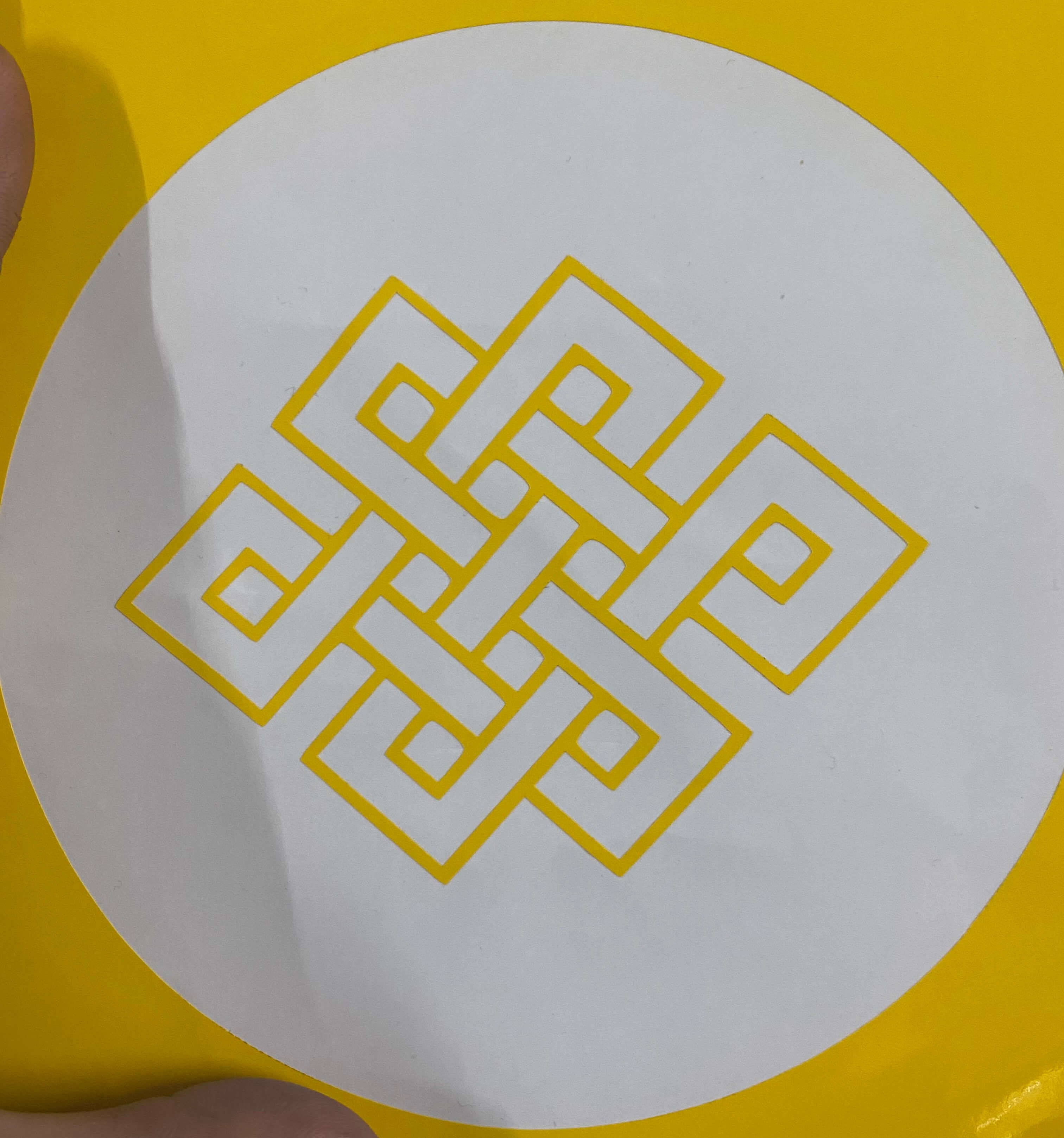
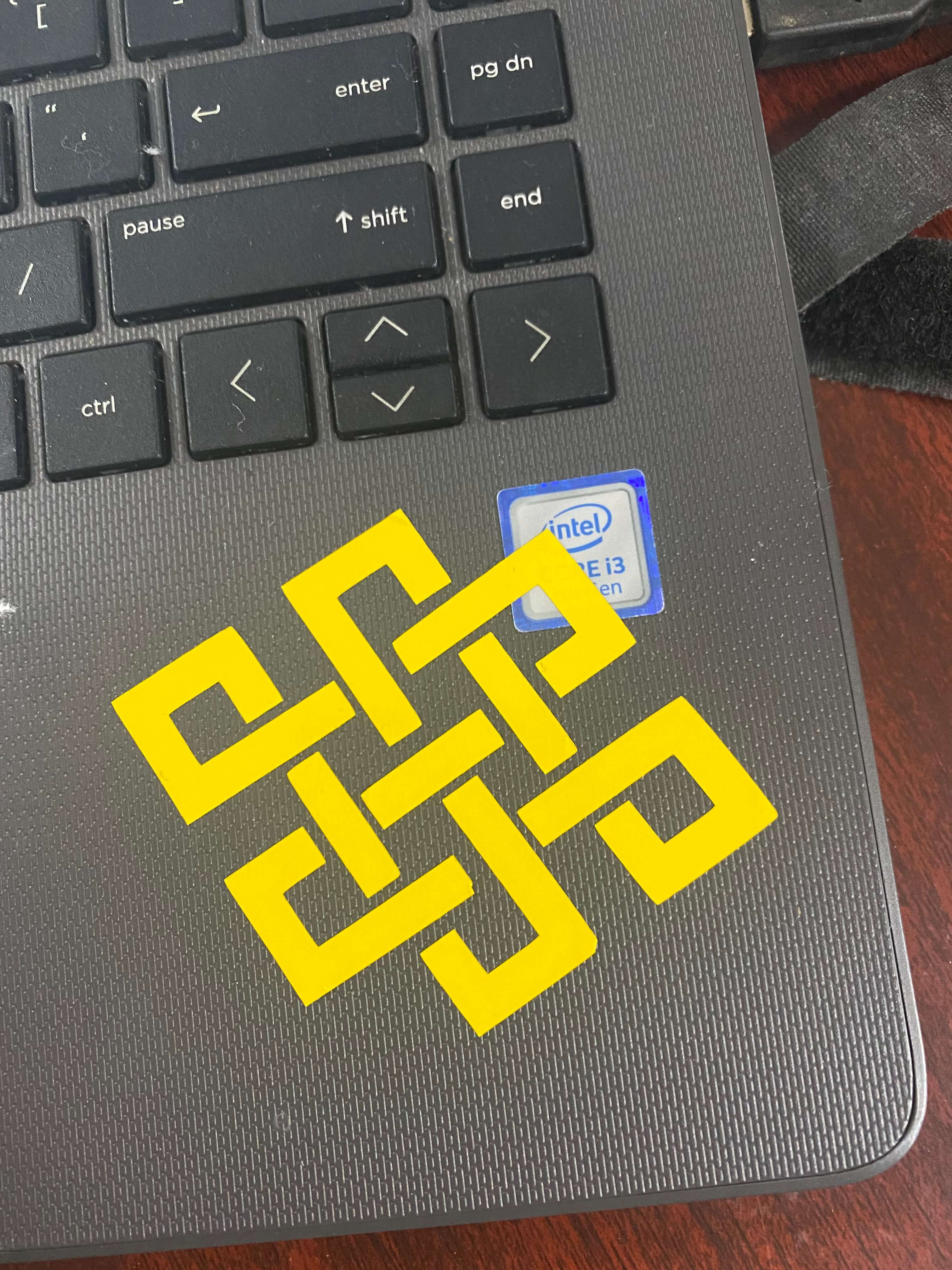
I then used a tape to transfer my cut design from the vinyl sheet to my laptop surface.
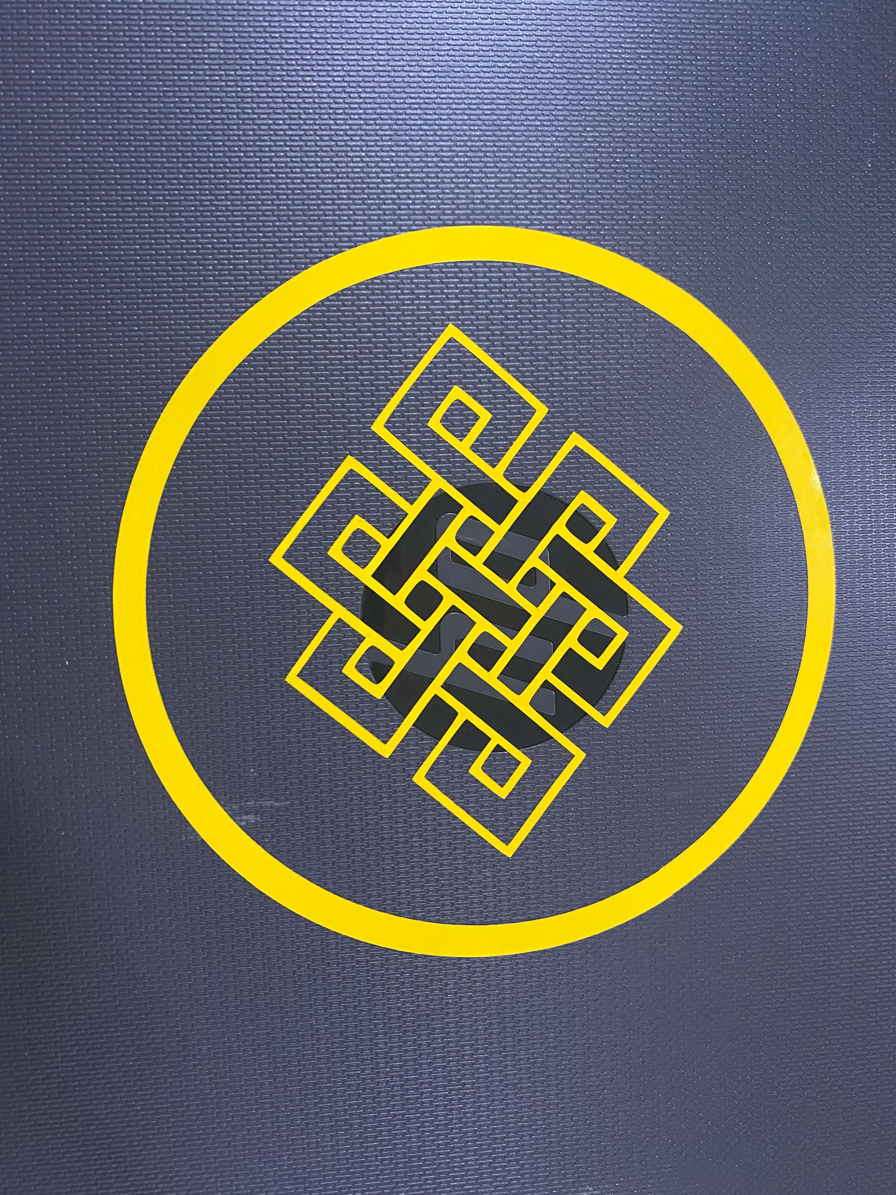
I also used the extra parts I removed from my design to create another sticker for my laptop
Laser Cutter
The next machine that we had to learn about this week was the laser cutter. The laser cutter used in our fablab is of the epilog mini series. The laser cutter has an engraving space of 609mm * 305mm.
The lase uses air to remove heat and combustable gases from the cutting space through an exhaust fan. There is also a red dot pointer to help visualize where the laser will fire.
It also has a high memory space to store multiple tasks and allows files of any size to be engraved. the machine has a movable home position feature that allows us to relocate the home position any any engraving space.
Following table shows the machine specification of the EPILOG MINI laser cutter
| Features | Specifications |
| Machine Size | 876 * 660* 406mm (W*D*H) |
| Power | Auto-switching allows from 110-220 volts, 50-60Hz, single phase, 15amp AC |
| Operating Modes | Rastor, Vector or combined modes |
| Speed and Power Control | Computer or manual control power and speed between 1% to 100% |
| Laser Wattage | 30, 40 50 and 60 watts |
| Maximum material thickness | 140mm |
| Engraving area | 140mm |
| Laser Type | CO2 laser |
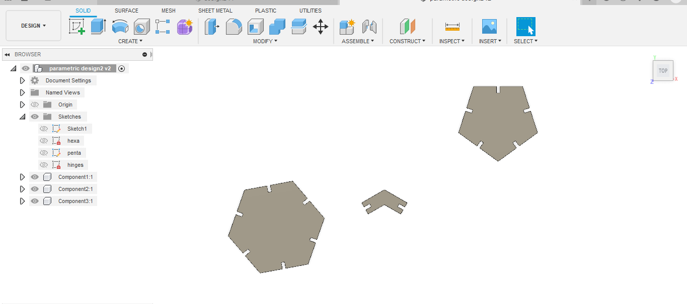
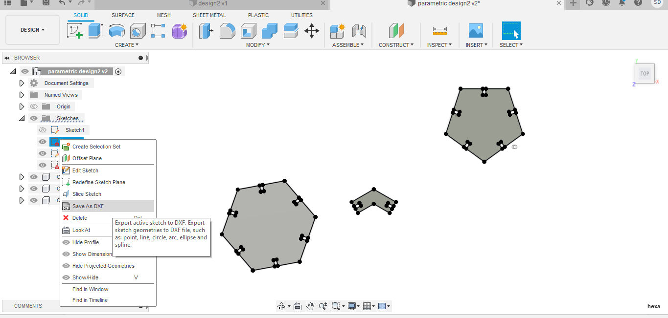
One of the major task of the week was to design a parametric construction kit and cut them using the laser cutter. For my design, I opted for a simple design using basic hexagons and pentagons and joining hinges. I created my design on fusion 360.
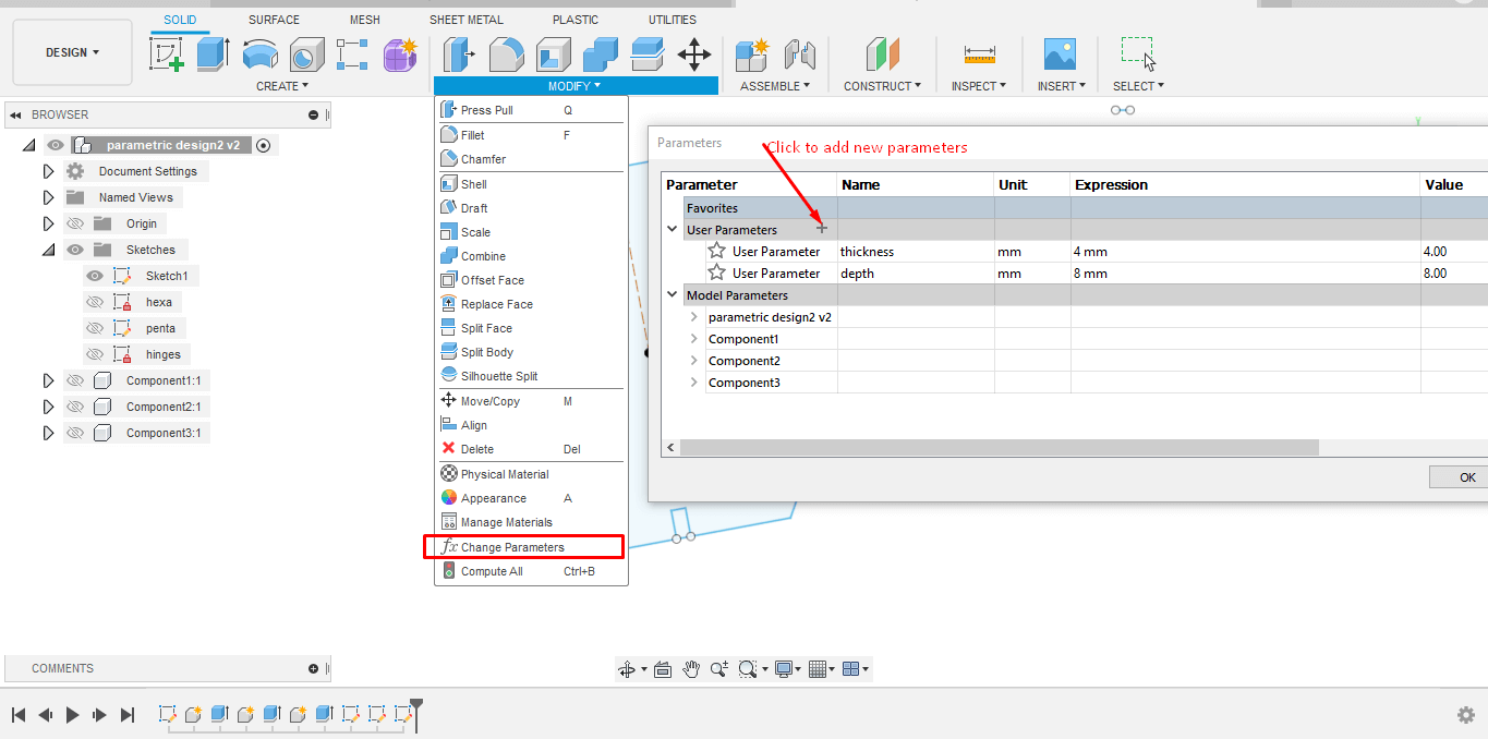
For my design, the first thing i did was set the paramters. For that go to modify → change parameters → click on the plus sign to add new parameters.
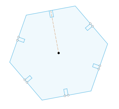
Next created my design. First I created a basic hexagon using the inscribed polygon with a side of size 60mm. Then I created ridges using the line tool on one of the sides.
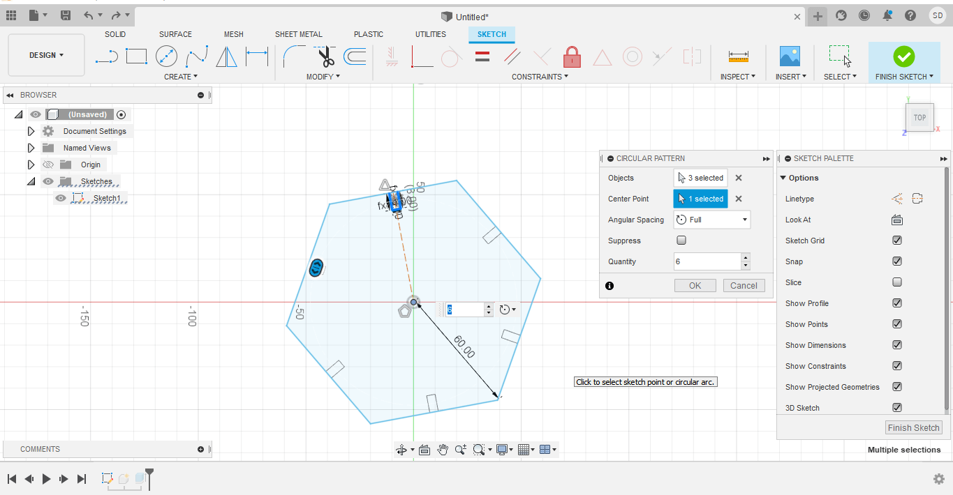
I used the circular pattern tool to create similar ridges on all the remaining sides. For that go to create →circulart pattern → select the 3 sides of the ridges and the center point → on quatity type 6 → hit okay.
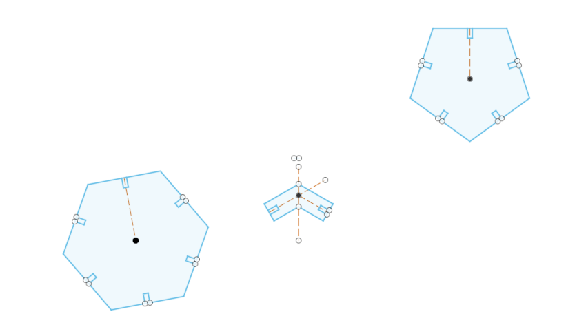
Then I extruded the sketch using the extrude tool. I used the same steps to create a pentagon design and hinges design
After extrusion, this was the final design I got.
For the last step, I had to save the dxf file which could be given as input to the laser cutter machine. For that right click on your sketch → select the save as dxf file.
There were a couple of set backs I had to face when I started cutting my design. First time I cut them, I realized that the size was very big. I kept the length of the polygon sides as 60mm. Thus, I had to redesign with smaller dimensions. The settings used for cutting the design on the laser cutter were as follows;
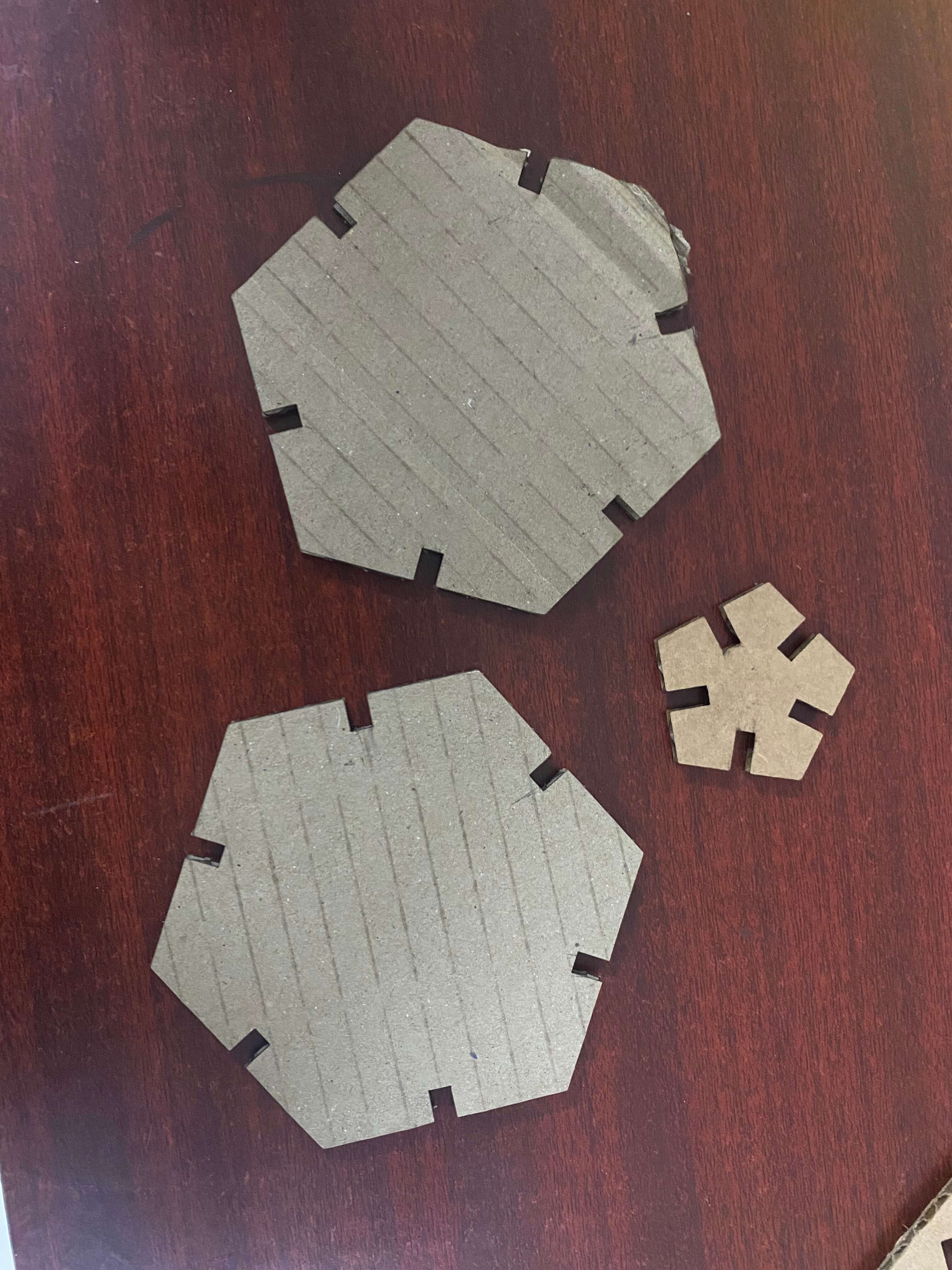
I redesigned with smaller dimension and this was the pieces I cut using the laser cutter machine.
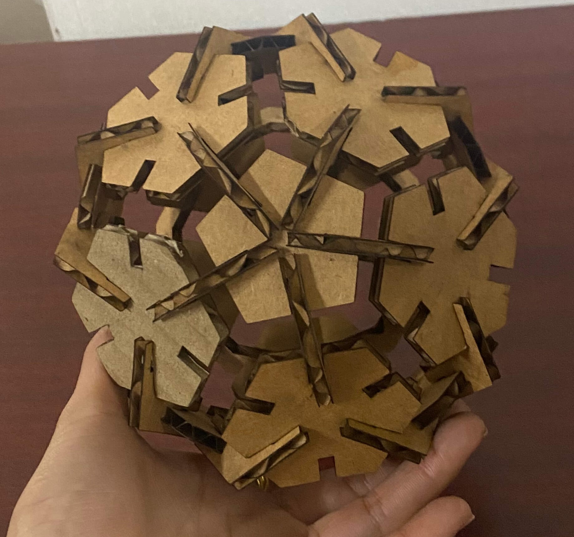
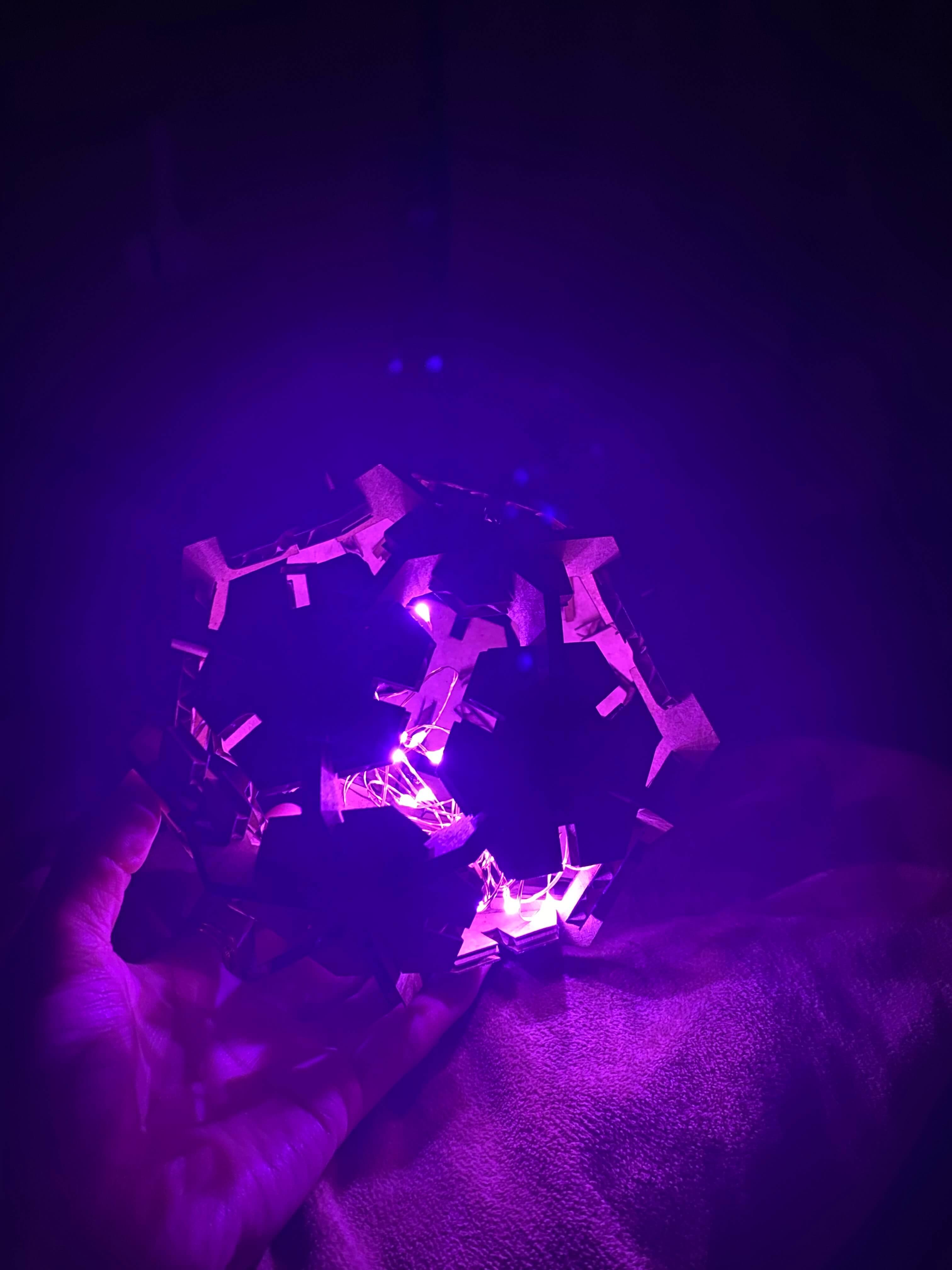
The idea was to create a table lamp in a circular shape. There are still some flaws with the design ( I couldn't make a perfect sphere) but I this it was a good result for the first trial.