Task to be carried out this week
Vinyl Cutting
The vinyl cutter at our lab is the Roland CAMM-1 GS-24 model.
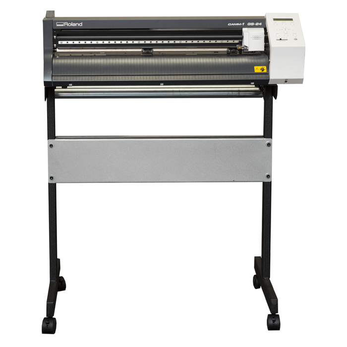
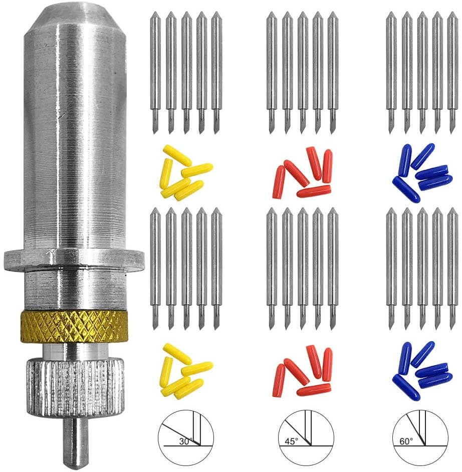
It came with 3 type of cutting blades, each with differnt angle as shown below.
| Features | Specifications |
| Driving method | Digital control servo motor |
| Cutting method | Media-moving method |
| Max. cutting area | 584*25mm |
| Cutting speed | 10 - 500 mm/sec |
| Interface | USB 2.0 |
| Power supply | Dedicated AC adapter Input: AC 100 to 240 V ±10 % 50/60 Hz 1.7 A Output: DC 24 V, 2.8 A |
| Dimensions (W*D*H) | 860 * 319 * 235 mm |
Source: Global.rolanddg.com
Starting and Working with Vinyl Cutter
Laser Cutting
LASER PRINTER - EPILOG MINI
The laser cutter used in our fablab is of the epilog mini series. The laser cutter has an engraving space of 609mm * 305mm.
The lase uses air to remove heat and combustable gases from the cutting space through an exhaust fan. There is also a red dot pointer to help visualize where the laser will fire.
It also has a high memory space to store multiple tasks and allows files of any size to be engraved. the machine has a movable home position feature that allows us to relocate the home position any any engraving space.
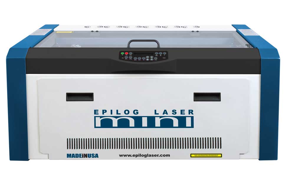
| Features | Specifications |
| Machine Size | 876 * 660* 406mm (W*D*H) |
| Power | Auto-switching allows from 110-220 volts, 50-60Hz, single phase, 15amp AC |
| Operating Modes | Rastor, Vector or combined modes |
| Speed and Power Control | Computer or manual control power and speed between 1% to 100% |
| Laser Wattage | 30, 40 50 and 60 watts |
| Maximum material thickness | 140mm |
| Engraving area | 140mm |
| Laser Type | CO2 laser |
Design Using Coral Draw
We begin with the design of the pieces on the coral draw software. We are working with two designs to test for the power and speed and keef and joint clearance
For the power and speed test, we made an engraving with different power and speeds such that we print them individually to see the difference. Doing so we look at the
level of power used and difference in the engraving. We make necessary settings on the printing software
(Auto Focus, Check Sie of the print and any errors. Then we look at the Laser cutter and set appropriate home point for it to start working
The figure below shows the image we have drawn in CoralDraw to look at the difference in power and speed of the laser cutting machine
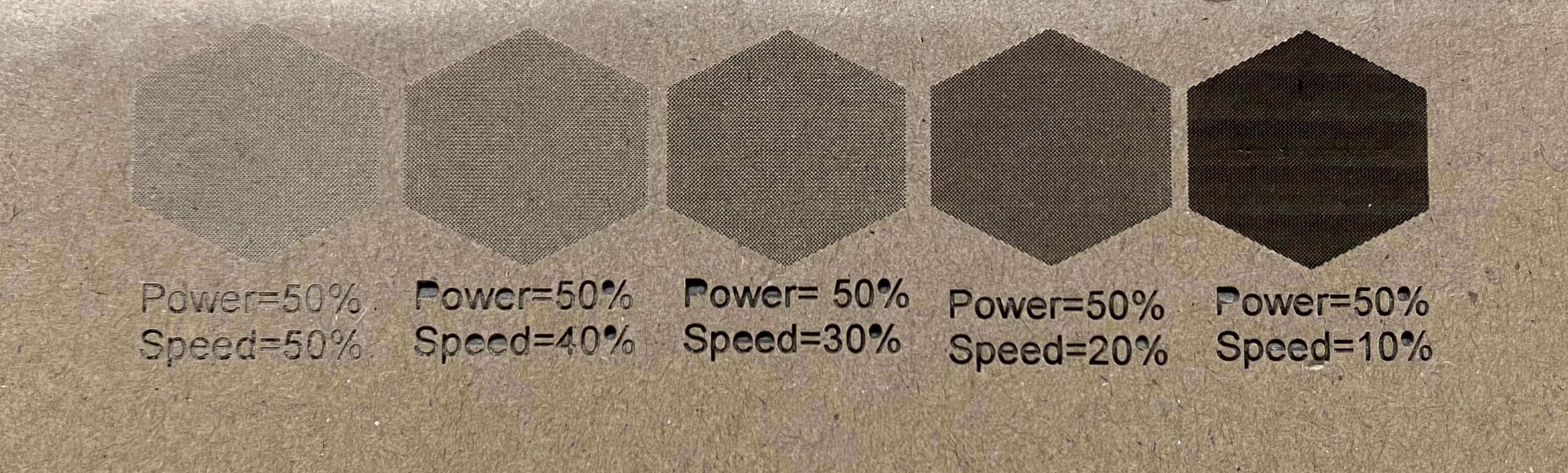
Engraving using same power and different speed
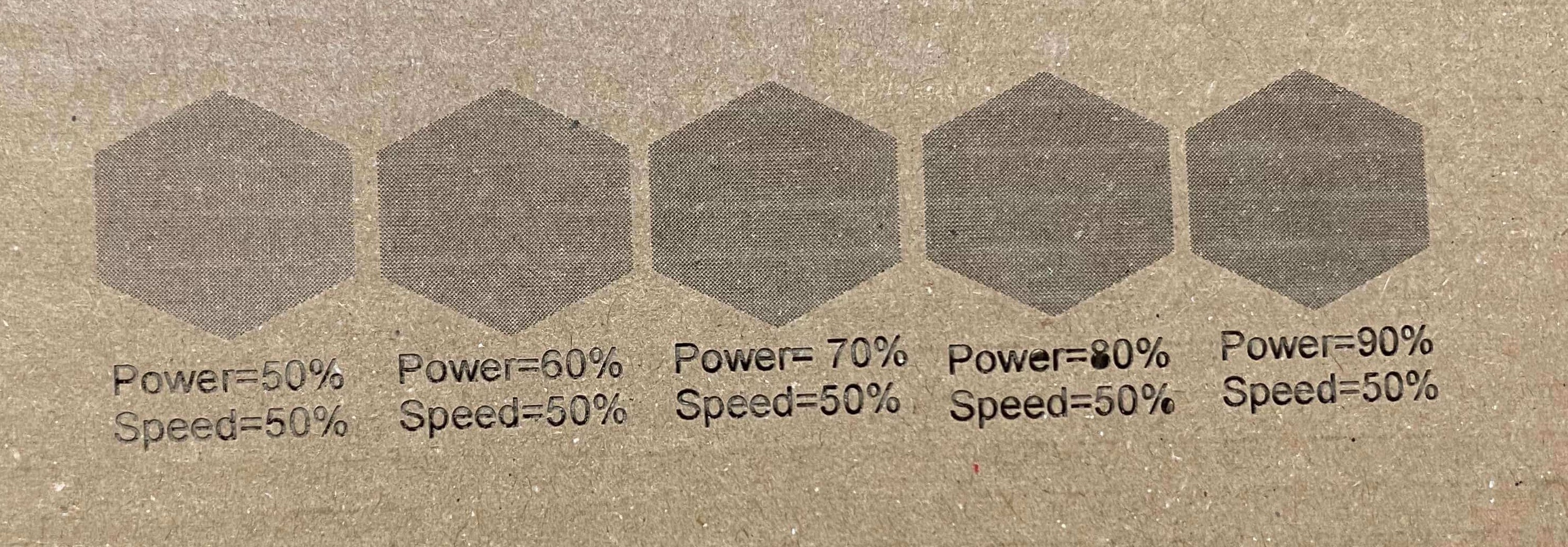
Engraving using same speed and different power
A short Video of the working of the Laser Cutting machine is shown below:
2. Kerf and Joint Clearnace
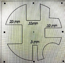
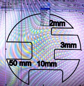
For the Kerf and Joint clearance, we worked on designing a shape with slots and cut it with the laser cutter. Then, using vernier caliper we measured the thickness and width of the slots to look at the errors in cutting. The figure below shows the shape we have made in CoralDraw software and cut is shown below that.
The laser cut piece of the above design is shown below:
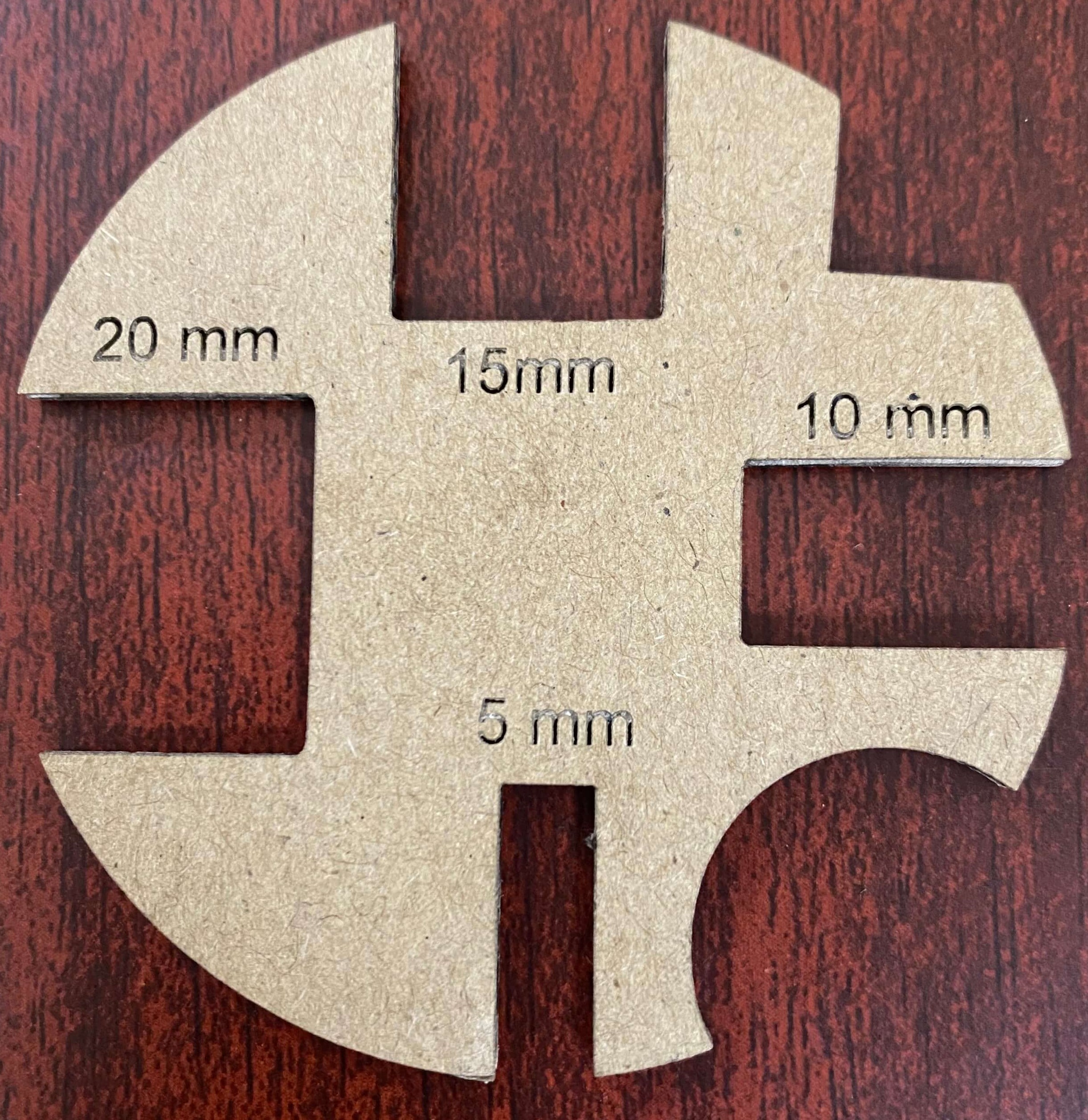
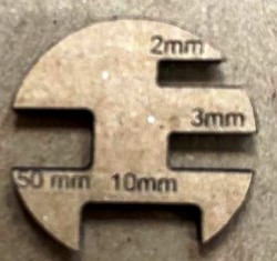
We measured the slot sizes using vernier caliper and compared with the given dimensions. It was observed that there was less than 0.1mm of difference in the slot width and length printed with the laser cutter.
Therefore we considered the laser cutter to be pitched with an error of less than 0.2mm.
Using the data received in the group assignment, we edited the parametric design for individual assignment.