7. Computer Controlled Machining
 This week we are working on Computer controlled machining. The week is also called making something big. The following are the group and individual assignments.
Group Assignment
- Do your lab’s safety training
- Test runout, alignment, fixturing, speeds, feeds, materials, and toolpaths for your machine
The Link to the Safety Training is available HERE while the link to the design and runout test is available HERE
Individual Assignment
- Make (design+mill+assemble) something big (~meter-scale)
- extra credit: don’t use fasteners or glue
- extra credit: include curved surfaces
Individual Assignment
One Sad Story First
So, another fab academy student Anith made an awesome design for the “Make something Big”. I was with him in the CNC room helping because the board i was using was not enough and wanted to add one piece of my design in his board. He had made nice design of YAK head in his object and was cutting with the CNC machine. We didnot think of adding a tab in the toolpath and gave the design to the CNC machine. Since his design had cut pieces of size ranging from five to fifteen millimeters, the cutpiece would come out of the board in the final cut.
Because we were being blunt, we decided to pause the machine and throw the cut pieces as soon as it is done because it would jump up and hit the spindle creating friction and smoke. During the process, we were able to pause the machine and throw the three of the six pieces. On the fourth object, the software did pause but the machine didnot. In doing so, the piece was stuck in the spindle and made a loud noise with smokes coming out and finally breaking the endmill. I was trying hard to pause the machine but by then the damage was already done. It was the last end mill in good condition available in the Lab. https://youtu.be/W1EZQEx6fgM
We had to hard reset the machine and redo the cutting again. But this time, we made sure that we add tabs in the tool path so that the cut pieces would not go flying around. It was a good lesson to learn.
Introduction to CNC
This is the first time i am using a CNC machine and because of its shear size, the time required to accomplish the assignment would also be more. Initially i looked around for links to understand about manufacturing with CNC machine and came on to https://www.youtube.com/watch?v=wsCmJSt-_Bo. This gives us the basic knowledge of why and what is CNC. It also give us a tutorial of how to use CNC to create basic things.
What and why CNC
A CNC (Computer numerical Control) is basically a machine that performs a process based on data from a computer. The CNC is a 3-Dimensional machine that moves based on the coordinated and measurement data provided from a design file. The difference between CNC machine and 3D printer is that, a CNC machine is a substractive manufacturing process while 3D printing is an additive manufacturing process. The CNC manufacturing is also more violent compared to Laser cutting and 3D printing.
CNC Hardware
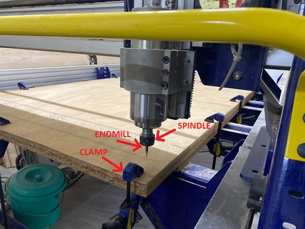
End Mill vs Drill A Drill is used to cut using only it end tip however an endmill sharp edges all along its flute and can survive the lateral loads of being pushed sideways through material.
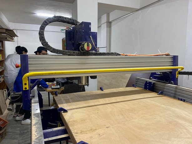
The material is mounted securely on the BED or Table of CNC floor. The table is bolted to the base which supports the rails. The rails allows for smooth linear motion of the router and the spindle. The direction of motions of a CNC machine are X,Y and Z direction.
Because of the way CNC move, the endmill will not be able to reach underneath overhangs and is a inherent limitation of a 3-Axis CNC machine. To move itself along its axis the shopbot uses Motors and pulleys that makes calculated rotations that translates in whatever linear distance is designed. The design commands comes from a mocrocontroller embedded on the shopbot CNC machine which converts machine code to machine parameters including coordinates, speed of rotation and time. The G-code is fed from a computer to the shopbot controller using a USB interface. The PC sends the data to the controller which in turn creates best outcome of the code and triggers the motors to precisely perform any operation.
The operation then translates to the linear motor motion that creates a X,Y and Z direction motion of the spindle and speed of rotation of the endmill to precisely carve out a portion of the desired material.

CAD, CAM and CUT
Design of Parts and Combine in Fusion360
The CAD tool is used to design the idea in 2D or 3D model. For the current case, we can make use of a 2D software such as inkscape and illustrator or we can use a 3D tool such as fusion360. For the current assignment I am designing a laptop table and a center table for my personal use. I have made the design for both using fusion360.
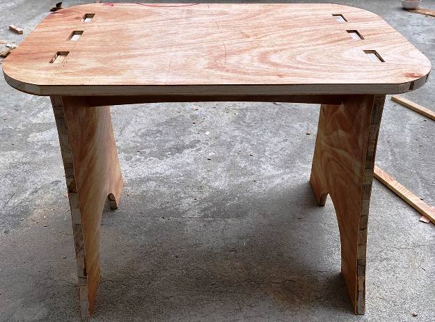
First i design a laptop table the size of 400mm x 600mm in fusion360 with joints such that I donot need to make use of glue or screw. I begin to design all the parts in the same project. I first create sketch of each of the parts. The laptop table has four parts including the top.
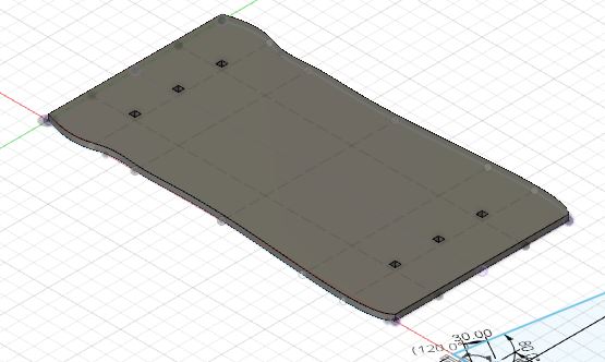
Two legs and a center support that goes below the top and joins between the two legs. It acts as support for both the top and the legs.

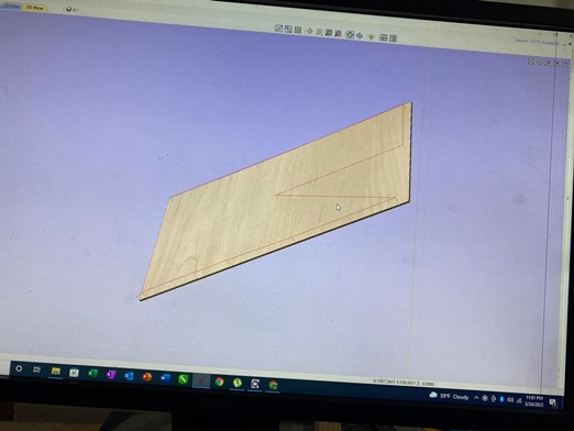
I have made use of spline tool to design the top to have curved shape and also added curved shape to the legs and support.
Further, I make use of assemble to join all parts in Fusion360 and visuallize the combined shaped. The combined shape after construction looks like below:


Design of second Object in Fusion360
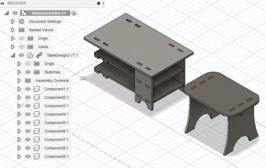
Then i proceeded to design another object that would serve the purpose of a center table. The table has seven parts including four legs, top part and two middle parts. All the parts are designed in fusion360 and uses joints so that i donot require to make use of glue or screw. I first create individual sketches and use extrude command to create 3D version of the parts. Then I proceed with each parts. The board available for us to use has a width of 18mm with other dimensions as 4ftx8ft which is the size of the shopbot table and hence all are design with keeping that value of width. Further, all joints are made uniform at 50mm so as to use parameter in Fusion360 Design and reduce errors in design and cutting.
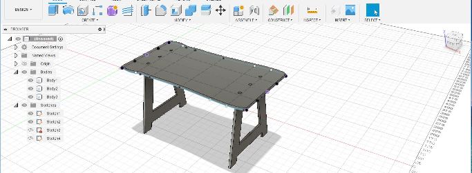
I make assembly and visuallize the components into 3D shape as below:
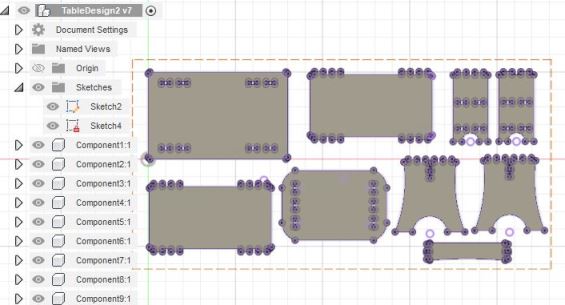
With the design and assembly of the items completed, I move on with the export of each of the parts in a dxf file. Initially, all bodies are created into project using project command in fusion360. with the project created, the files can be downloaded as individual dxf file or combined. I created a sketch of the size of the board and arrange all parts into that size to look at the final cut on board in shopbot. This also helped me see if all parts will fit into the board. After completing that i realized that all parts will not fit into the board and will be left with two legs of the second design that needs to be cut in another board.
The dxf file for the above is found in the files at the end of the page.
3D Models
Design file DXF
Design file Assembly
Export DXF to Shopbot
With the 3D design completed and exported in DXF file format, I move on to shopbot machine and its connected computer. The files are first downloaded to the local drive and then imported in Aspire software to create tool path. If the file design are arranged and sized together on Fusion360, the file can be directle imported as a single file without need to arrange on aspire software. We go to file > newproject. Keep the settings at single sided with size as the size of the shopbot table or size of the board in use.
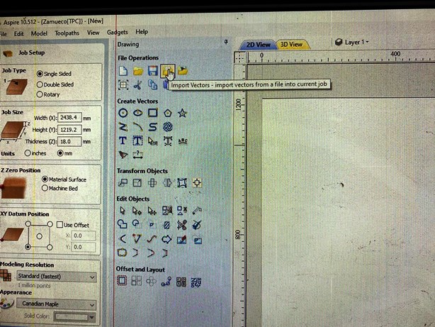
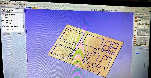
With all other settings as default. We move to Import Vector, and open the DXF file from the drive. The tool available in Aspire is Transform tool to move the parts into the frame of the aspire.
Create Drill toolpath in Aspire
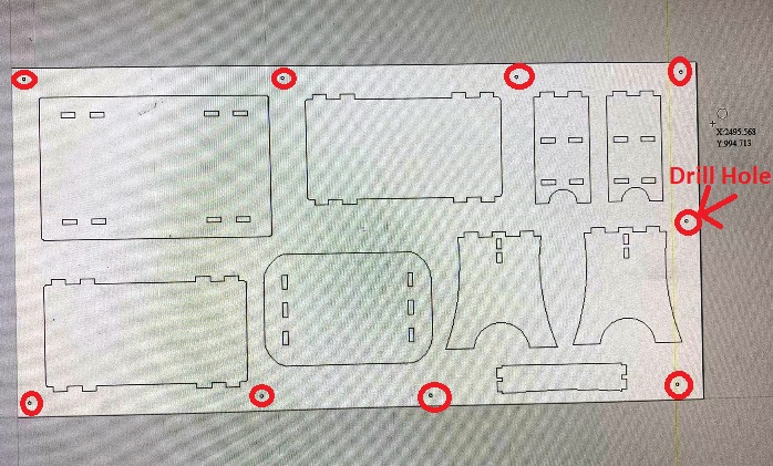
Once the objects are properly arranges in the Aspire window, we make use of Circles to create drill hole. The size of the drill hole is kept same as the size of endmill and proper care is taken so that the drill hole are further from the tool path of the objects to be cut. The number of drill hole are chosen in arbitrary way so that all part of the board would be properly fixed and aligned to the bed of the the shopbot.
Then we select only the drill hole and create the tool path for the drill hole.
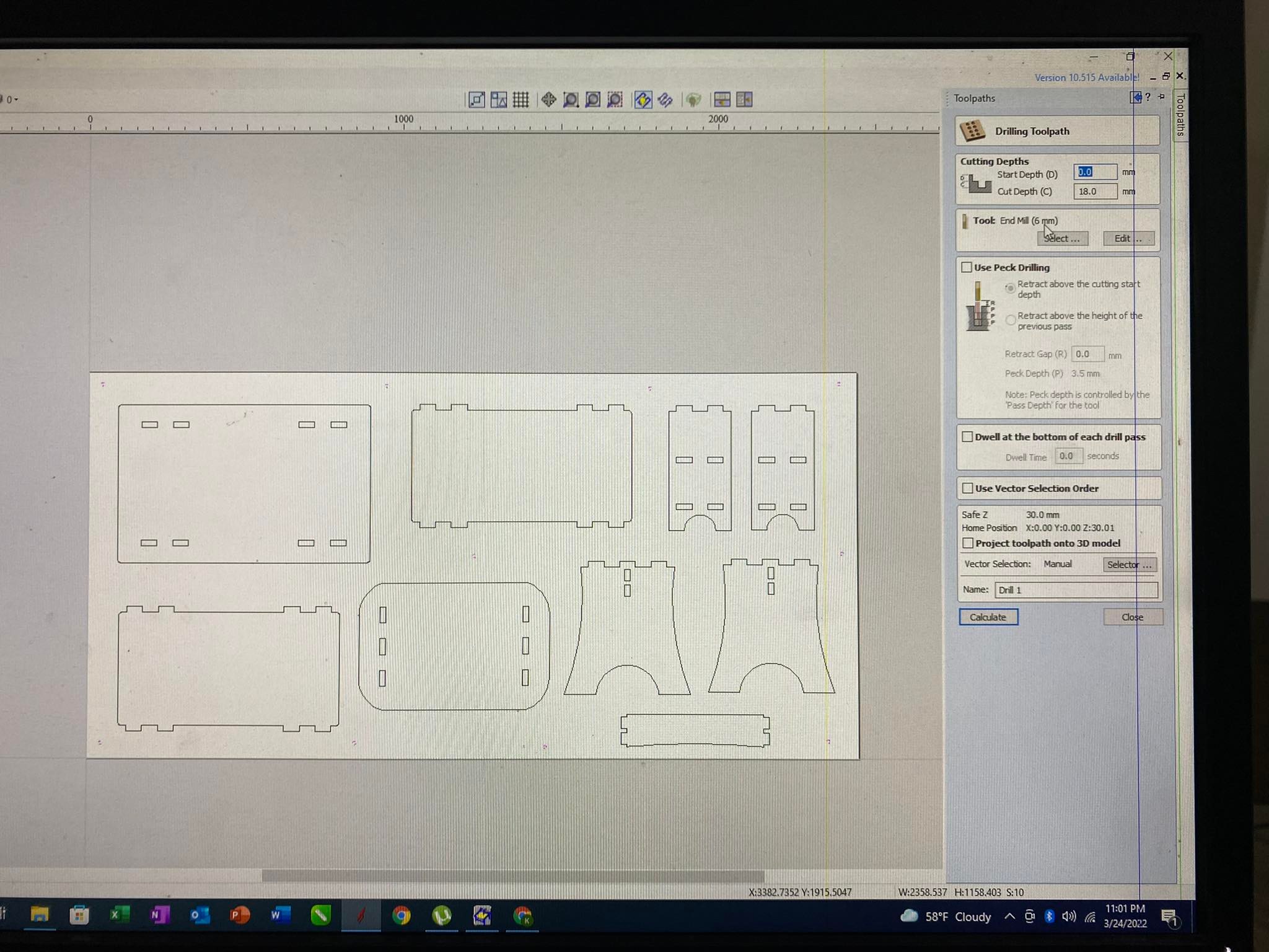
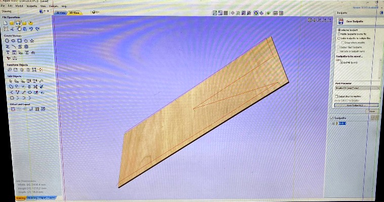
 To create the tool path, we go to toolpath > Drill Tootlpath. Under the toolpath we change the starting point to 00, and end point to the thickness of our material i.e 18mm.
Cutdepth setting
Depending on the driver for the shopbot and the setting of the Z-axis, sometimes it leaves a thin surface that is not cut when setting the cut depth to the material thickness. With trial in the group work we had the material cut properly in the first phase but when the shopbot got reset the cut depth had to be increased to 18.5mm for the shopbot to cut the material completely.
With the cutdepth settings, we can also make change to the tools by editing the tools setting.
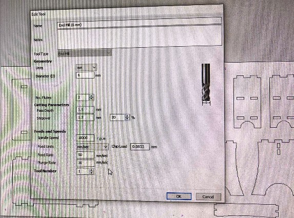
Changing the tools Settings
The global tool settings should not be changed else it will change for all jobs. We can edit the tools for the current job only if required. The following is changed based on our requirement for the tools settings:
- Number of Flutes: 2
- Pass Depth: 3.5mm
- Step Over: 1.2mm
- Feed Rate: 50mm/sec
- Plunge Rate: 30mm/sec
- Spindle Speed: 1800RPM
With the tools settings changed, we press calculate to calculate the toolpath. Then we close and then save the toolpath in the desired location. We can also visuallize the tool path in 3D to look at where the drill holes are going to be.
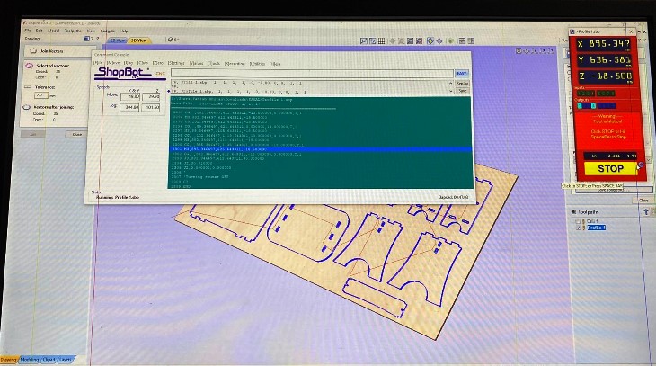
Create Profile toolpath in Aspire
Similarly we can create the toolpath for the objects to be cut in aspire software. The tool path is created using the profile tool in aspire with the cut depth setting same as the the drilling toolpath.
Then we can save the tool path after changing the tools settings if required.
Use Tabs to hold parts in Final Cut
We have to make sure to add tabs when creating the tool path in Aspire. Tabs leave small places in the cut that can be removed easily but hold the parts in place during cutting process. The software automatically calculates the places to add tabs when we make the add tabs selection. We learnt the lesson the hard way in the story at the begining of this page.
Cutting in Shopbot
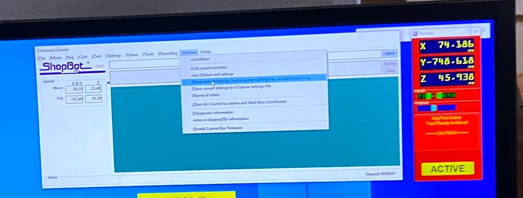
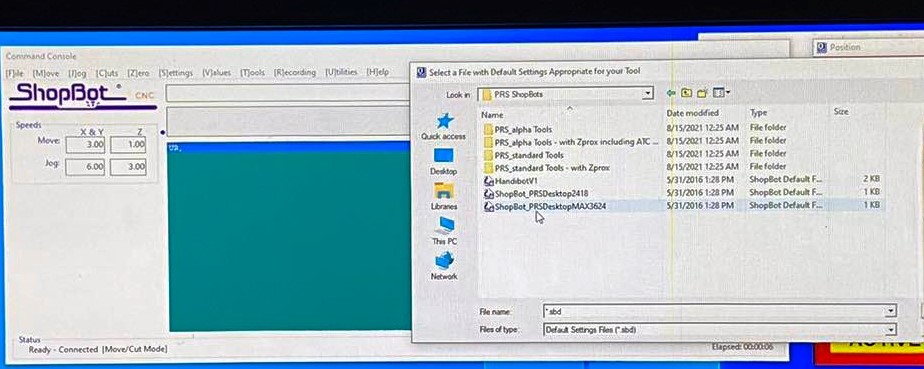
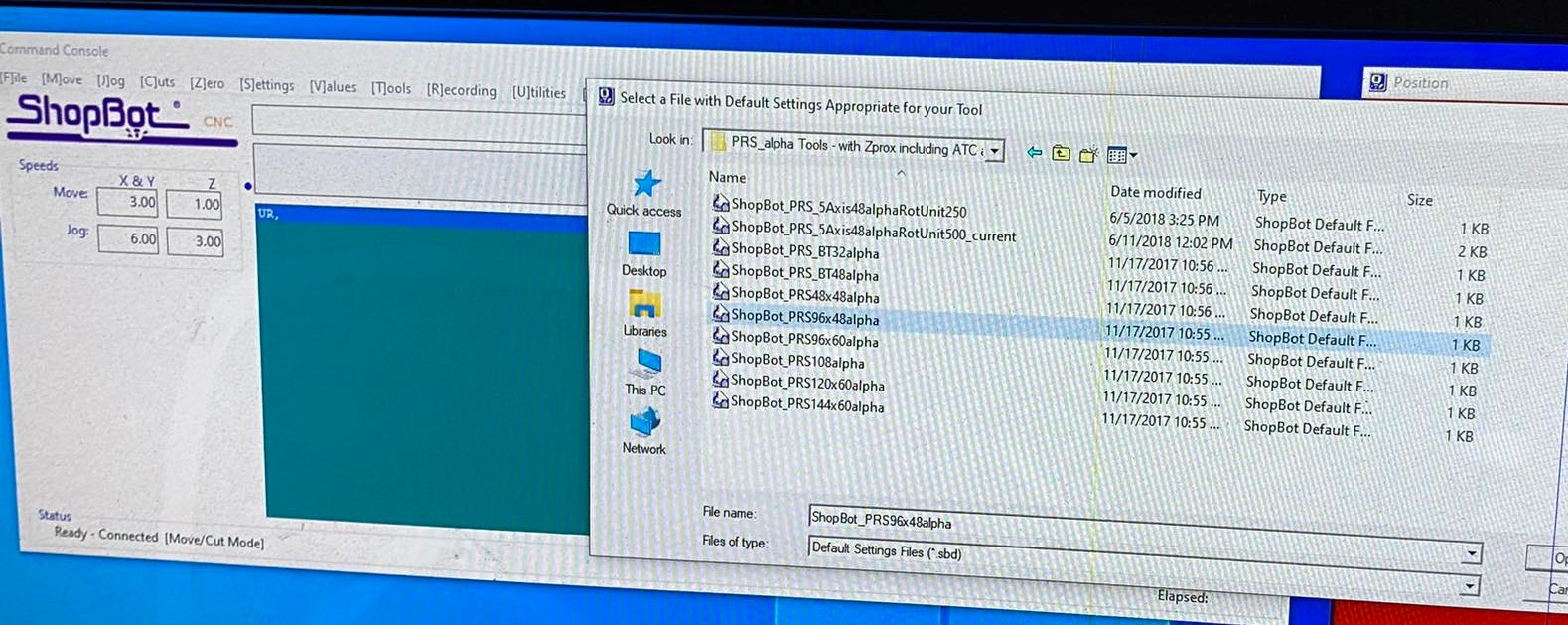
With the toolpaths saved, we proceed to importing the toolpath file to the machine software. The shopbot software has two interface. One is the direction control and the other is the command console. The direction control interface can be used to control the shopbot and import the toolpath. First we have to place the board on the bed of the shopbot and align it for drilling. Then we change the desired endmill.
Changing the Shopbot Endmill
For the shopbot, we have a number of different endmills we can use for different purpose. CNC machines use end mills that cut laterally (side to side). End mills have cutting surfaces called flutes. The most common end mills have two to four flutes. Generally, fewer flutes evacuate more chips from your material, keeping the bit cool. However, more flutes produce a finer edge finish (Source: Google Search).
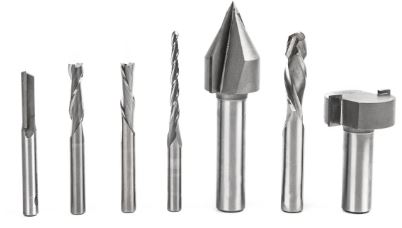
For the current work, we make use of the following endmill given the thickness of board at 18mm:
- 2-Flute Endmill
- Diameter: 8mm
- Total Length: 40mm
- Cut Part Length: 25mm
- Material: High speed steel (HSS)
In order to change the endmill, we make use of wrenchs to remove the spindle-end and remove the collate.
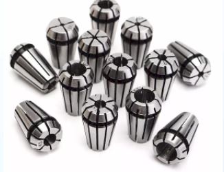
The collate is designed to hold the endmill properly. Each collate is designed for a size of endmill. With the endmill fixed to the collate, we fix that to the end of spindle and tighten it with wrench. Care should be taken so that the endmill is properly fixed so that it donot move around in cutting process.
Then we set the XYZ axis for the shopbot. We use the direction control to move the shopbot in XYZ direction and bring it to the desired location to set the XYZ zeros.

With the zeroing done, we load the drill toolpath on the shopbot software and cut.
Starting the Shopbot Spindle
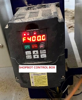
For the shopbot in lab, the spindle donot start automatically from the shopbot software. When we start the cut from the software, the program pauses for the spindle to be started. We have to manually start spindle from the control box on the side of the shopbot. We can also change the speed of the spindle using the potentiometer on the control box. We START with the green button and STOP with the red button manually.
Spindle Speed: 4000RPM is needed to be set for the shopbot manually from the control box. If the speed decreases, the cut will not be even and as desired.
Once the spindle has started, we resume the cut on the shopbot software. Then the shopbot will begin the cut process.
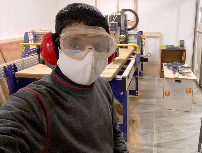
Proper Gear and Emergency Stop
- From the safety training, We should make use of PPE for dust
- Safety goggles are important to protect the eyes and
- Noise reducing head sets should be used to protect our ears from the loud sound in cutting process.
- Finally, we keep our hand on the emergency stop button should any mishaps happen.
Once the drilling process is completed, we have to put the screw in place. We make use of hand drill to screw and fix the board in place.
With the board fixed properly we proceed to importing the toolpath for the profile in shopbot and send it to cut.
Stuck with Error
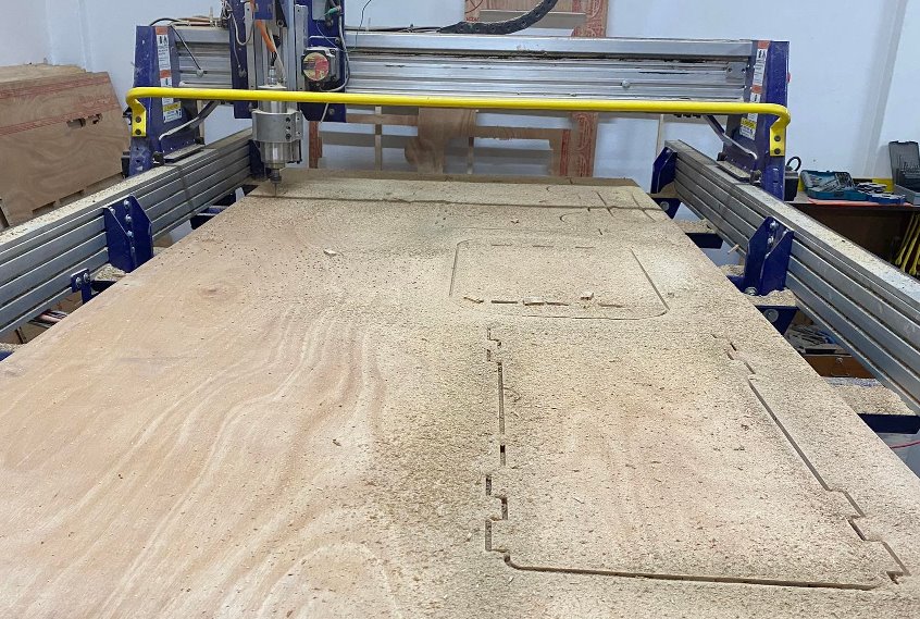
During the process of cutting the first part, it went smoothly and I was able to cut the parts properly. Then the remaining two parts, I proceeded with the cutting process but was stuck with some unforseen error. The error was as shown below:

The error would popup everytime we tried to open the shopbot software and would not come up. We tried an couple of fix by restarting all the devices without success. Then we called on an expert in the lab to resolve the error. The error was only solved by rolling back the driver and reinstalling it.

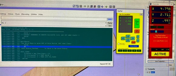
With the drivers reinstalled, we have to test the z-axis zeroing and test whether the driver is properly installed. We use to zeroing touch plate to zero the z-axis. In the shopbot in lab the auto z-axis zeroing was also non-functional. The z-axis zeroing has to be done manually by using the keypad on the shopbot software and using a paper to check for z-axis zero positioning.
Final Cut Parts and Assembly
The followings are the steps we use after the cutting process is completed:
- Stop the spindle of the CNC using the red button on the manual control box.
- Remove the individual parts and dust off or vacuum the dusts.
- Remove all the screws previously installed using hand drill
- Remove the remaining board and keep aside.
- Move on to assemble the parts and make sure all joints are proper.
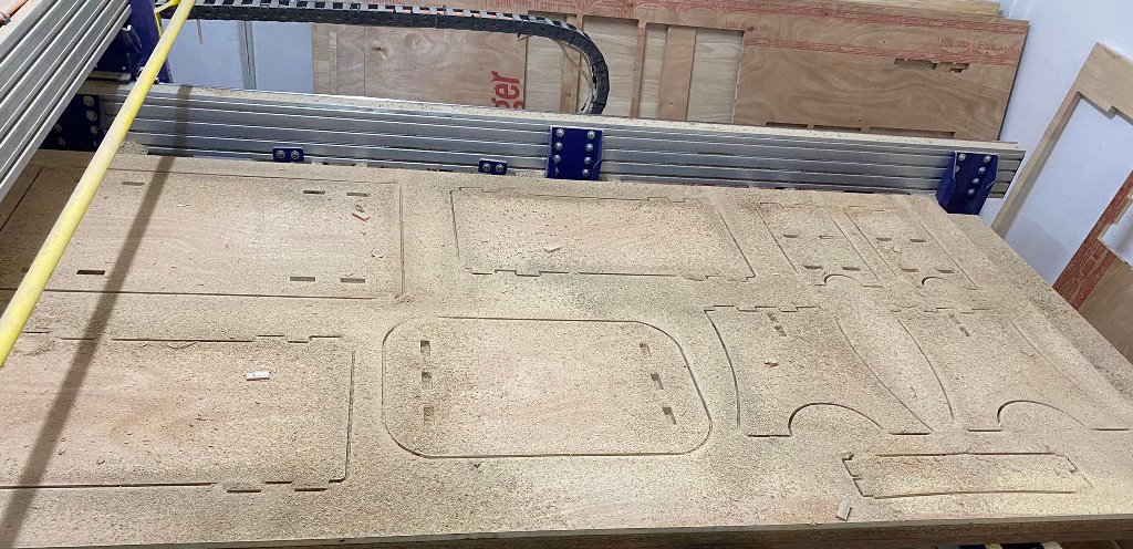
The material available to us for the shopbot assignment was 18mm plyboard with wooden fillings between two plyboards. Therefore we could see places in the cut parts that had open fillings. We had to first use sandpaper to sand off the coarse materials around the cut pieces, the made use of saw dust and fevicol glue to close the holes due to missing filling materials in the board.
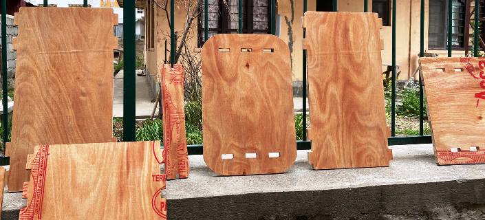
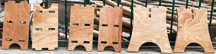
Then I assembled all the pieces together and checked for errors if any. The final assembled parts are shown below: