8. Computer controlled machining
This week on computer controlled machining, I planned to design a shelf on fusion 360 and it would take a while for me to complete the work on using the machine to fabricate it. Because of the Fabzero program we are working on the installation of the machine in our schools fablab.
Group Assignment.
My group assignment can be found here.
Task: Computer-Controlled Machining
- Group assignment:
Complete your lab’s safety training Test runout, alignment, speeds, feeds, and toolpaths for your machine Document your work to the group work page and reflect on your individual page what you learned
- Individual project
Make (design+mill+assemble) something big
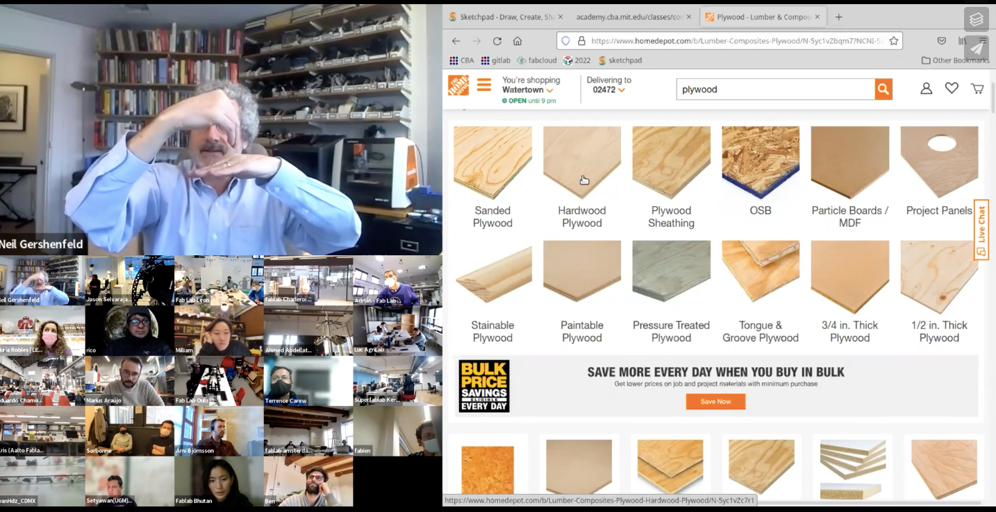
Shopbot
Short for “shopping robot”, an intelligent software agent that can automatically search a large number of online stores for a specific product. Shopbots enable consumers to make a comparison shopping by displaying on a single page the prices and features of a product offered by different vendors. igi-blobal
Also while documenting this work we are working with Fran and Sibu for installing the Shopbot and other Fablab Machine.
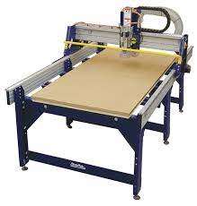
Shopbot is a 3 dimensional milling machine whcih follows the tootpath and measurement based on the design files arranged on thw machine software.
SOFTWARE
The software used to computer controll the shopbot are:
- Controllor software:
- SHOPBOT 3,
- COMMAND CONSLOE,
- V-CARVE FOR GCODE GENERATING.
3D Design
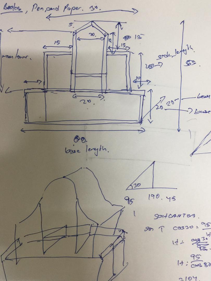
Before designing the shelf I started with a sketch on a piece of paper. The image below shows the concept design of my shelf.
I used Fusion360 to 3D design my work. The file below is my fusion model the shelf.
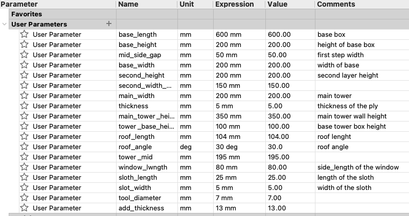
First before designing the model I defined the parameter based on the concept design as shown above. The image shown below is parameter defined for the design.
To use this model in the cnc machine we have to export all the components as DFT file. To do that the process involve are:
- Click on create sketch.
- Select one of the plane of the components.
- Then click create, project / include and the select sketch.
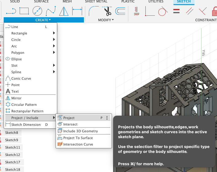
- And then select the plane you want to export.
- Finally finish the sketch and right click the sketch generate and click save dxf.
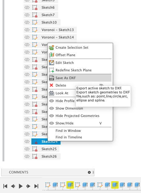
After doing this step for all the components of the model. Take this files to generate the g-code for the CNC machine.
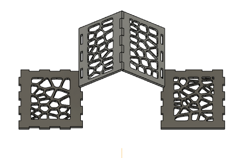
To design the roof of my shelf I used the Voronoi generater to create pattern.
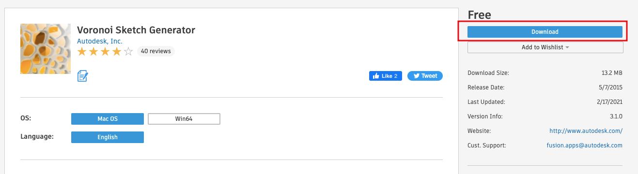
Then Installed it:
Then I used the plug-in to gernerate patterns in my design.
Since we wont be able cut a rectangular slot. Therefore we will be using the fusion360 Dogbone add-in. I refered the given youtube tutorial.
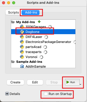
To add the dog bone Add-in to fusion, we used this Link to download and install the Add-in.
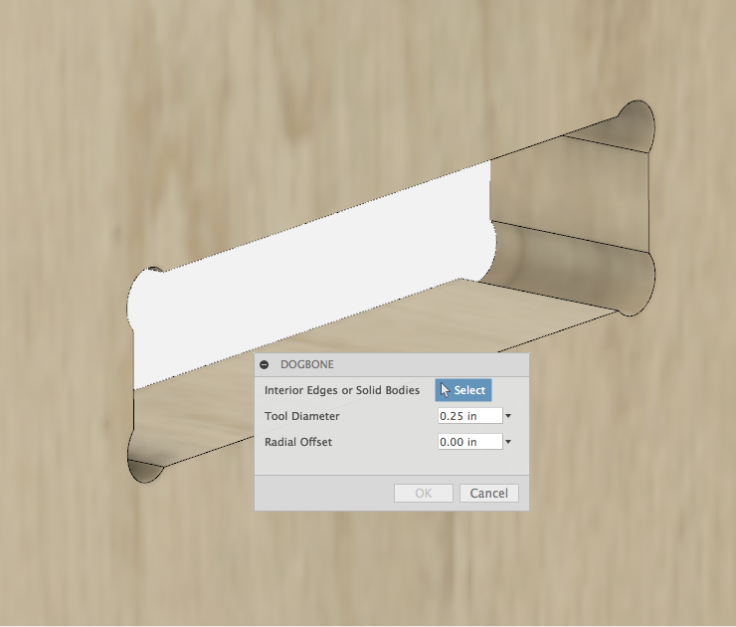
Dogbones in the joint helps us create space at the corner of the joints
And the next step was to add the add-in to the software, so that we will be able to use it make changes in our design.
All the dimension in my design are in the parameter, so that it would be easier for me to update the design later.

Working with the shopbot.
And Finally almost after a month, I was able to come back to the lab. The lab provides a very good working enviroment and its always great to work with the other participants.
Setting up the material.
The material is mounted on the CNC bed
And holes are made on the board by following the process.
- First click the drill toolpath
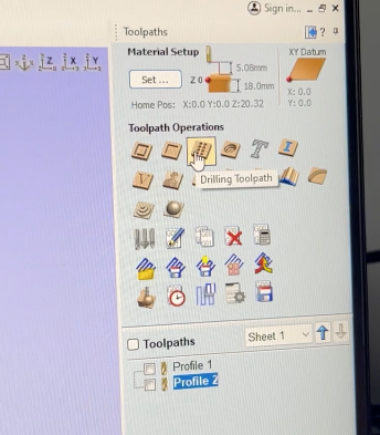
- Then set the cut depth, start depth based on the thickness of the board and size of drill bit.
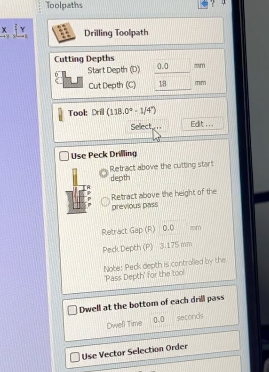
- Then locate the drilling place and then drill it.
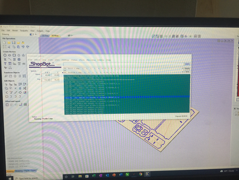
The machine software used to controll the shopbot is called Vcarve. The process to process the file for shopbot is
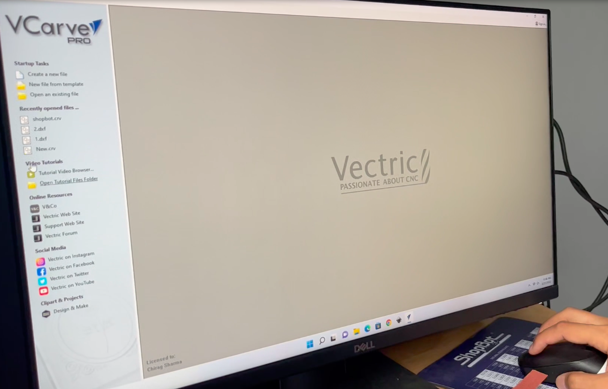
- First create new file and on your left hand side and add the basic job setup.
-
Next step is to import the DXT file to create a layout for the boad cutting.
-
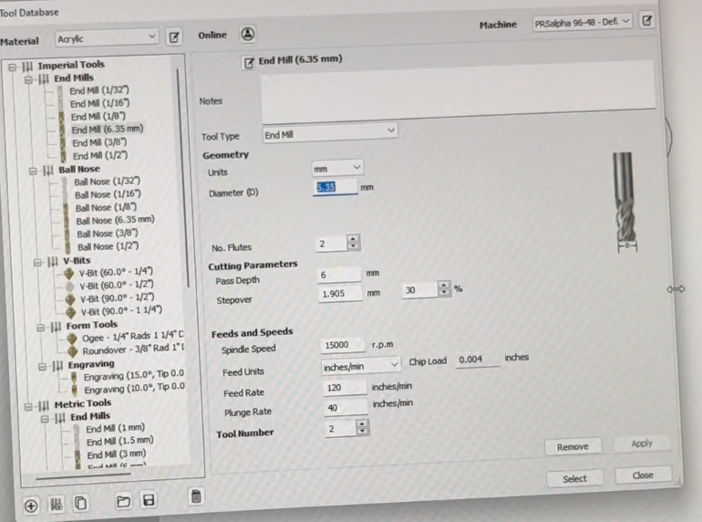
Then creat a toolpath. Set the cut depth, start depth, tool and create profile. And other option like speed and stepovers can be set here to.
- Remember to add tap to avoid flying wood block.
Finally press calculate. Save the toolpath.open the shopbot software.
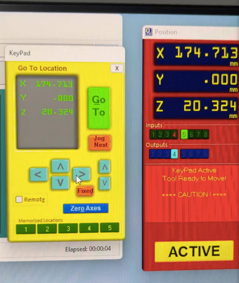
From here we can set the origin and maintain the coordinate.
Next after setting up the origin. Add the saved tool path file and start the shopbot.
The video embedded below provides a very good brief introduction on using Vcrave.
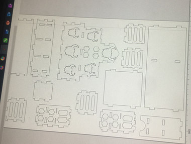
The image below is the clicked image to show the arrangement of the DXT file on the board. Since I was having some space in my board, so other participants also added their DXT sketch to be cut.
After this the machine started to cut the outline for my shelf.
It was a good start.
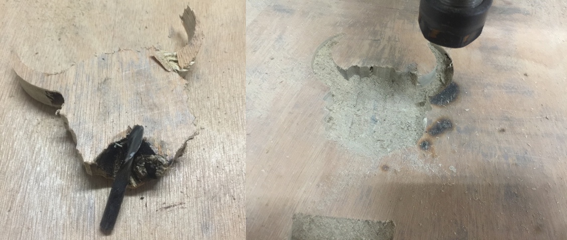
The video below is a short vlog on shopbot. During the process, I broke the only good drill bit left.
- Moral : I should have used Taps on my designs so that this incident won’t had happended. Heres a clip of it.
The incident happened because it was supposed to cut out a yak head outline from the board. If taps were used then this wont had happened.
And then to complete the job for the machine. we kept the origin same like previous one and deleted out the completed 2D sketch from the toolpath.
But due to the incident, the coordinate of the machine had seemed to be displace by few mm. I tried to capture the affect of it but the vide is not so clear.
Basically the problem was that the drill bit had shifted few mm towards left side hence affecting the dimension of the my main back cover.
Since the other drill bit was little blunt which also affected my design since the cut-out were not having smooth edges.
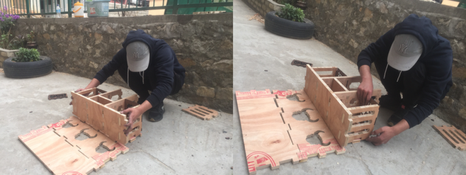
Finally all the blocks were cut but joints were not good enough to fit in well. Lesson Learned. - It would be always best to keep the female joint atleast 1 to 2 mm wider than the male joints. - But the other reason was due to the displacing of the coordinates of the machines. Therefore I used sand paper and metal file to adjust and assemble the parts.
But there came another weird in my cutouts. The slot below has a width of 6mm compared to other slots.
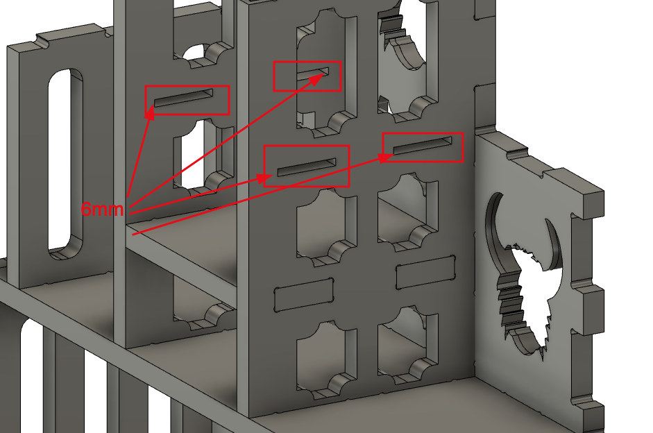
But in the cutout parts, these slots were missing. Instead of the slots, holes were made on the cutout.
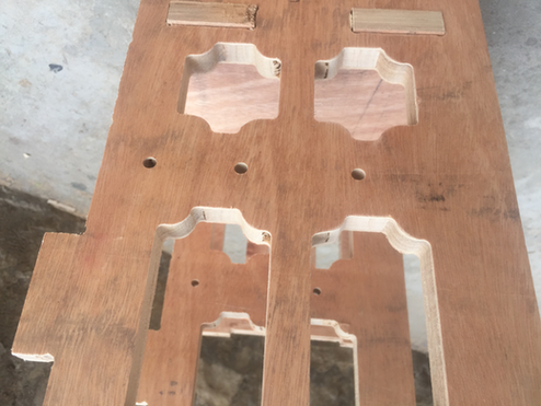
The reason is most probably because the diameter of the tool it self was 6 mm and hence the slots were not made.
Since the roof of my shelf had the voronoi pattern, hence I decided to laser print the the roofs on a 5mm wood.
Laser cut of the roof.
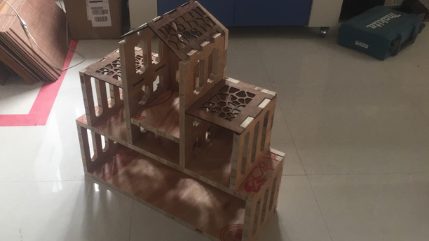
Finally after filing the joints for some times, we were able to assemble all the components of the book shelfs.
Except for the roof of the shelfs. The files were exported as DXF files and imported to coral draw to cut out the pattern on a plywood of 4 mm size.
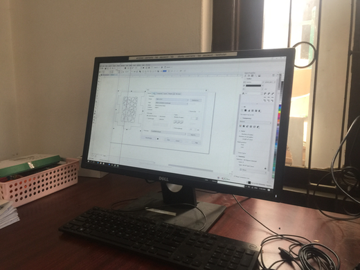
The settings kept to perform the operation are: 1. Power : 90 %. 2. Speed : 20 % 3. Frequency : 2500 Hz. 4. Auto Focus turned on.
But the laser was not able to completly cut the ply, hence this same job was repeated 4 times.
Using a drill, I extended the holes and made it fitting for the roof to go in. The final model is shown below.