13. Input Week.
This week is all about designing and fabrication of a controller board. Similar to a week before which was on the output devices. I used servo as an output device and for this week I planned to use the ultrasonic sensor as an input device and the input will affect the glowing of an LED. The LED should turn off when an obstacle is very near to the sensor and glow when obstacle is not near by.

Task: Input Devices
- Group assignment:
Probe an input device(s)’s analog and digital signals Document your work to the group work page and reflect on your individual page what you learned
- Individual assignment:
Measure something: add a sensor to a microcontroller board that you have designed and read it.
Group Assignment.
The group assignment can be found here
Input devices.
To the humans, decisions are made based on the inputs from our sense organs and the brain acts as a controller to take the required decision.
The input device I used is the ultrasonic sensor. And I want to control the a LED, where when it reads less distance then it will turn on and turn of vice versa.
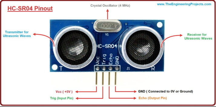
The ultrasonic sensor has four pinout. The pin at the edges are the Vcc(+5V) and ground (GND). The other two pins are the trigger (Input pin), which initializes the measurement and the echo (output pin), This pin goes high for a period of time which will be equal to the time taken for the US wave to return back to the sensor.
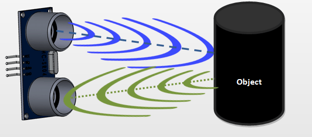
So based on the image above, the working of the ultrasonic is based on the reflection of the sound wave produced by the trigger pin. So by measuring the time for the wave to reflect back we can measure the distance covered by the sound wave.
Schematic And PCB Design.
To design this input design board. I used the eagle CAD software, because for this assignment I am using my old hello world board and improvised the schematic by adding 02x02 header pin to connect my ultrasonic sensor
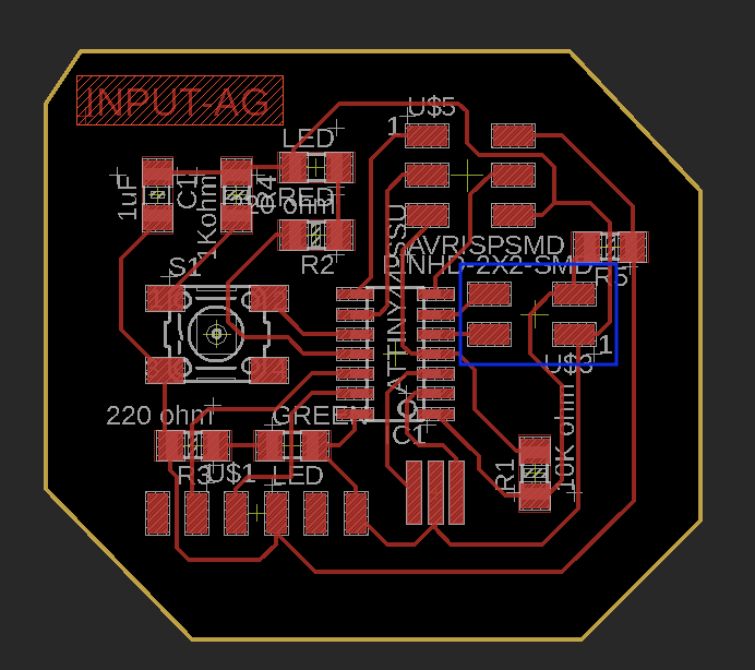
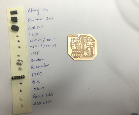
So this is my hello world board, which I had designed during the Pre-Fab Academy.
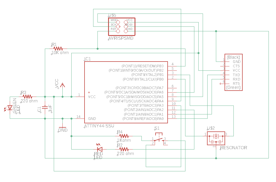
And the schematic shown below is my improvised hello world board for the input week.

The components used in this design are: - AtTiny 44. - FTDI Header pins. - 20 Mhz Resonator. - AVRISP. - 1uF Capacitor. - 0 ohm, 2nos of 220 ohm, 10k ohm, 1k ohm. - Red and green LEDs. - 2x02 header pin.
It was much easier to route this board since compared to my hello world board I just had to and 02x02 header pin to connect the ultrasonic sensor.
Milling the board.
Now to mill the board, its easier in eagle since we can easily export the PCB file in png format to generate rml files.
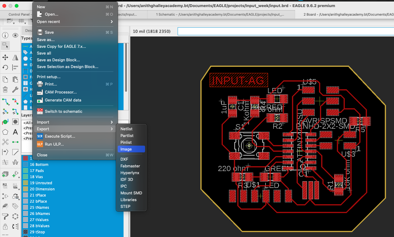
First select only the required layers, where Top layer for the traces and Dimension layer for the edge cut file.
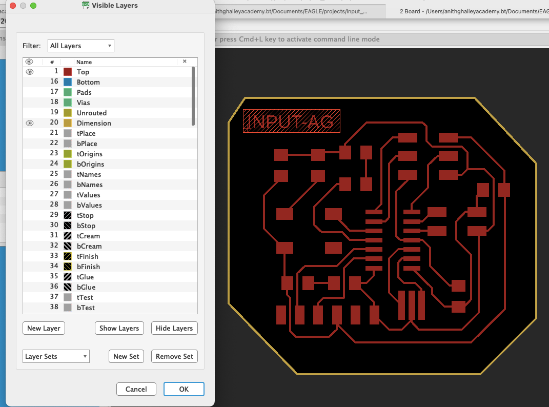
The png files are:
- Traces.

- Edge cut.

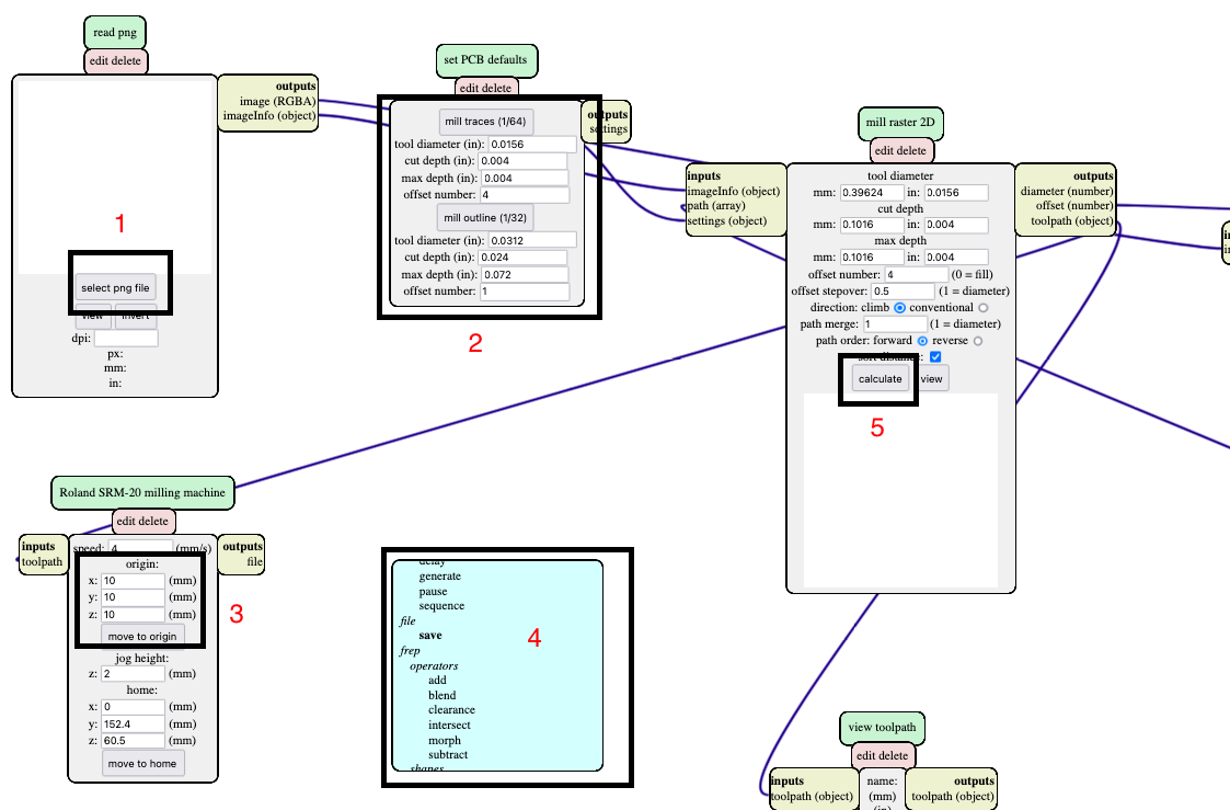
Noew to mill the PCB we have:
- Add the png file.
- Select 1/64 to print traces and 1/32 to cut the edges.
- Set the origin to X=0, Y=0, Z=0.
- And then Add the save file module.
- Finally click calculate.
Next we will use the Vpanel to cut the traces and edges of the PCB.
First we will use the 1/64 endmill and set the origin of the machine to the surface of the plate by zeroing. To cut out the traces we will add the traces rml file as output.
But there was some problem with the alignment of the sacrificial layer and hence all the copper plate were not traced.
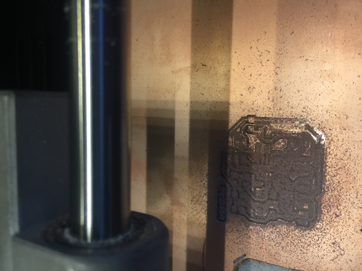
There for I gave another shot and kept the origin as same but adjusted the zeroing on the other side when traces were incomplete.
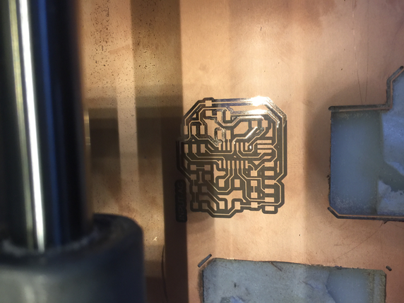
This method was good enough to complete the work. And now to cut the edges we will now use the 1/32 enmill, maintain the zeroing and add the edge cut rml file as output to the machine.
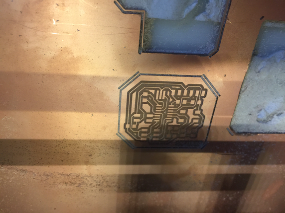
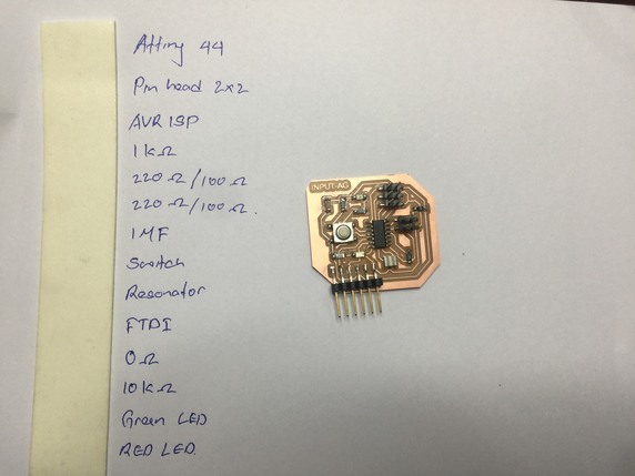
Finally the board is ready.
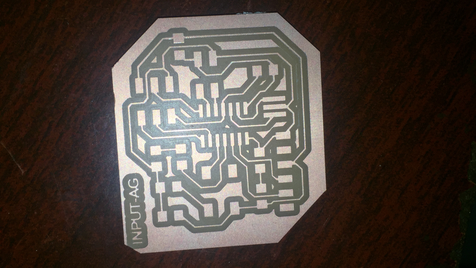
And now to complete the PCB all the components are assembled and the board is all set to be assembled.
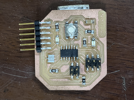
All the components assembled and the input board is ready to be programed.
Programming
So, now the ultrasonic sensor is connected to the 02x02 header pin and the pins are connected to followings GPIO pins.
Vcc - 5V
Gnd - Gnd
Trig -
Echo -
But before programming the board with the attiny45, I tested the sensor with arduino.

And the Sensor is working fine.
Next is to connect the Ultrasonic sensor with my board.
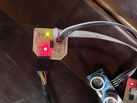
The program code used to interface can be found under files. I am able to get the distance out put.
Then I programed the LED to blink based on the input from the ultrasonic sensor.
if(distance <= 50)
    {
      digitalWrite(2,HIGH);
    }
    else
    {
      digitalWrite(2,LOW);
    }
And Its working.
Problem during the week.
I printed my first board and assembled all the components but I was only able to control the LED but the blink was not clear. This is my first board.
I took a multimeter and checked the connection and if there is any short circuit, There I found there was some unknow problem from the botton.
Took the soldering rod and tried to maintain a good soldered joints. But it was still the same. Then I desoldered the button and tested, It was working now.

The problem was from the botton.