4. Computer controlled cutting
This week has been quite hard to cover up the concepts and learning. Since due to lockdown, I was not able to access the lab till today. For this week we had to work on the the computer controlled cutting, Today we worked with the laser cutter and vinyl cutter. It was really a great fun working with the machines and creating something from our design work has always been great.
Task: Computer-Controlled Cutting
- Group assignment:
characterize your lasercutter’s focus, power, speed, rate, kerf, and joint clearance Document your work to the group work page and reflect on your individual page what you learned
- Individual assignments
Design, lasercut, and document a parametric press-fit construction kit, which can be assembled in multiple ways. Account for the lasercutter kerf. cut something on the vinylcutter
Laser Cutter.
For laser cutter assignement, I designed few construction kits which can be connected with the help of the slot designed on the construction kit.
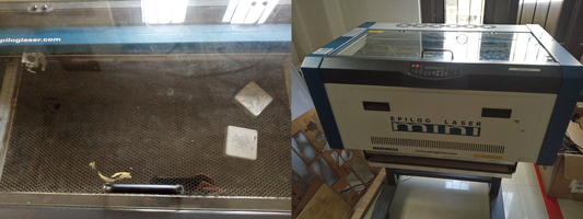
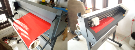
- The left image shows the bed of the laser cutter and the image on the right is the laser cutter used in the lab.
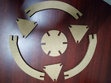
I used fusion360 to design the construction kit. For the first model I used the laser cutter to creat three triangle kit, one circle kit and three curve kit. I called the final assembled model as the Curved Tower.
Sketch of the presskit.
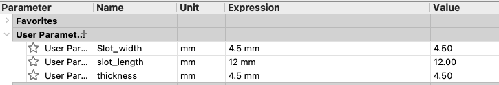
- Before creating a sketch of each press kit, first of all I added some user paramenter for slots and thickness. After the group assignment I didnt consider the kerf for my design since there was no significant difference. But kept the width of the slot to 4.5 mm for a 4 mm cardboard to avoid some fitting issues after cutting.
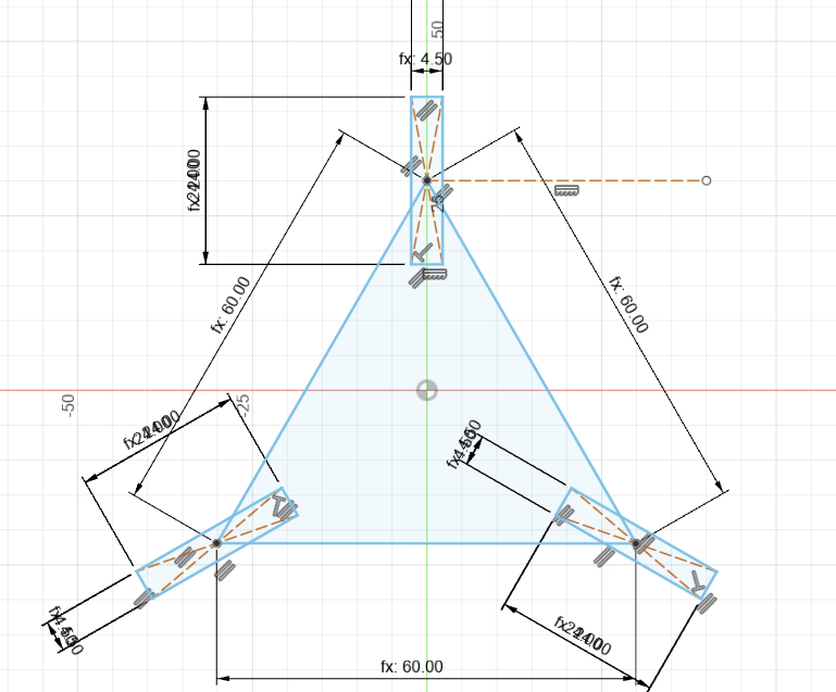
The Curve kit parameter.
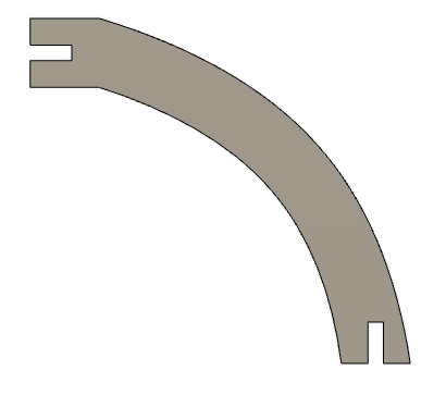
Te curve kit Sketch.
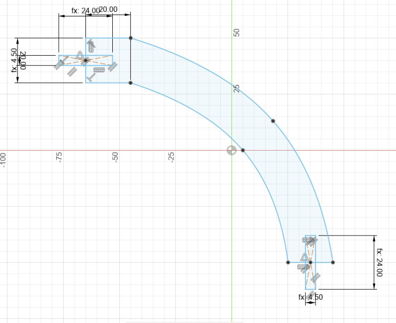
- The curve kit:
The Triangle kit parameter.

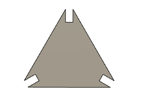
The Triangle kit Sketch.
- The Triangle kit:
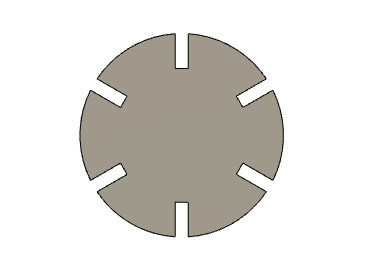
The Circular kit parameter: 
- The circle kit:
All is press kits were used to creat the model below: - The image of constructed model.
Before printing the construction kit, all the kits were exported in .dxf format. And with the help of this files the kits were printed and cutted on a 4mm cartoon box.
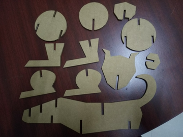
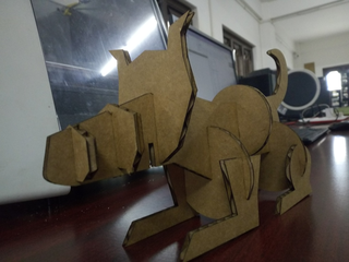
Also I also took the opportunity to creat a dog stucture using different types and shapes of the conctruction kit.
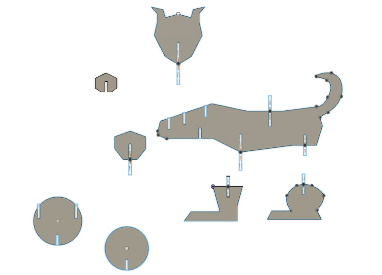
For this dog structure, I didnt used an proper length of the slot but my parameters were constant slot width i.e 4.5 mm and the slot with would be multiple of 12 mm based on the location of the slots.
I used the coral draw softaware to command the laser cutter to cut out the presskits. I used the fusion360 to design the kits. I used the .dxf files exported from fusion360 and imported it to coral draw. The size of the printer is 609.6x304.8 and this set on the printing properties.
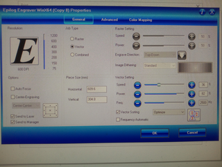
The settings kept to perform the operation are: 1. Power : 82 %. 2. Speed : 30 % 3. Frequency : 2500 Hz. 4. Auto Focus turned on.
Before we start to print we have to set the home coordinates for X and Y on the printer
The image below shows the output of the presskits using the laser cutter. - the image below presents the construction kit to make a dog.
- The image below presents the construction kit to my curve tower.
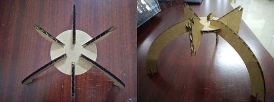
Finally the assembled model for the laser cutter assigments is given below.
- The Curve Tower.
- The Dog.
the slot on the designs were made paramatric in the design. so that the design can be edited easily.
Vinyl Cutter
We were also introduced to the vinyl cutter machine, where we can make stickers. I used the png image from the week two assignment. Which is a logo designed for my final project.
- Roland CAMM-1 GS-24.
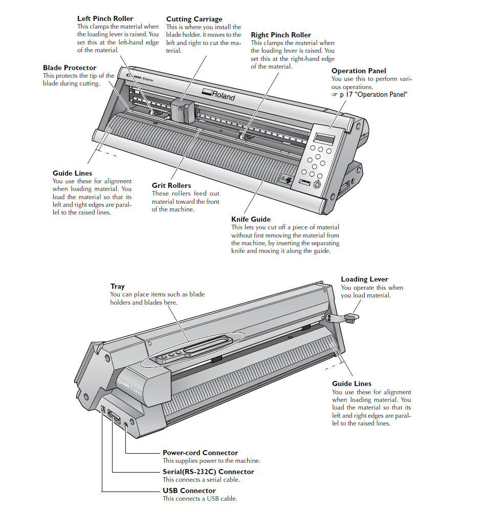
The image below gives a very good view of each parts of the vinyl cutter.
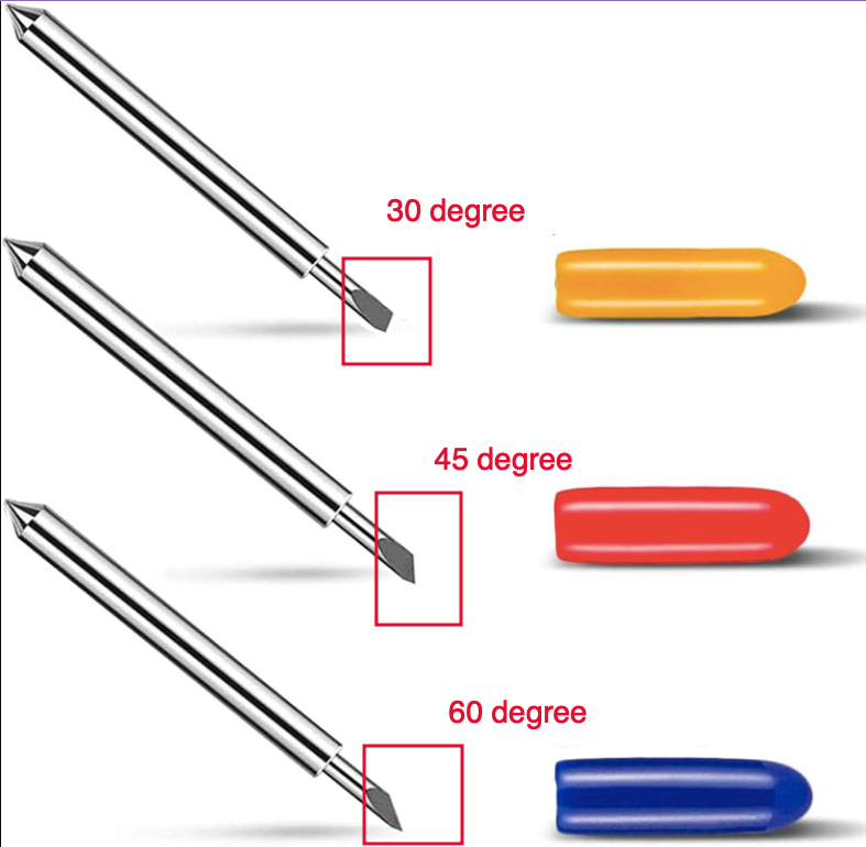
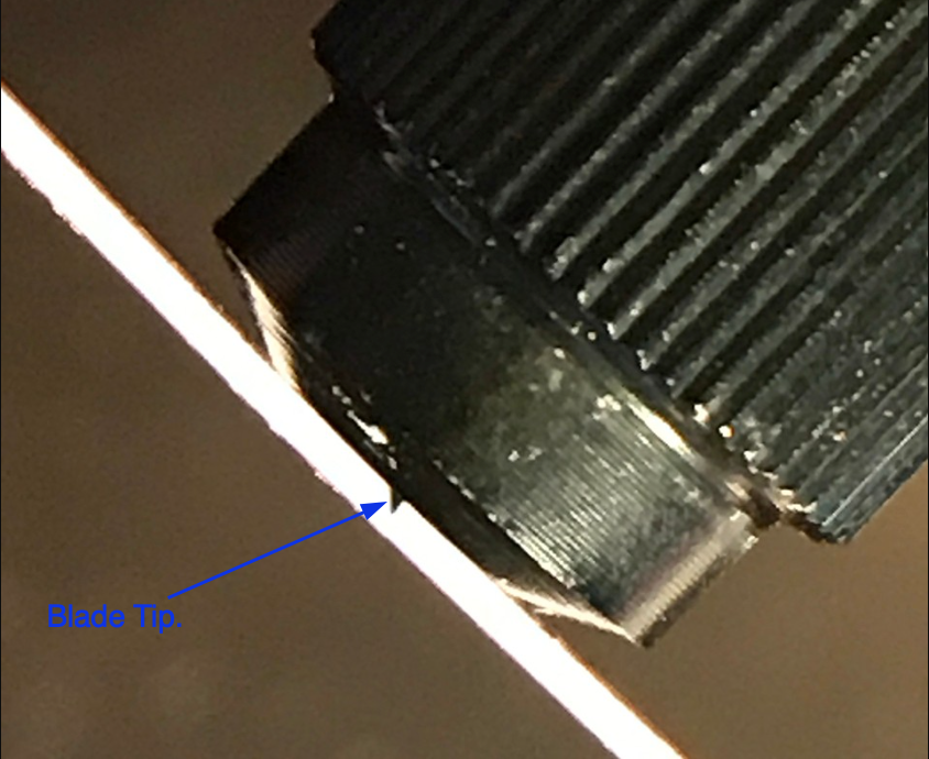
Our instructor demonstrated working with the vinyl cutter. There are 3 types of cutting blades and they can be differentiated based on the angle of the blades tip.
The blades should be adjusted in such way so that the blade will cut only the sticker layer.
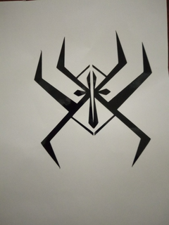
During the week two assignment on the 2D and 3D Designing week. I created a a logo for my final project. The image given below shows the image.
![]()
The image was converted to pdf since I was not able print using the svg format, therefore I converted the format to pdf and used the easy cut machine software to print the sticker.
- The image below is the screenshot of the pdf file.

- But I was not able to print my name using the vinyl cutter.
The software used for this machine is Easy Cut studio, Following settings were kept: - Cutting Force 30 gF - Speed 20cm/s
The blade used for this case was the blade with an cutting angle of 45 degree.
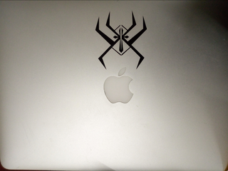
The image below shows the printed sticker on my laptop.
Group Assignment
Laser cutter.
I wanted to check the different settings of the laser. So at first, I maintained speed to 50% and kept varying the speed. And during the second time I kept the speed to 50% and varied the power of the laser.
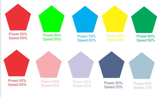
The image below shows out put on the rubberhood. We were not able to observe much difference with constant speed and varying power but when power is constant and speed is varied, we can observe the difference as shown below.
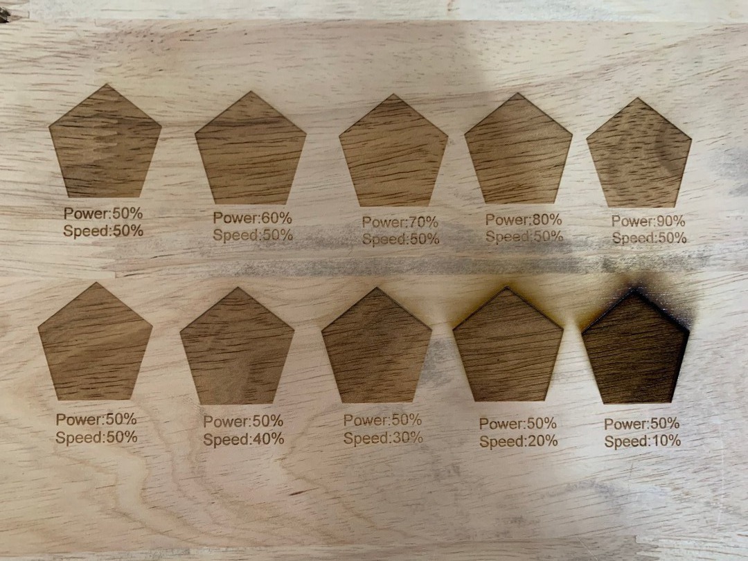
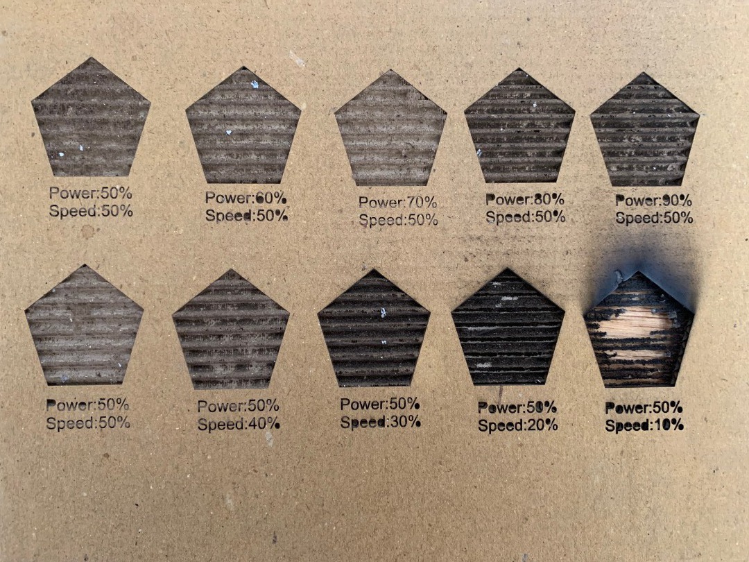
But when this same settings were made on a cardboard we can observed a good range of difference as shown below.
For the group assignment, we tried to check the kerf setting of the laser cutter. So that we would be able to check the accuracy of the laser cutter.
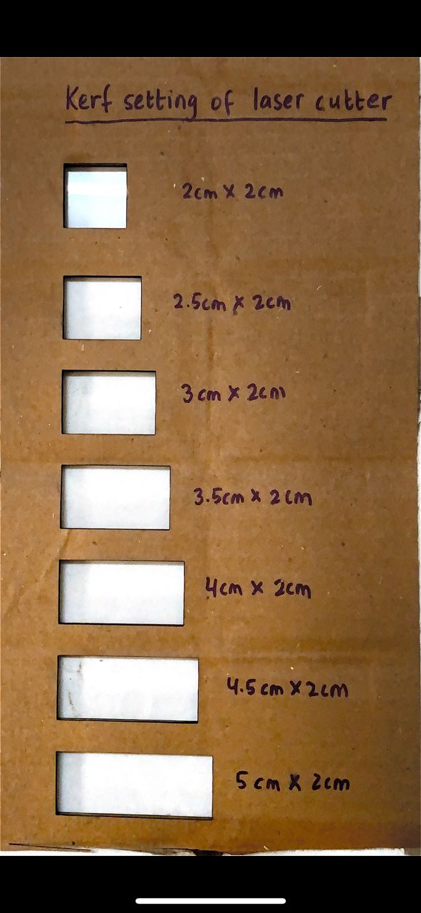
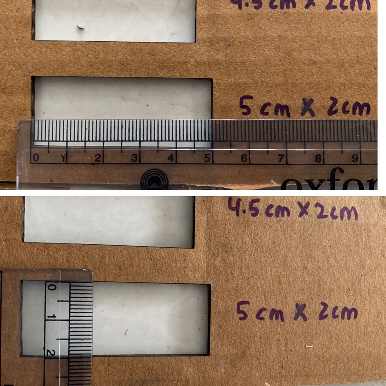
- Since the vernier caliper was having some battery problem, then we used a ruler to check the accuracy of the file.