3. Computer Aided design
This week we were introduced to various 2D and 3D softwares. We had to try these various software and pick one software for 2D design and one for 3D design. For 3D, I chosed Fusion360 because a lot range of tutorials are availabe and for 2D inkscape for the same reason.
2D Design:
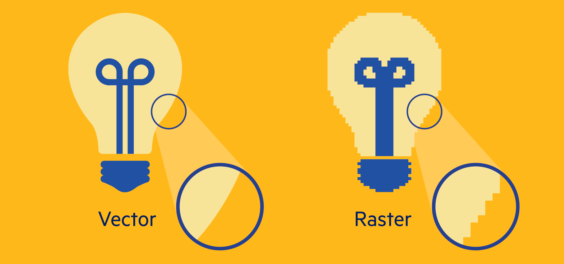
- The output format of 2D Design is either a Rastor or a vector Image.
- For machine we use vector images because it gives very good path for the machine to execute cut.
Vectorizing an image:
- The Software used is inkscape:
- Inkscape is a free and open-source vector graphics editor used to create vector images, primarily in Scalable Vector Graphics format.
I chosed inkscape to work on with the 2D design related work. To get a taste of the platform I First drew a sketch to create a logo for my final project.
![]()
Then I followed the tutorial video given below to design a logo. Whenever I had a changed of mind for the design, I went over the internet to learn how execute the design.
I took the sketch to my laptop and imported it to inkscape so that I can make a good outline of the logo.
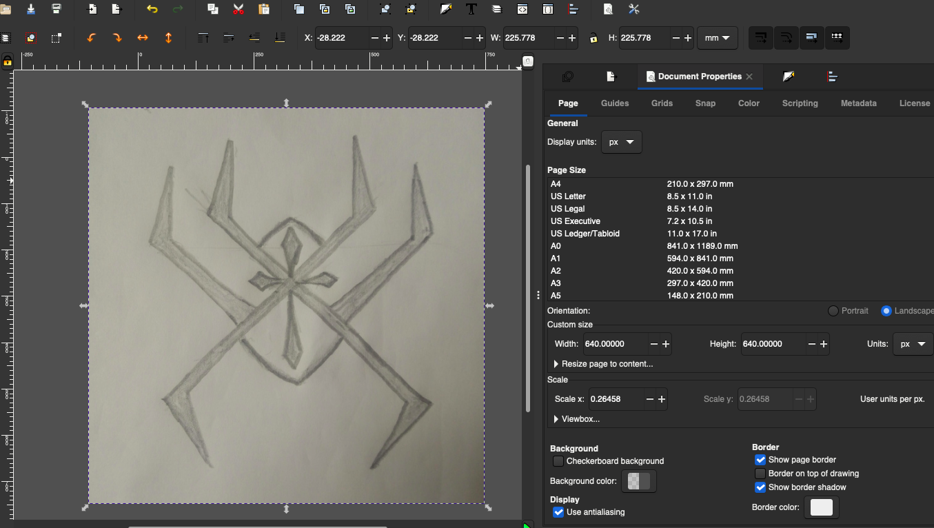
Since my logo is symitrical therefore I pen down straight lines for only half part of the sketch.
![]()
Then with the help of the feature from path effects I mirrored the outlins to create my complete logo.
![]()
Then with some fill effects and colouring of the outline stockes. The Final output of the design is given below.
![]()
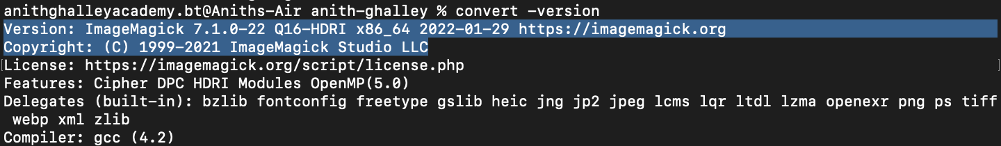
Installing Imagemagick:
Imagemagick is an CLI tool to perform image editing in a very fast and efficient way. - Command used to install imagemagick:
brew install imagemagick
And then I learned that we can create a temp forlder and for time being we can dump all the documentation related images and use imagemagick to perform various image editing process. - The folder will be listed in .gitignore, so that whenever I push my repo the temp file will not be ignored.
Command used to open the .gitignore is:
nano .gitignore
This will open a new terminal where we can add add the types of files and folders we want git to ignore while pushing the repo.
Task Performed Using Imagemagick.
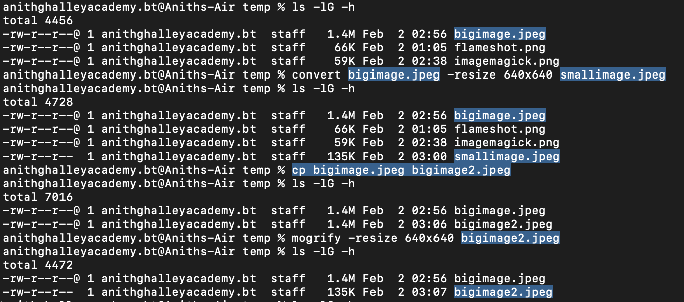
Command used to get the detailed list of the files and folder present in the home directory for mac is:
ls -lG -h
- REsize the image and creat a new one with compressed size.
convert bigimage.jpeg -resize 640x640 smallimage.jpeg
- Resizing the image to a particular resolution and replace the previous file.
mogrify -resize 640x640 bigimage2.jpeg
- Converting an image format.
magick bigimage2.jpeg bigimage2new.png
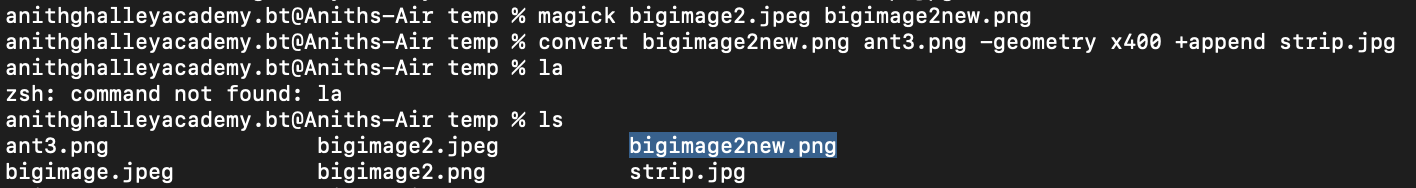
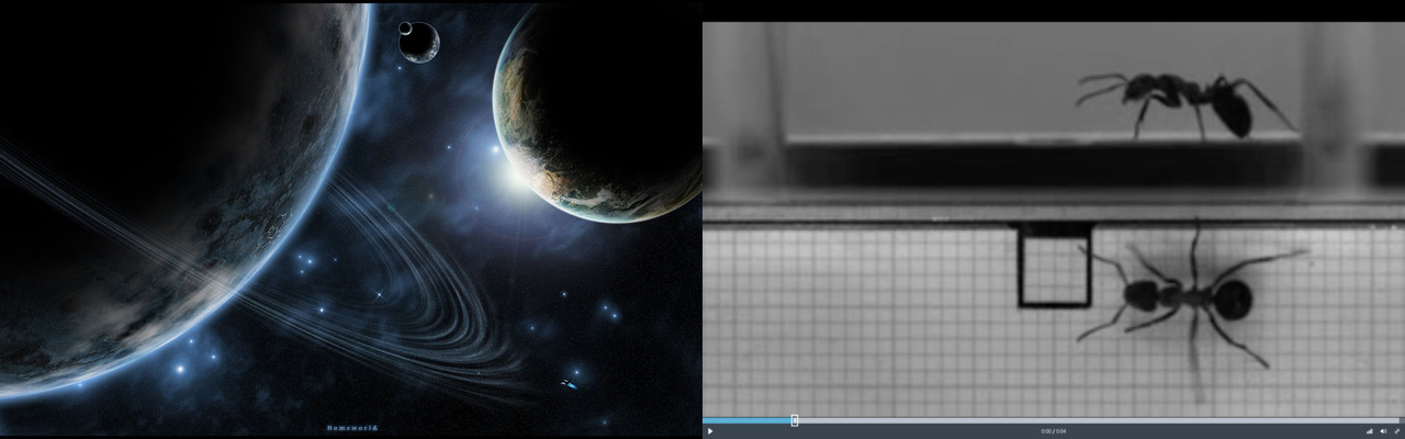
- Creating a compose image, using two image and generating one file with the two images side by side.
convert bigimage2new.png ant3.png -geometry x400 +append strip.jpg
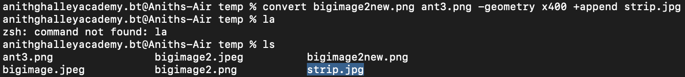
- The generated image:
GIMP
Just to explore more on more of 2D design software, I tried to edit and work on with the gimp software.
- So I took two images, and merge the two images together to make one image as the forground and other as the background.
The first I used is the image of our His Majesty The King. Which I wanted to keep in the forground of my output image.

And the second image is the image from Dochula Pass, it is one one of the pass in Bhutan, which is 3,150 meters above sea level.

I used the Gimp software to merge ge the image together, The output size of the image was 1.5 Mb, so I used the imagemagick to reduce the size of the image.
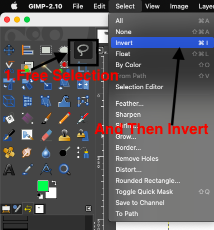
To crop merge th two image, I used the free select tool to creat a selection of own, And the inverted the selection. Next is to press Ctrl+X. Only the selected area will be visible.
The two images were imported to a common file and merged.
- The image shown below is the output using the Gimp Software.

When GIMP is compared with Imagemagick, I felt comfortable with imagemagick since it is super fast and saves a lot of time. However GIMP offer a graphical user interface hence giving option to customize the work. Therefore I would prefer to use both.
3D Design.
Onshape
Onshape is a cloud-based computer-aided design (CAD) software. Using web-based servers, software users can collaborate on a single model, editing and interacting at the same time.
I was very excited when I saw that we would also get an access to a cloud based 3D design software called Onshape. There for I went on with internet to try onshape.
I followed the tutorial to try out the Onshape.
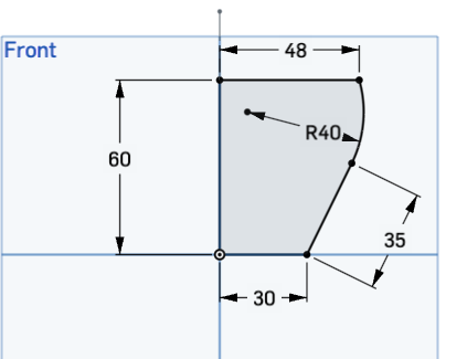
To start we I made a new sketch to design a coffee cup using onshape. The image below shows the dimensions of my sketch.
Then to create a structure, I tried to made the dimension to revolve my drawing.
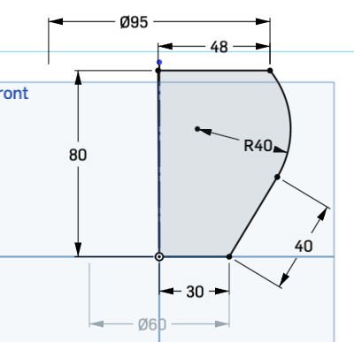
Then an offset sketch is created, so that I would able maintain a wall structure of the cup.
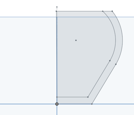
After the dimension was set, the the revolve function was used to create solid coffee cup solid model.
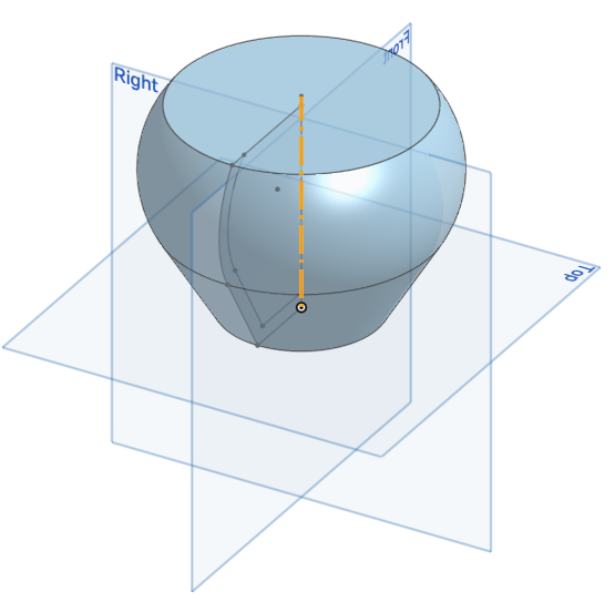
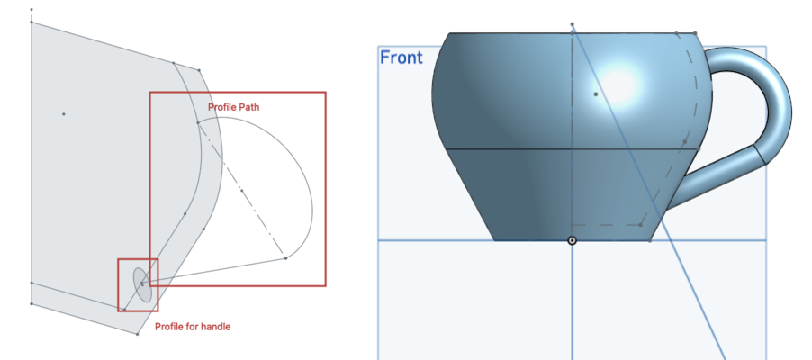
And then a path and a profile is created to generate a the handle of the path. The image on the left showes the profile and the path to sweep and generate the handle as shown on the right side of the image.
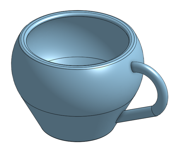
After that the revolve feature is used again to create a hallow space inside the cup. And then fillet feature is used to make a curve smooth on the top and bottom edges of the cup.
- I found uncomfortable in onshape to go back and edit the past sketches. And also fusion provides the timeline feature to look back and edit our work at any point of time.
Fusion 360
To refresh my understanding for fusion360, I watched a video given below.
Since I had already installed fusion360 in my computer and I wished to work on with fusion360, because it has a huge community and tutorial for me refer.
The 3D Design.
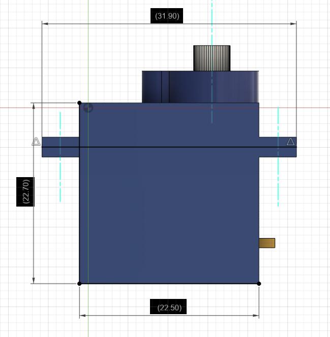
I wanted to design the robotic limb of my spider. Therefore I First importated a open source micro servo model to use it as reference to design the rest of the components. - The open source 3D model are all downloaded from GrabCad. - Sketch to create the servo one joint, which will be connected to the servo on the body of the spider. - The dimensions of the servo is:
View 1:
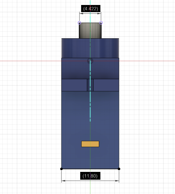
Viev 2:
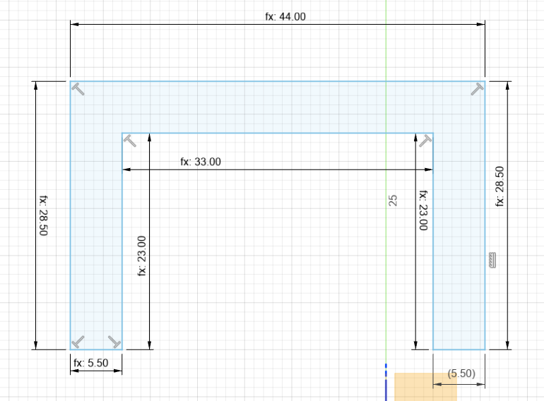
- The basic sketch to start designing is shown below with reference with the servos dimension. Based on the dimension of the micro servo motor, the parameters were set and the image below shows the basic dimension defined to design the limb.
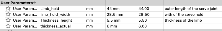
Based on the above parameters, a servo holder sketch is made as shown below.
- Based on the dimensions of the servo the design below is made to connect the servo with the linb.
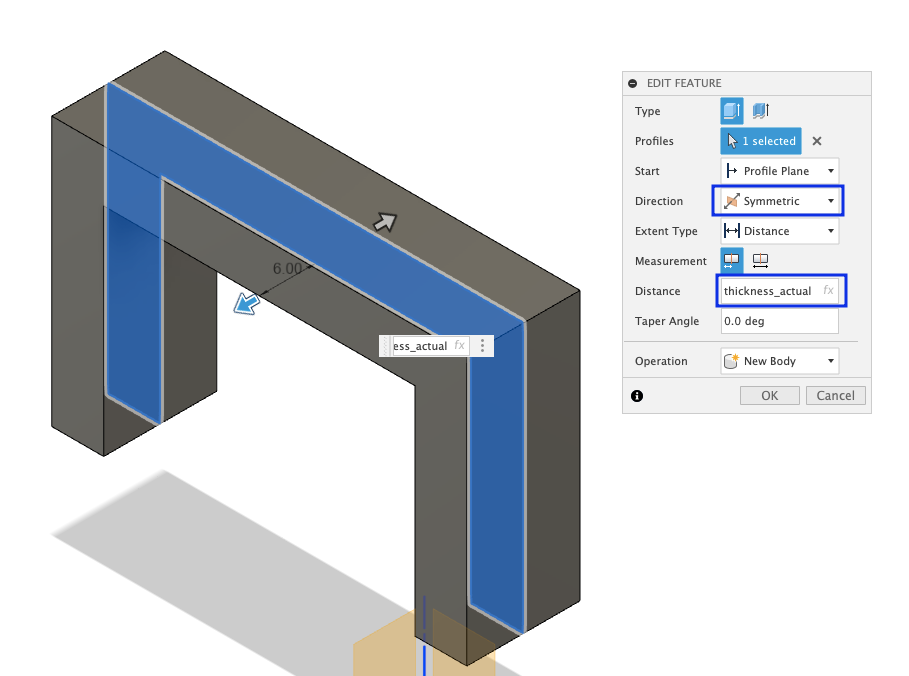
The design of the lower limb connected to servo one is shown below. This servo will be connected to the body of the robot. This servo will give forward and backward movement for the limbs.
- Designing the second part of the limb (the second end of the limb).
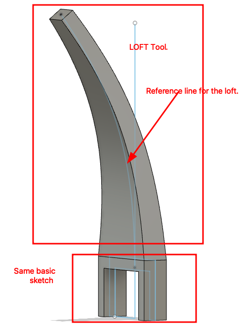
- The same basic sketch and servo is used to create a connecting joint for the servo 2.
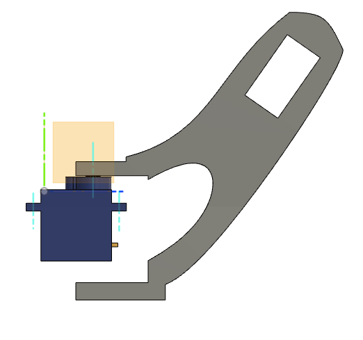
- A curve line is extended from the basic servo hold design to create a loft along the curve line, so that the curvy limb can be creted.
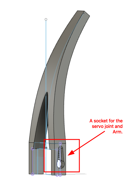
And then a socket for the second servo to connect with the limb is made. The Arm will be responsible from maintaining the movement of the Limb.
Joints.
It was time for assemblimg all the components together. There for I checked the video tutoril below to learn and manage joints in fusion360.
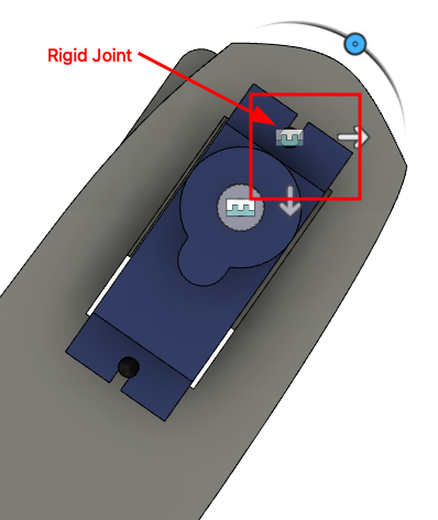
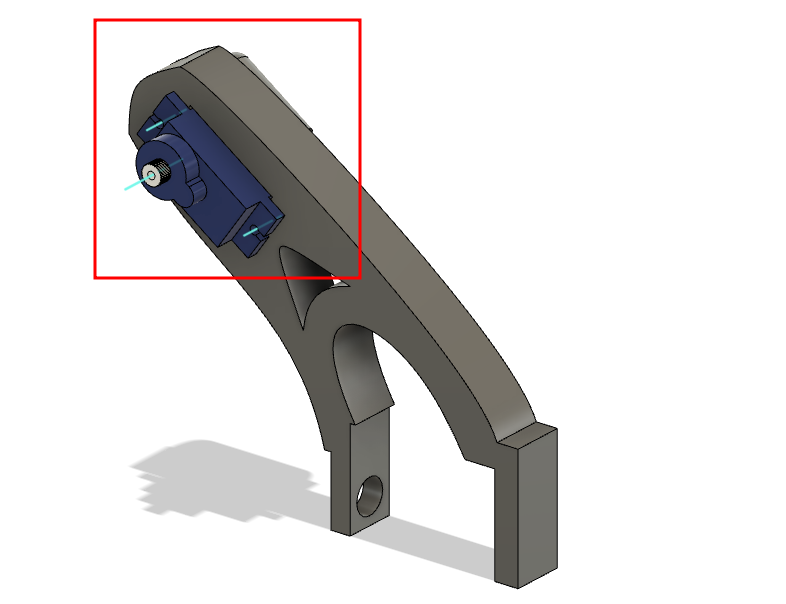
- First a 2nd servo is inserted at the top of the first limb as a rigid joint (so that it stays fixed).
Then another joint is created between the second limb and the servo arm, so that I can be connected with the second servo.
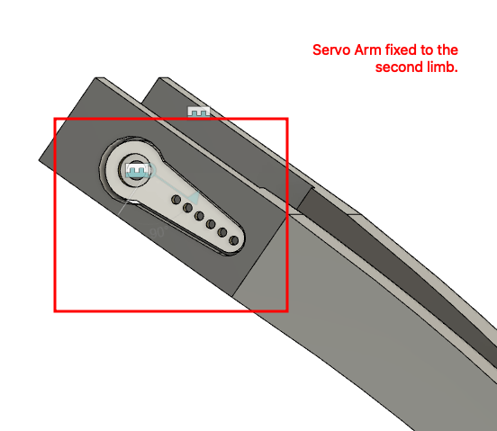
This will bring us to conncect the two limbs together where the pivoted point will be on the gear of the secend servo. - Similar rigid joint is made for servo one as well. - Connecting all the components together.
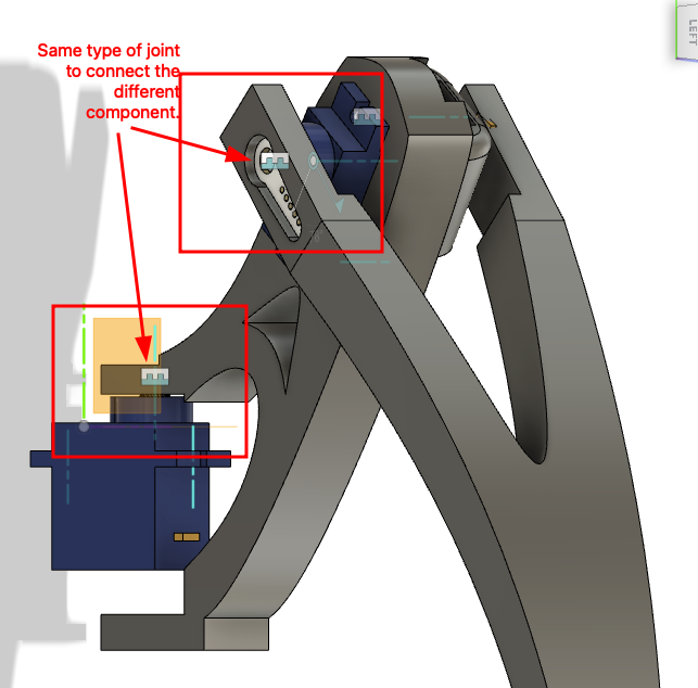
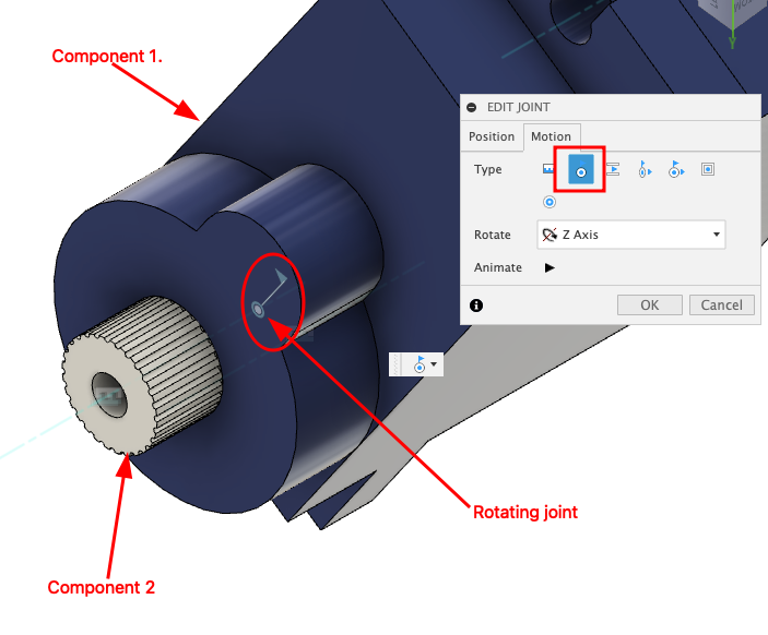
All other joints are rigid except for the joint between the servo model and the rotating gear where the servo arm will be mounted.
- Animation and motion study video is attached below.
When I was trying to sync the two joints, only of the joint was working at a time. Therefore after looking over in the internet it was solved by removing the rigid joint between the top servo and its frame. The two components were supposed to made as a rigid group so that it would follow along with the joint movement.
- After this all the joints started to work fine.
Model
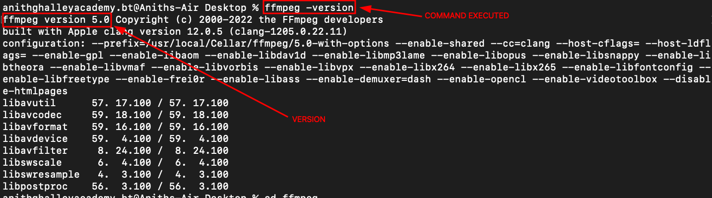
Video Editing and Compression
For the video editing and compression I downloaded ffmpeg using homebrew. - The command to istall ffmpeg are:
brew tap homebrew-ffmpeg/ffmpeg
brew install homebrew-ffmpeg/ffmpeg/ffmpeg
 While designing the project in Fusion360, I made recordings of motion study and an explosion of the components animation.
- ffmpeg command to play a part (Eg: 00:00:02 to 00:00:10) from a video.
ffplay -i animation.mov -ss 00:00:2 -t 00:00:08
Both the videos are trimed and two new videos are created. - ffmpeg command to trim a video (Eg: 00:00:02 to 00:00:10) used:
ffmpeg -i animation.mov -ss 00:00:2 -t 00:00:08 -codec copy animation_clip.m
 - filename_clip.mov are the trimed video using ffmpeg.
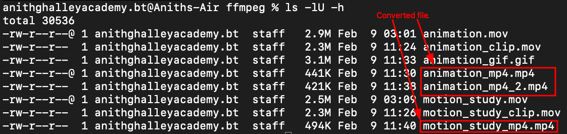
Since the video format was in .mov extension and the size were in megabytes, Therefore using ffmpeg the videos were converted to .mp4 extension compressing the file fro 2.4 Mb to 430 Kb.
But the problem here was that the file size is still about 400kb. Hence From Rico, he shared a command to use ffmpeg to preserve the quality and compress the file size. The command used is:
ffmpeg -i <input file> -c:v libx264 -crf 24 -preset slow <output file...mp4>
To understand the command:
- c codec (a:audio v:video)
- crf is the quality, lower means better quality, 15-25 is usually good
-
preset The range of the CRF scale is 0–51, where 0 is lossless, 23 is the default, and 51 is worst quality possible. A lower value generally leads to higher quality, and a subjectively sane range is 17–28. Consider 17 or 18 to be visually lossless or nearly so; it should look the same or nearly the same as the input but it isn’t technically lossless. The range is exponential, so increasing the CRF value +6 results in roughly half the bitrate / file size, while -6 leads to roughly twice the bitrate. Choose the highest CRF value that still provides an acceptable quality. If the output looks good, then try a higher value. If it looks bad, choose a lower value.
-
A preset is a collection of options that will provide a certain encoding speed to compression ratio. A slower preset will provide better compression (compression is quality per filesize). This means that, for example, if you target a certain file size or constant bit rate, you will achieve better quality with a slower preset. Similarly, for constant quality encoding, you will simply save bitrate by choosing a slower preset.
The coverted videos for motion study and components explosion are attached below:
- Motion Study Video:
- Components Explosion Video: