6. 3D Scanning and printing
This week was about 3D printing and scanning learning experience for me. I have always been excited about 3D printing and printer. There are two types of manufacturing a 3D model and they are additive and subtractive processes. The main difference between additive and subtractive manufacturing is explored for this week.
Task: Computer-Controlled Cutting
- Group assignment:
characterize your lasercutter’s focus, power, speed, rate, kerf, and joint clearance Document your work to the group work page and reflect on your individual page what you learned.
- Individual assignments
Design, lasercut, and document a parametric press-fit construction kit, which can be assembled in multiple ways. Account for the lasercutter kerf. cut something on the vinylcutter
Manufacturing Processes.
In additive manufacturing process. The building up of the model is done by depositing the material layer by layer. This enables us to access the inside and outside areas of a enclosed or nested parts of a design.
The diagram below clearly shows the manufacturing approaches of additive and substracting manufacturing processes.
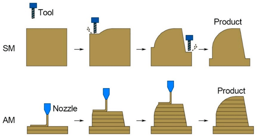
In subtractive manufacturing process, materials are removed from a solid block to get an output of a required shape.
Comparing subtractive and additive manufacturing processes, the waste material generated by substractive process is more compared to the additive process.
For additive processes, there is a range a ways the process can fail wasting time and materials. It takes significanting more time compared substractive process. Therefore it is very important to check the design rule of the 3D printer so that basic sesolution of a machine is known before printing a model.
3D Design.
To design a model, I used fusion360 software to generate a model to 3D print it.
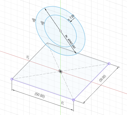
First a square model was created and the two different sized rings were placed on the extruded square and align those rings 45 degree from the surface of the extruded square.
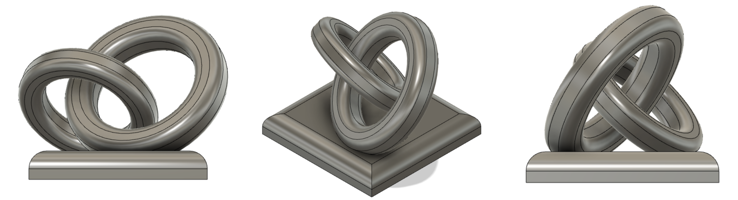
The image above shows the front view, isometric view and side view of my design.
The parameters set to design the model are shown below.

The parameters defined in the design are applied as shown below.
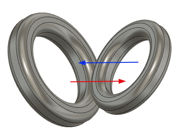
The design which makes the above design most suitable for additive manufacturing are the interlocked rings. As per the outcomes from the group assignment the 45 degre would led to formation of strings of filaments hanging and supports will be required.
The video below showns a quick visual of the steps taken to design the model.
The inclination of the rings make this model to be printed through the additive printing process only.
The viewer below presents the model.
Printing.
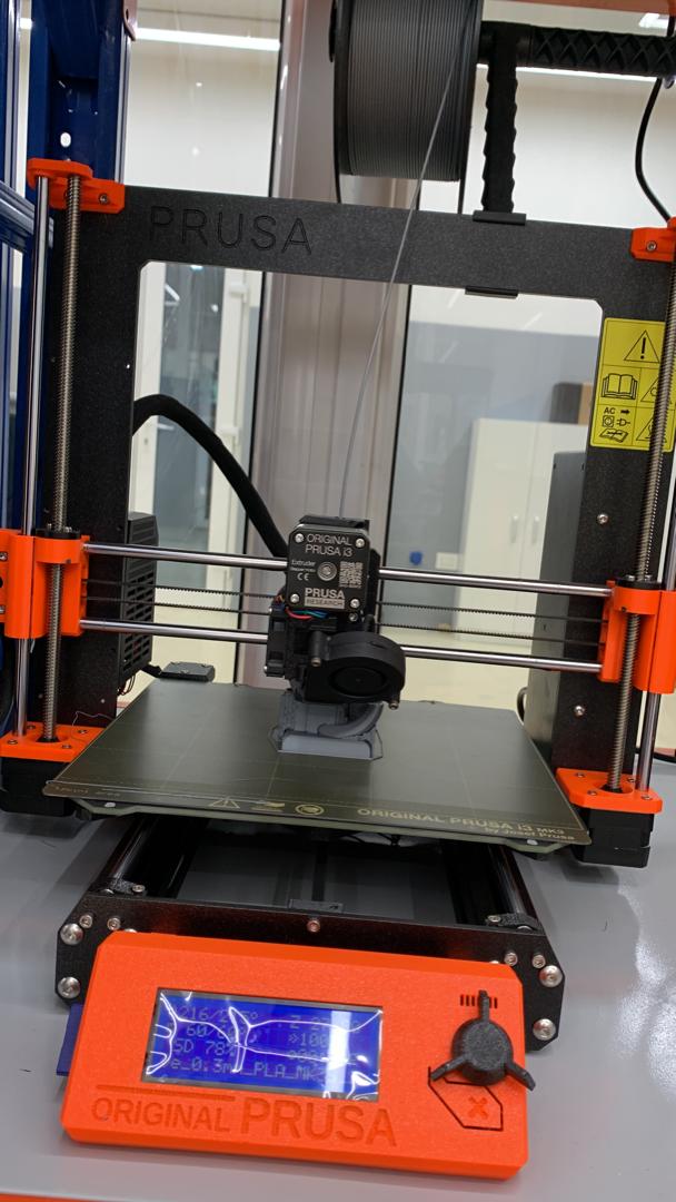
The machine used to print the model was Original prusa 3D printer.
Using the prusa slicer to convert the stl format to G-code format. And then the g-code file is then put in a SD card which is then inserted to the 3D printer and then it prints the design.
- The stl file is imported to the machine software to generate the g-code.
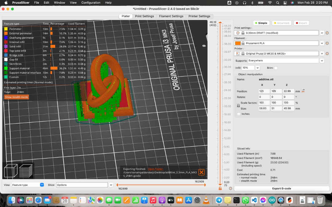
Supports were required to be added while generating the g-code because to the two rings in my design are leaning at an angle about 45o with reference to the horizontal plane.
The g-code generated is taken to the printer using the SD card and the file will be selected from the display and print command is provided to start printing.
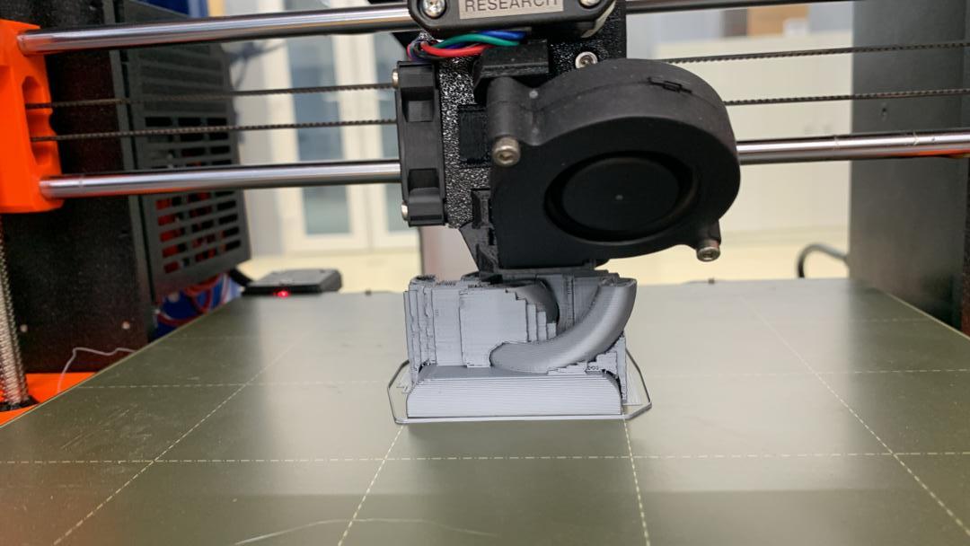
After the printing is done, the model is left with supports as shown below.
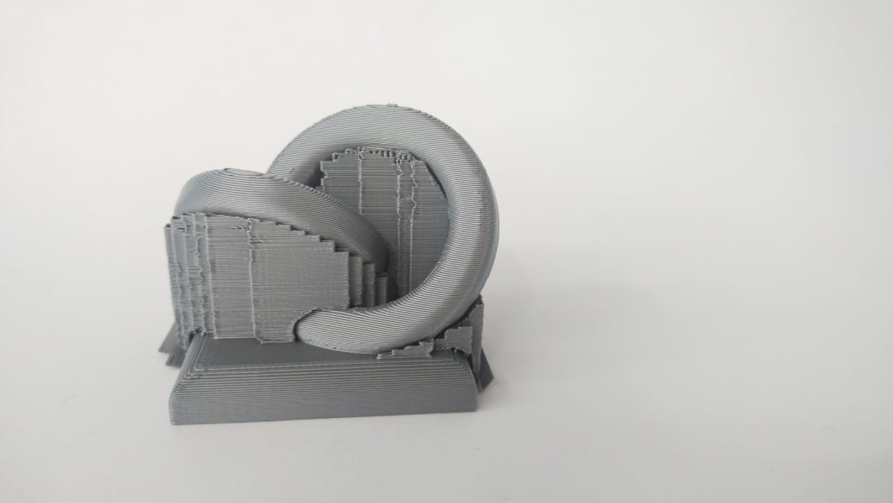
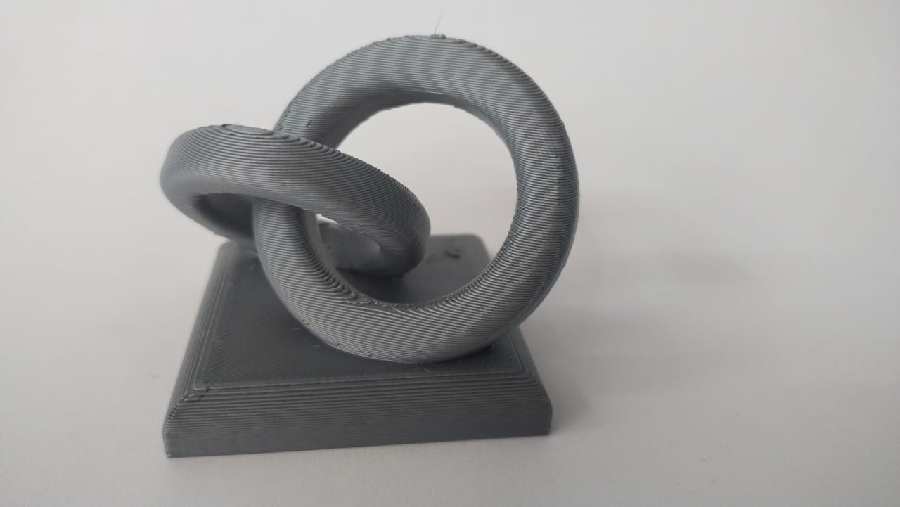
And finally, the supports are removed and the final output of 3D printing is:
Why additive manufacturing for this design?
The model represents two different diametered rings entangled together, Therefor it would be hard for the substractive process to complete the model as compared to the additive process.
3D Scanning.
Since due to the covid, most region of the country were under lockdown. And therefore I was unable to do the 3D scanning assignment for this.
3D scanning is a process of analyzing an object from the real world, to digitally collect the data of an objects shapes, appearances and features.
The Scanner I used for this assignment is the Revopoint 3D scanner.
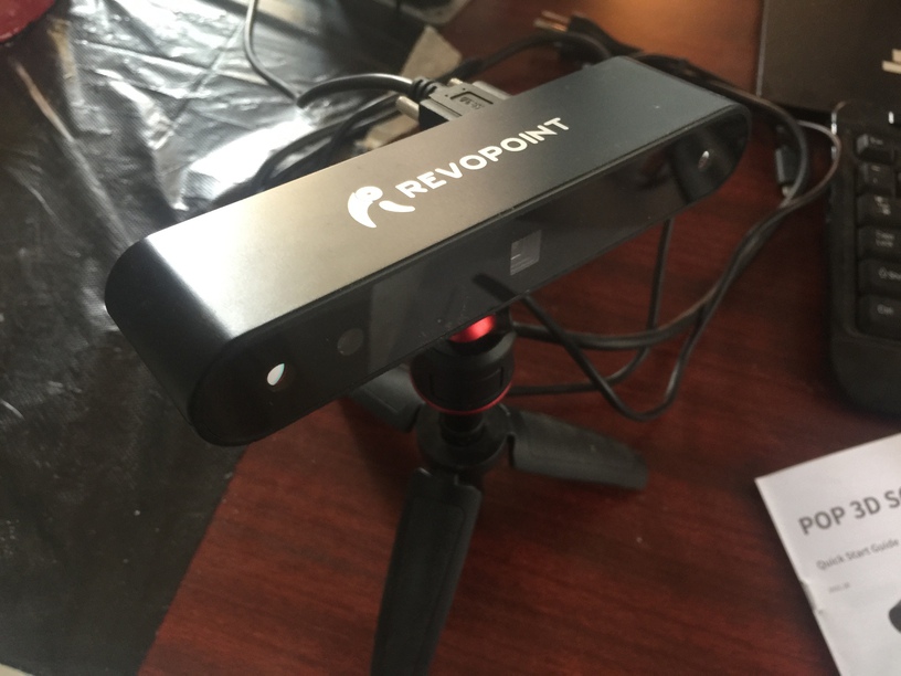
And the software used to generate the 3D model of an object is the Revo Scan. The Revo point scanner has the accuracy upto 0.3mm and multi scanning modes feature.

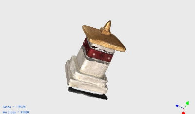
First we connect the scanner to the computer and open the revo scan. And click on new scan. I scanned the small stupa which is shown below.
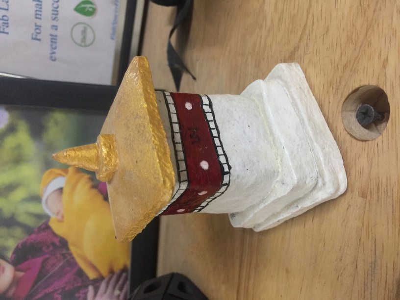
And the output after scanning is.
Group Assignment.
Models
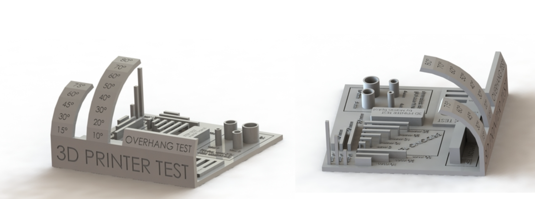
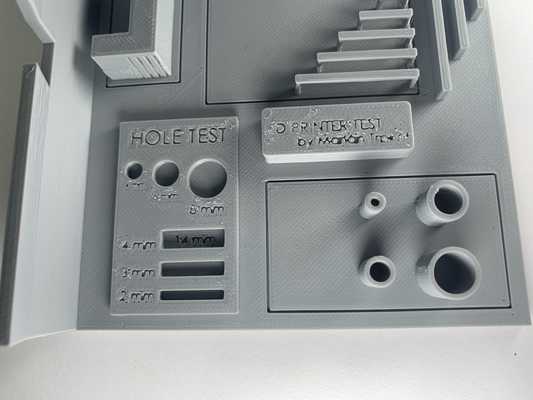
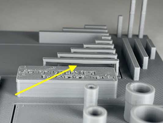
Different 3D printing processes have different capabilities and different design restrictions.Anything can be “drawn” in 3D on a digital canvas, but not everything can be 3D printed as in the digital design environment, there are no laws of physics to adhere to, such as gravity.
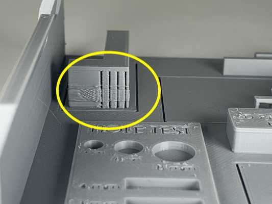
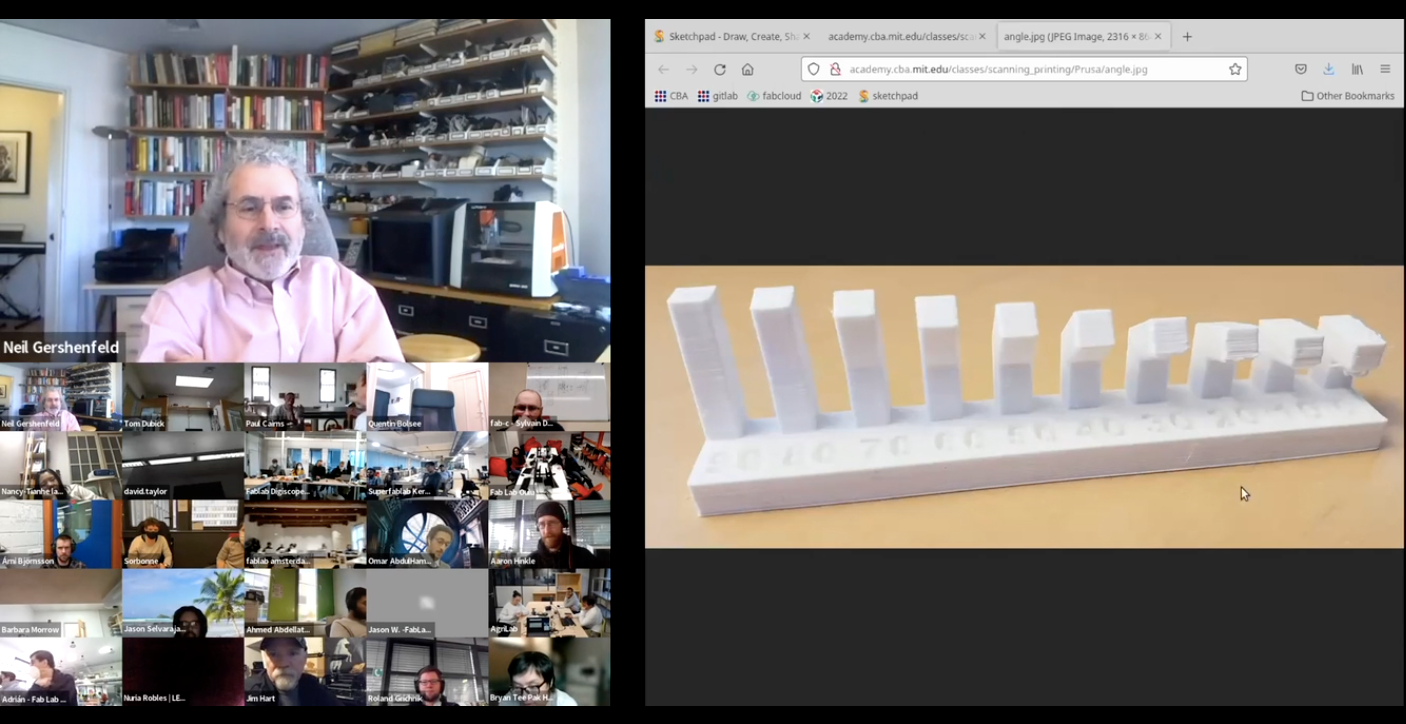
For the group assignment, we had to test the design rules for your 3D printers. So we chose a design where there are overhangs at different angles, bridging test, hole test, etc
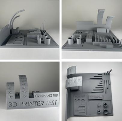
The Results
Comments.
- The overhangs after 60 degrees has strings of filament hanging
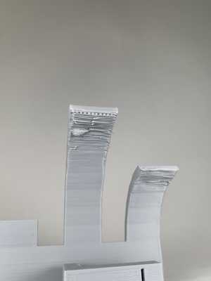
- The finer details were not printed well
- The bridges were hanging.
- Even when we used 0.15mm layering height, the layering were not so good.