16. Interface and application programming
This week was about learning how develop an interface of a device and write an application for the user. The application must be able to control input or output of a controllor. Neil introduced us to various different ways and languages to develop an interface for input and output devices.
Task: Interface and Application Programming
- Group assignment:
Compare as many tool options as possible.
- Individual assignment
Write an application that interfaces a user with an input and/or output device that you made
Group Assignment.
The group assignment can be found here
MIT App Invetor.
So to start up with designing and develop my application for my final project board. I started with the MIT App Inventor because after fabacademy, I will be going back as a teacher and I found the app Inventor very interesting for me to introduce my students with this platform.
Therfore, I created my account on the platform and started to explore the platform.
Basically the layout of the platform looks as shown below.
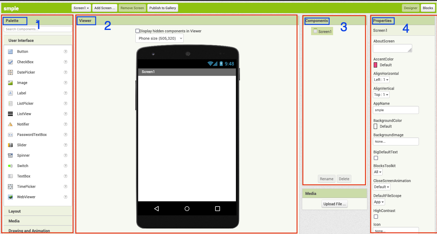
- Palette : From this section, we can add functions and features to the app.
- VIewer : This area will show the realtime of our app.
- Components : This part will hold the layout and coomponents used in the app.
- Properties : This section gives option to edit the components added in the app.
On the top right cornor, the platform enables the user to navigate between the designer and blocks tap.
- Designer Tap : This tap provides and support features and options to work on the look and fill of the app.
- Block Tap : This is where we write the underlying logics and instructions for the app the function.
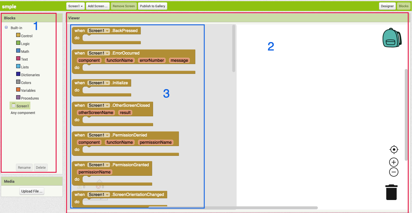
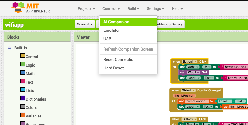
The image above showes the interface of the Block tap, where we develop the code for the app. 1. Blocks : Blocks holds the code blocks for some built-in and user defined components. 2. Viewer : This will be the working space to arrange the codeblocks. 3. When any of the built-in or user defined components are selected, certain code block linked with the components are shown.
I followed this video to learn on developing an application to coltrol a LED on my board connected to GPIO4 of the ESP32 WROOM 32.
The image shows the LED to be controlled by the app over the WiFi connection on the ESP32’s local IP.
I will be using the same board that I fabricate during the networking week.
APP
First I created a project in the Mit App Inventor, and added the components as per the apps requirment as shown below.
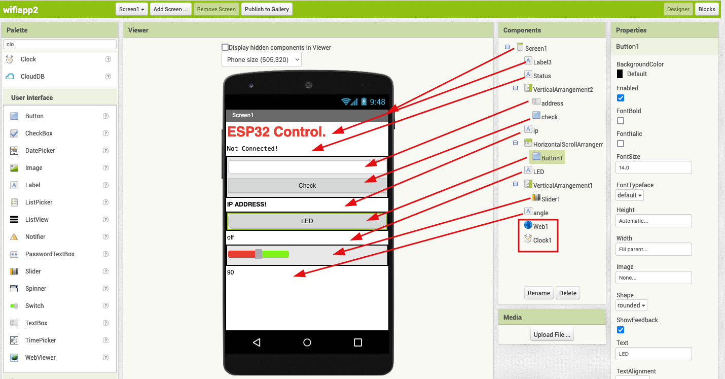
THe two modules in that red square are web and clock.
- Web to connect to the wifi.
- Clock to transmit the signal.
LED Control.
- To control the LED, I used two buttons to turn on and turn off the led respectively. When ever a button is pressed the expected status of the the LED is shown below the buttons.
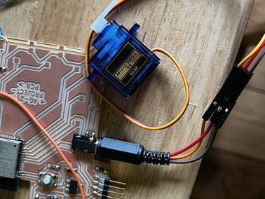
Servo Control.
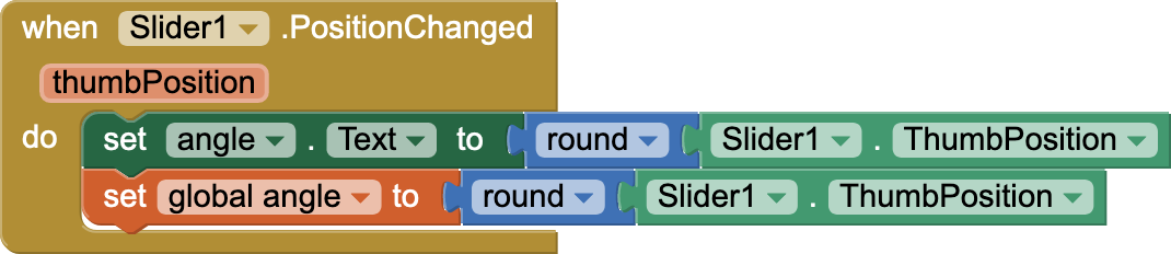
- To control the servo, I used a slider to generate a value between 0 to 180. Based on the thump position of the slider the value is selected and when the send angle button is pressed the value is sent to the ESP32 board over the wifi.
The code blocks for the app is shown below.
To connect to the board, an ip address of the board will be entered in the app and wheck check botton is pressed the app will starte communicating with the board. The block below explains the flow.
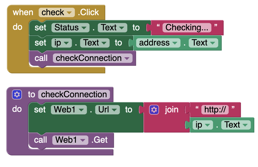
and the communication between the board and app is maintained by the following app.
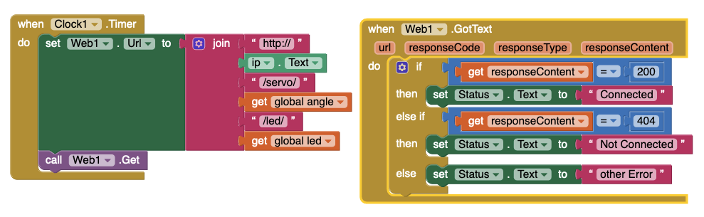
This block is responsible of maintaining the on and off status for LED.
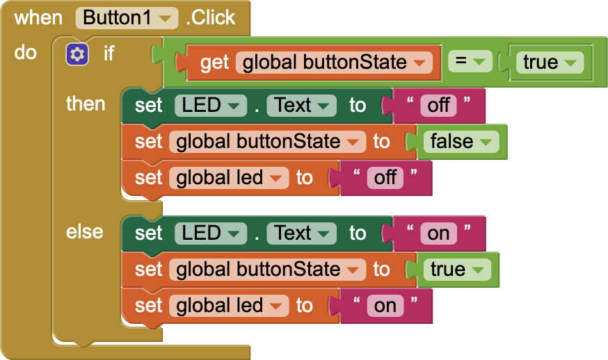
And the state is determined by the global varaible coolen bottonState. And similarly we have angle and led to store the data for the Slider and button.
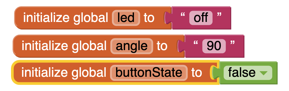
The slider will control the angle from 0 to 180.
Problems
When I was working with the app inventor on chrome and I was using the Mit App Inventor companion app. But most of the times my phone will not be able to connect with the project.
Mostly the platform displays Connection error.
Solution: To solve the issue, I browsed around to find an answer and in one of the forum it said that chrome has been giving this issue. Therefore I downloaded firfox and now the issue is gone.
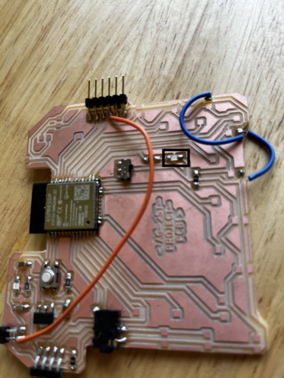
Circuit Board.
The board is same from the networking week board, which is the first iteration of my final board. The new thing added to this board is the 3 pin 2.5 mm audio jack connector.
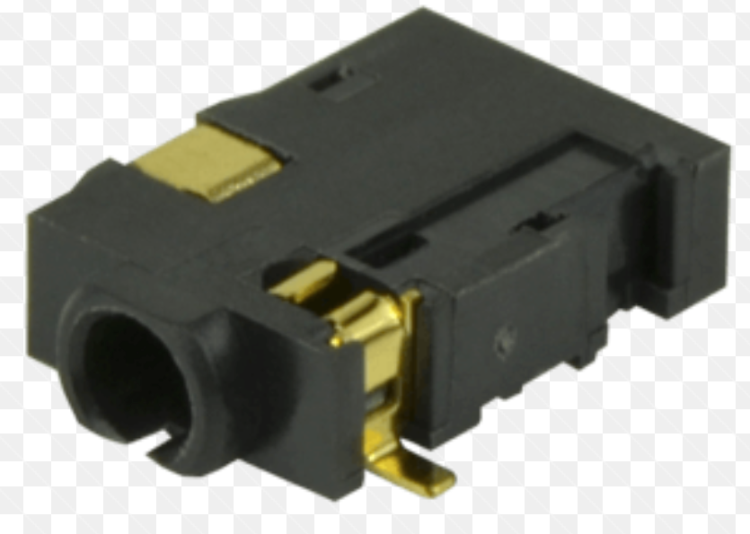
The image below shows the connector soldered to the board. The signal pin is connected to th GPIO 32 pin of the ESP32.
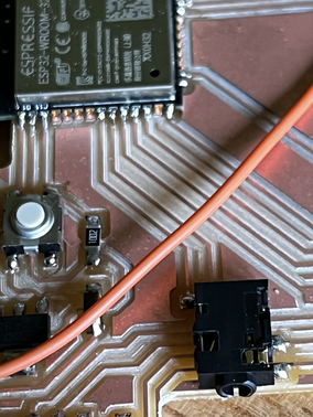
The 2.5 mm audio jack is soldered with the old jumper wires with male header pin on the other side. So that the servo pin can be connected easily with the audio jack.
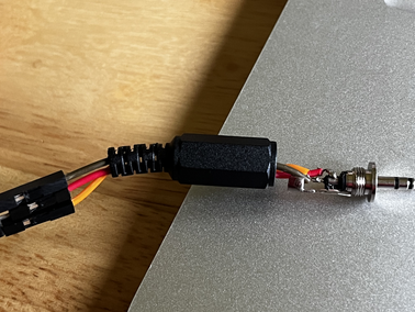
And hence the servo can be easily connected or disconnected from the board.
Arduino Program.
I browsered the internet explore more on connecting the ESP32 and the app from the Mit app Inventor. After going through various sites and trying out different codes I found a code which will generate a static IP on the wifi network.
The reference was taken from here.
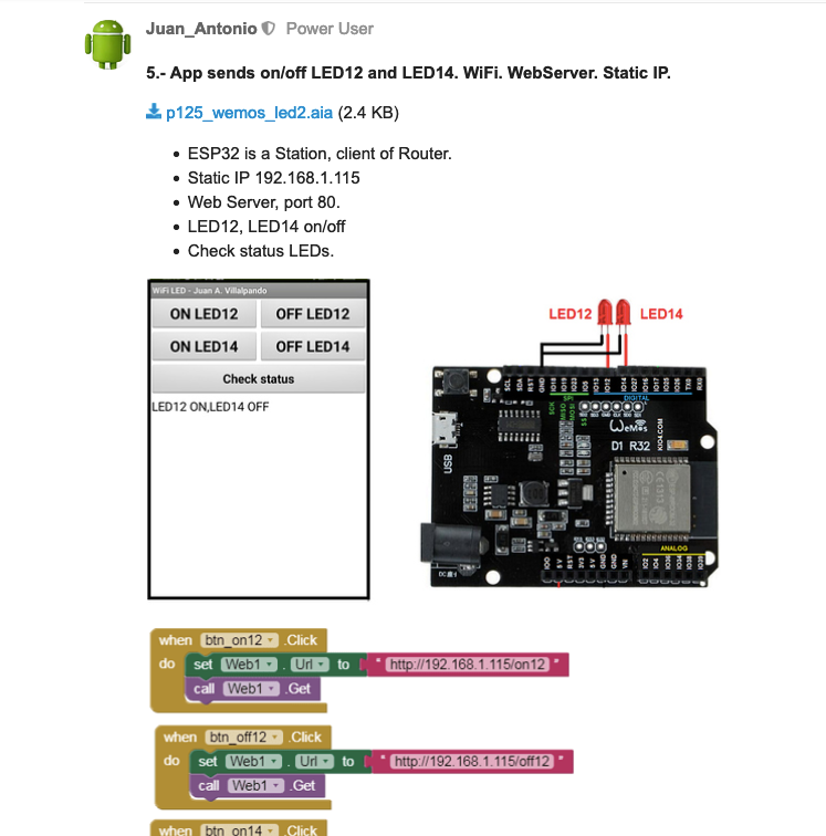
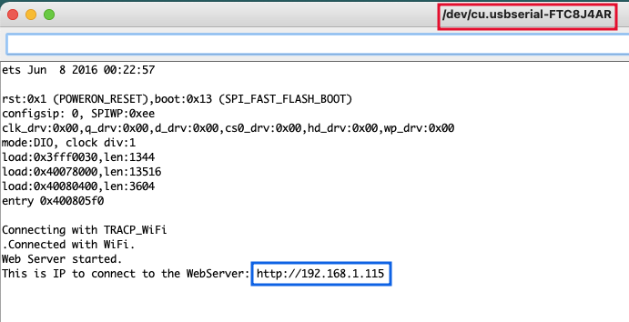
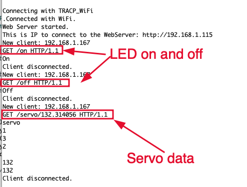
From the app, when ever an action is performed the changes are sent in the url of the HTTP GET request. - A static IP address will be generated at 192.168.1.115 as shown below. FTDI is used to program and communicate with the board.
The url are hardcoded on the block code of the app.
ESP32 and Servo.
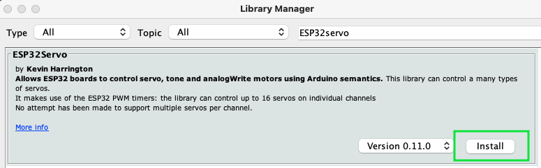
To control the servo motor using the ESP32, first we have to install the ESP32Servo Library from the Library Manager.
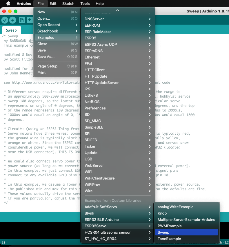
After installing the library, go to the examples and find the sweep file of ESP32Servo Library to check the servo.
And Finally the final code for the week is made with reference from the here and the sweep code.
The slider value was added to the url and to get the integer value of the angle sent from the app. The data is collected as a String as shown below.
Hence to get thr required data, the string is converted to an array of characters. Then based on the index of the data required from the array, the values are assigned to another array called angle under the function int getAngle(String url) and using the atoi() function the value is converted to integer.
The function used to convert the string to integer for the position of the servo.
int getAngle(String url){
   char servo[15];
   char angle[4];
   int sub = 11;
   url.toCharArray(servo, 15);
   for(int i=11; i<15; i++) {
    sub = i - 11;
    angle[sub] = servo[i];
    //Serial.println(servo[i]);
   }
   //angle[4]= '\0';
   int angleValue = atoi(angle);
   //Serial.println(angleValue);
   return angleValue;
}
Testing.
Using the AI Companion feature in the MIT App Inventor the project is easilly linked to my computer.
Now the app is connected on the phone.
add UI image
The video below shows the full process for using the application and interfaing with the components over a wifi network.
Problem.
Initially my esp would generate IP address for the device but the app was not able communicate with esp. Therefore to solve the problem I predefined the ip address for the esp and connect the app to thet same address. Which provided higher rate of connection between the devices on a same network.