5. Electronics production
This week was about electronic production, where our goal was to mill a predesigned in-circuit programmer. This programmer will used to program the controllor board which will be desiged soon in the coming weeks.
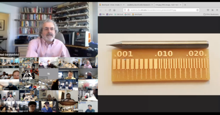
And for the group assignment we had to characterize the design rules for PCB Production process.
I had experiences working with electronics but never had an experience with designing and PCB and milling it. It was mostly working wit perfboard.
In-circuit programmer.
Image result for in circuit programmer In-system programming (ISP), or also called in-circuit serial programming (ICSP), is the ability of some programmable logic devices, microcontrollers, and other embedded devices to be programmed while installed in a complete system, rather than requiring the chip to be programmed prior to installing it into the system. Wikipedia
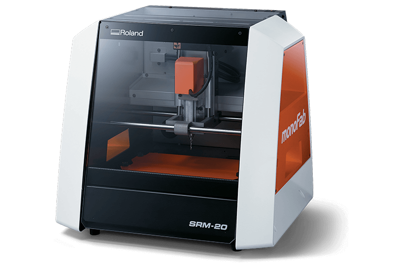
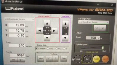
The machine used to mill the ISP is the SRM-20 Roland. The image below shows the SRM-20 Machine.
Fabrication.
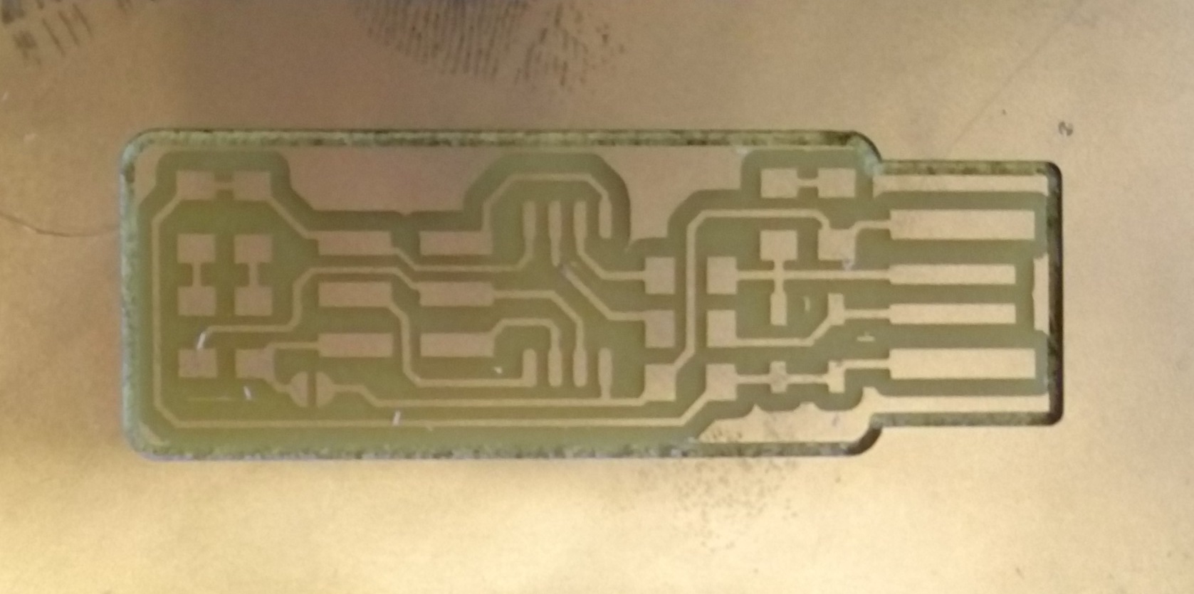
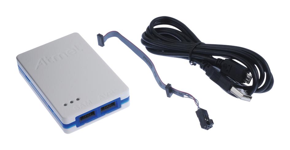
As per the advice from the instructor and availability of the components in the lab inventory. I decided to fabricate the Brian ISP. The image below is the trace and cut file of the selected ISP.
- fts_mini_traces.
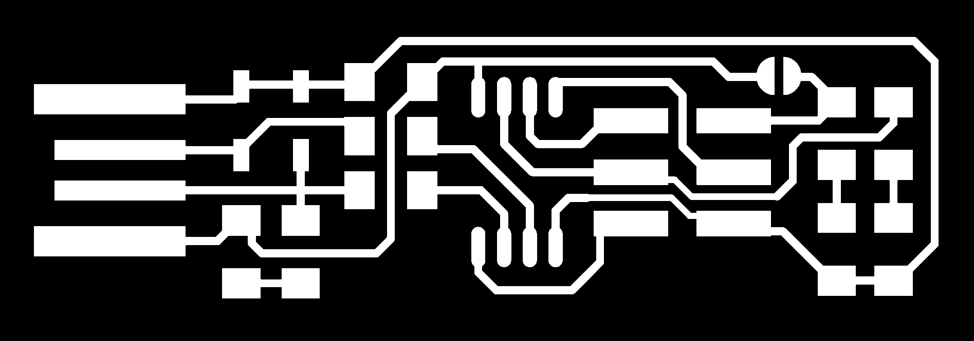
- fts_mini_cut.

Generating RML file.
We will generate the rml file from the online MIT Mods. When we open the given link, right click and select: -> program -> open server program -> select PCB png under SRM-20.
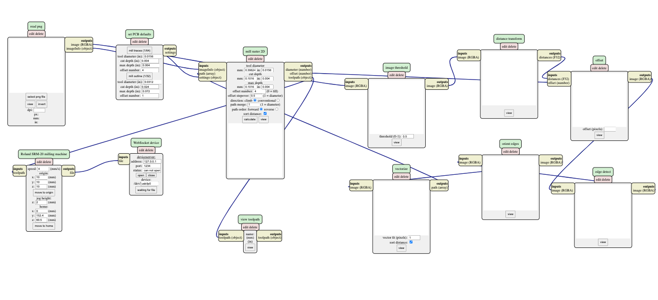
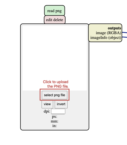
- First we will select the png file to generate the trace or cut rml file.
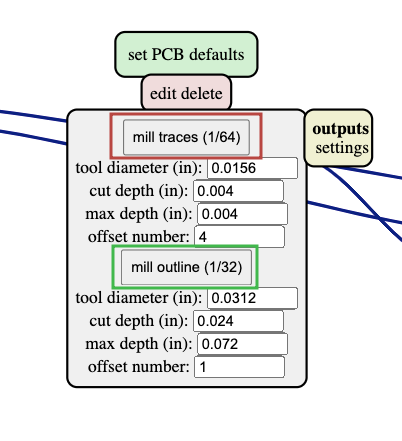
- Then select the type of endmill, for the tracess we can select 1/64 and for the edge-cut we can select 1/32.
After that delect the websocket device tap and to download the rml file. - Right click -> modules -> open server module -> the select sub-list save under file section. And connect the output of Roland SRM-20 milling machine tap to the input of the save tap as shown below.
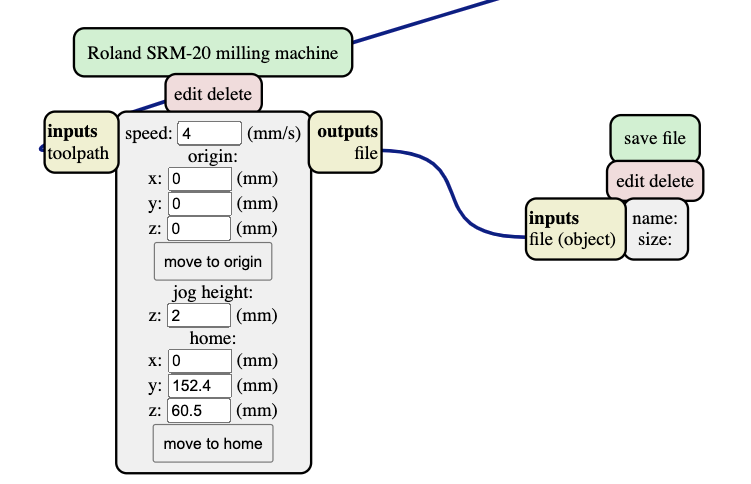
note: keep the orgin coordinates to zero (i.e x = y = z = 0).
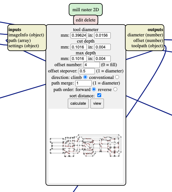
Finally on the mill rastor 2D tap, click calculate to generate the rml file.
Milling the ISP.
After generating the RML files, we will use the V-panel software, which is a machine software to control the SRM-20 machine.
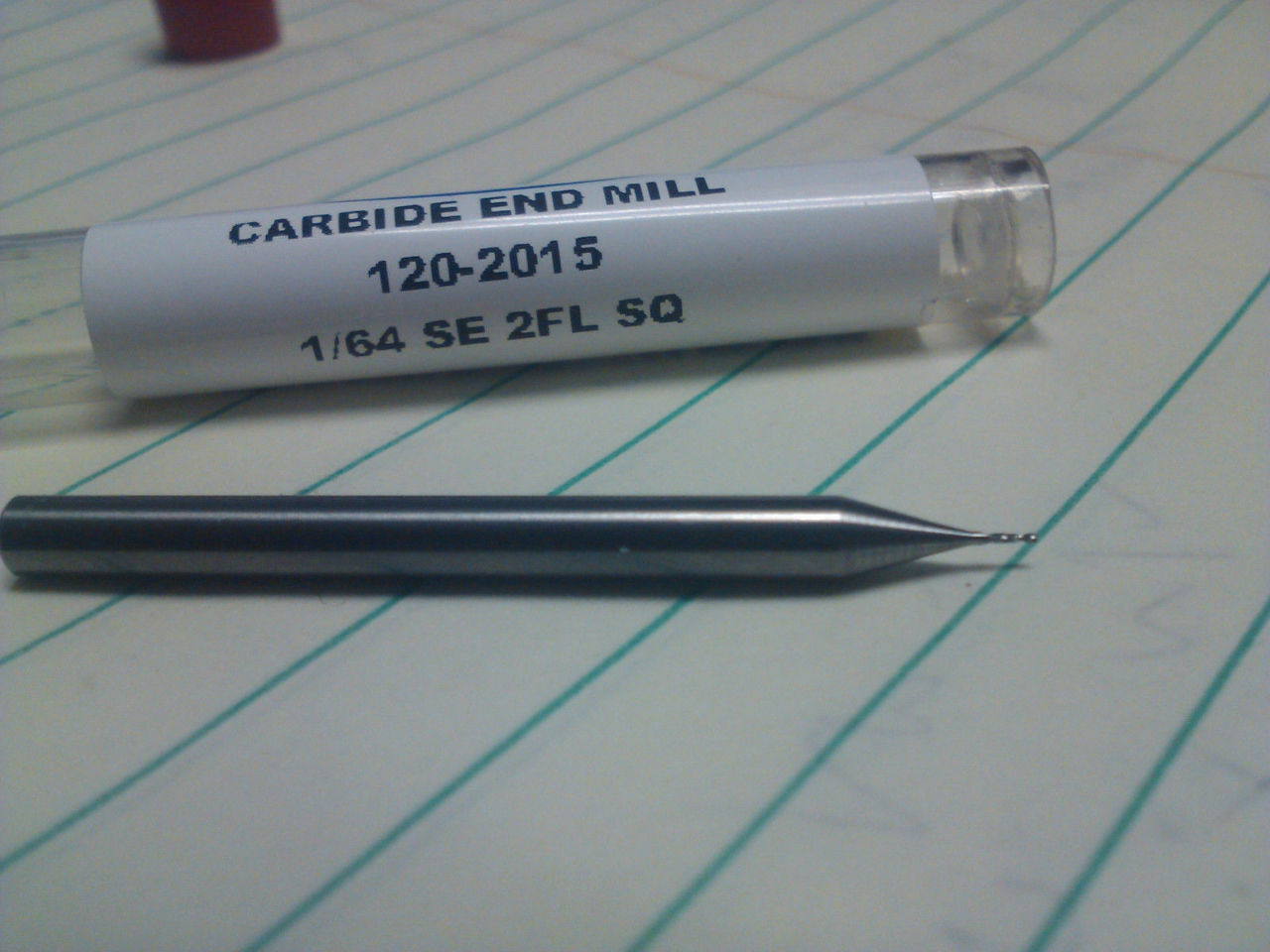
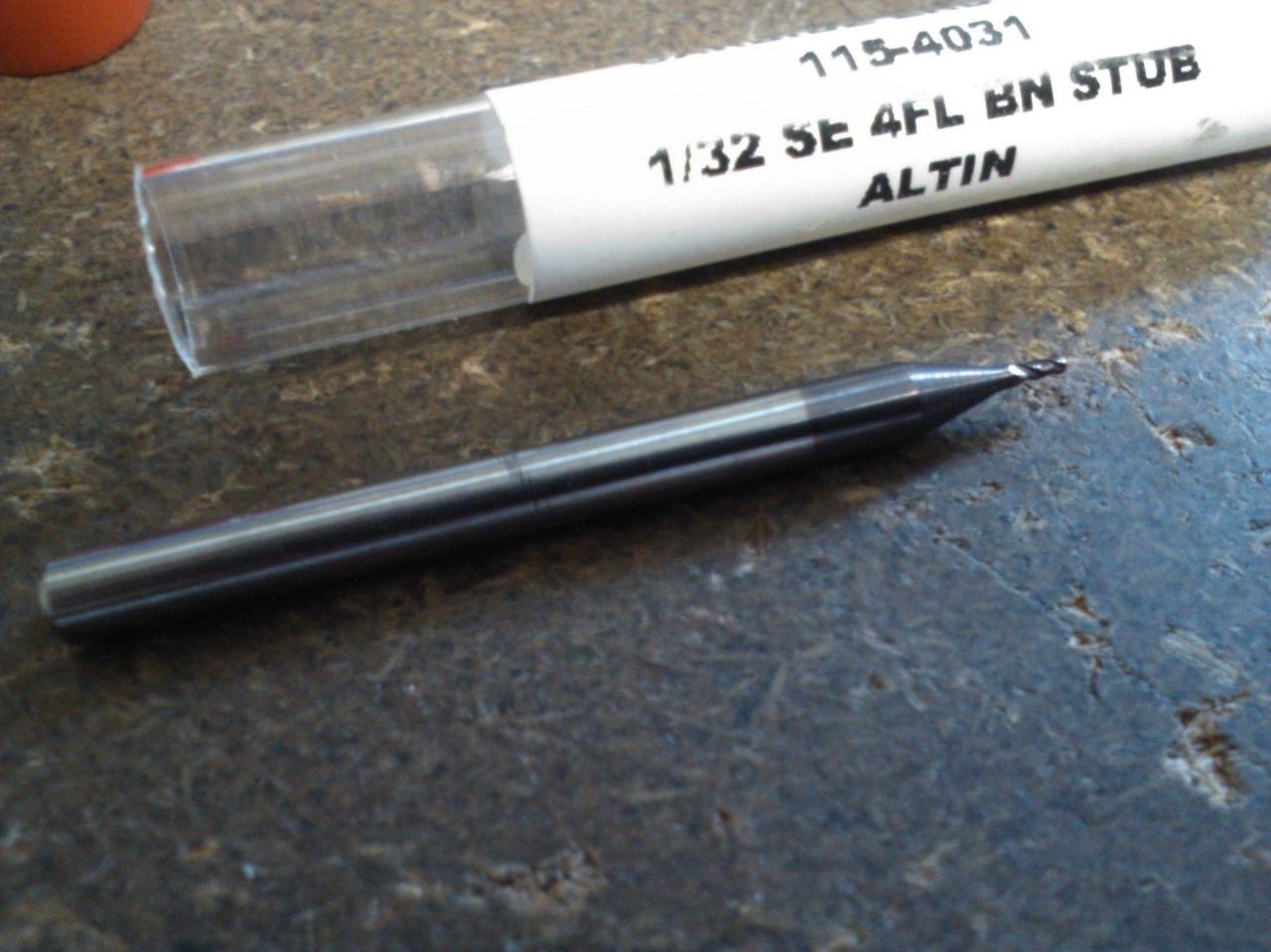
Note: To engrave the traces, we will use the 1/64 endmill and to cut the edges we used the 1/32 endmill.
- 1/64 Endmill.
- 1/32 Endmill.
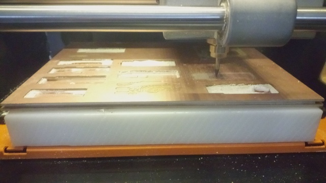
First we wil set an origin at point over the copper plate. After setting the origin we used to zeroing method to make the endmill touch the copper plate, so that the engraving process is precise.
-
Then add the trace RML file to engrave the traces on the PCB.
-
Then add the edge cut RML file to cut the edges of the PCB.
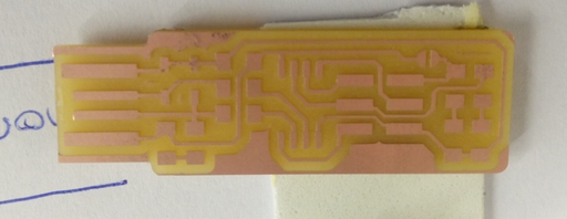
Then using the spatula, the milled PCB is taken out for the next step.
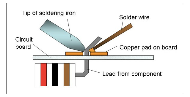
Soldering The Components.
What is soldering? - Soldering is a process in which two or more metal items are joined together by melting and then flowing a filler metal into the joint—the filler metal having a relatively low melting point. Science Buddies.
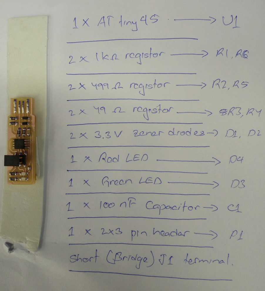
Before soldering all the components are collected from the inventory and made ready for soldering.
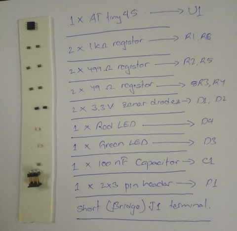
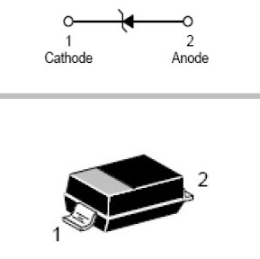
Some of the components have cathode and anode terminals, therefore we should take note of the orientation of the components while soldering. Such as:
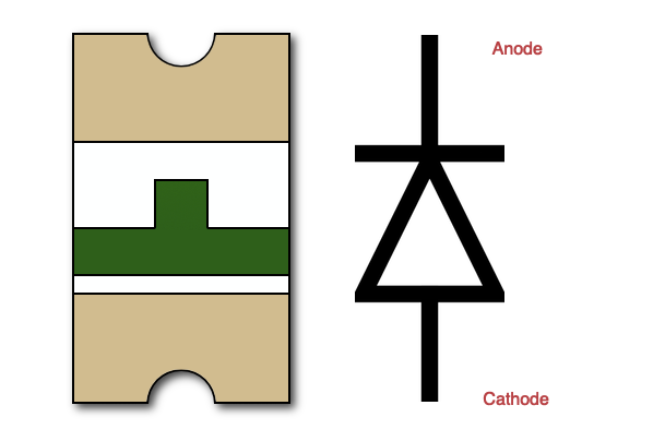
- For Zener diode, the line on the diode represents the cathode terminal.
- For LED, the side where there is a green line indicates the cathode side of the LED.
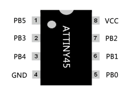
- And on the ATtiny45, the pin near a dot is the pin number 1.
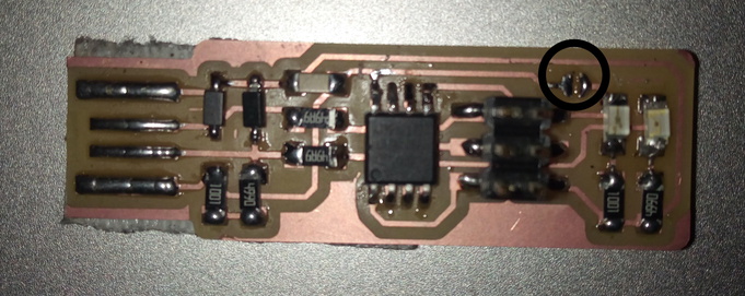
All the components were soldered. I started by soldering the low level components first. The image of the assembled ISP is shown below.
Programming the ISP.
The next step is to upload the firmware on the ISP using the Atmelice-ISP. To upload, I am using the Ubuntu OS from the lab PC.
- First run the command show below to start on the terminal of Ubuntu.
sudo apt install avrdude gcc-avr avr-libc make
- Download the Firmware. Unzip it and make the necessary changes such as on the makefile.c file change the ISP.
PROGRAMMER ?= atmelice_isp
- And save it.
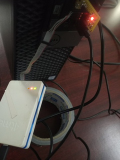
Now connecting the atmel ice programmer to my ISP and connecting the ISP and programmer to the computer to upload the firmware.
- The Red led of the ISP is the power led and green light on the atmel ice indicate thet it ISP has been recognize by the atmel Programmer.
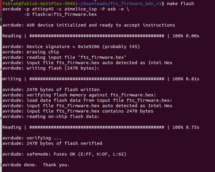
Now running the following command to check and successfully upload the firmware on the ISP.
make flash
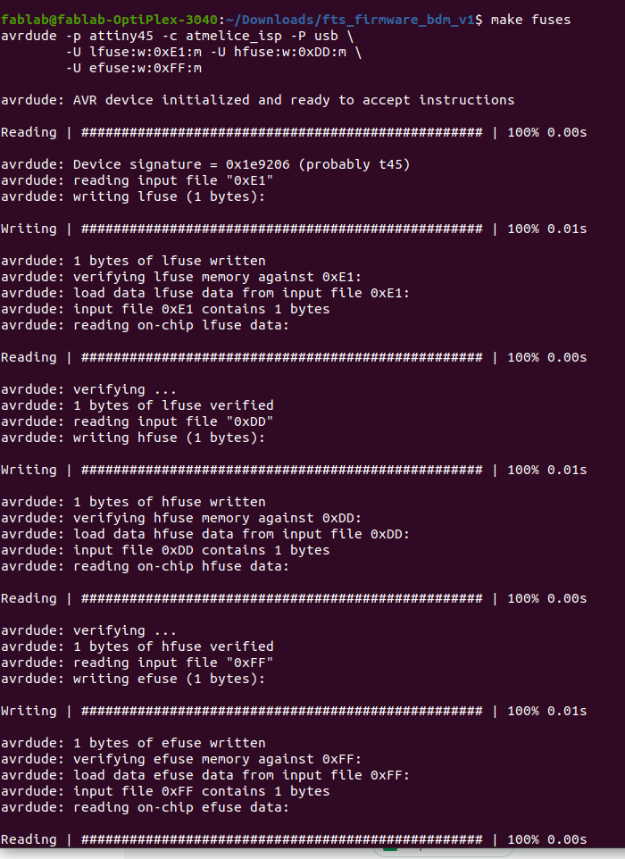
make fuses
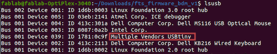
lsusb
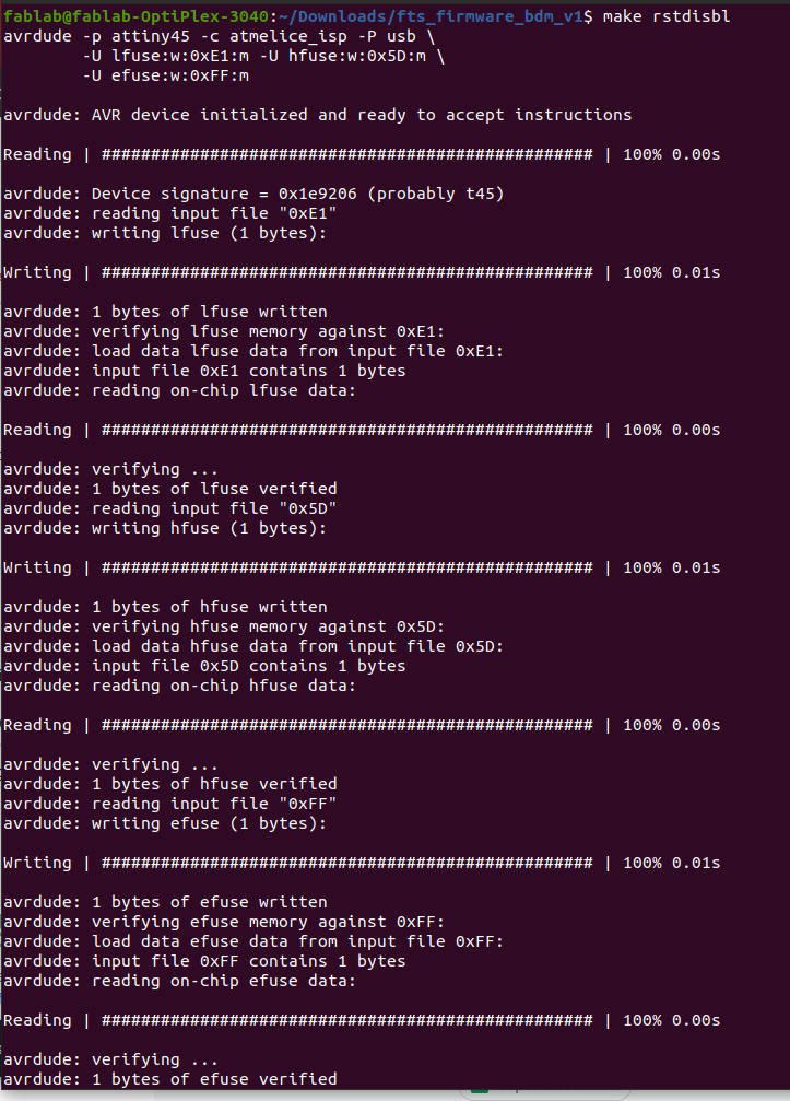
make rstdisbl
- Run make flash.
- Run make fuses.
- Run lsusb to confirm the upload of the usb.
- Finally run make rstdisbl so that avrdude will never be able to talk to this chip again through the ISP header.
Now the final task is to disconnect the connection between Vcc and Vprog, by desoldering the J1 terminal.
Group Assignment.
The group assignment can be viewed by clicking Here
Git Push Problem.
For this assignment, I had lots of images and I think the maybe due to the size of the commit. I was unable to push the update for my assignment. The error I got while pushing the file was:
remote: fatal: pack exceeds maximum allowed size
Therefore after surfing over the internet. I unstage my previous commits and started to push a file at a time. The command used to unstage the previous commit is:
git reset origin/master
And Finally problem was solved.