11. Output devices
This week was quite a hectic one, Along with Sibu and Fran we came to setup a lab at Punakha. Working with them gave us very good exposure. Coming back to the assignment, this week was about designing and fabricating of a controllor board cable of interfacing with an output device.
Task: Output Devices
- Group assignment:
Measure the power consumption of an output device Document your work to the group work page and reflect on your individual page what you learned
- Individual assignment:
Add an output device to a microcontroller board you’ve designed and program it to do something
Group Assignment.
The group assignment can be found here
Controller Board.
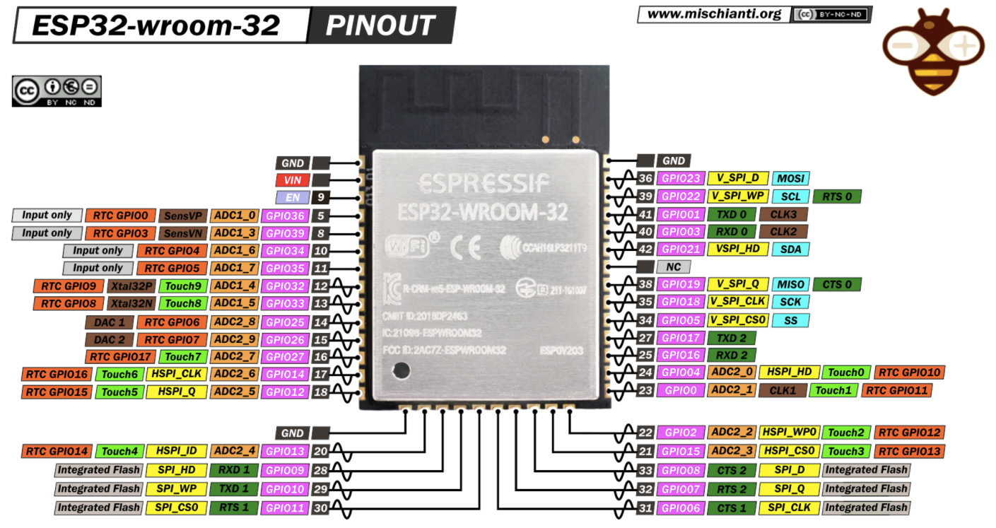
To complete this assignment first I decided to fabricate my final project board and work on with it. But since the Punakha Lab didnt had ESP32 WROOM.
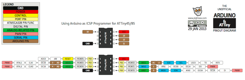
Therefore I decided to work with the design of AtTiny 45 controller to control the rotation of a micro servo motor.
And the output device is the micro servo motor, the image below shows the color code of the wires from the motor.
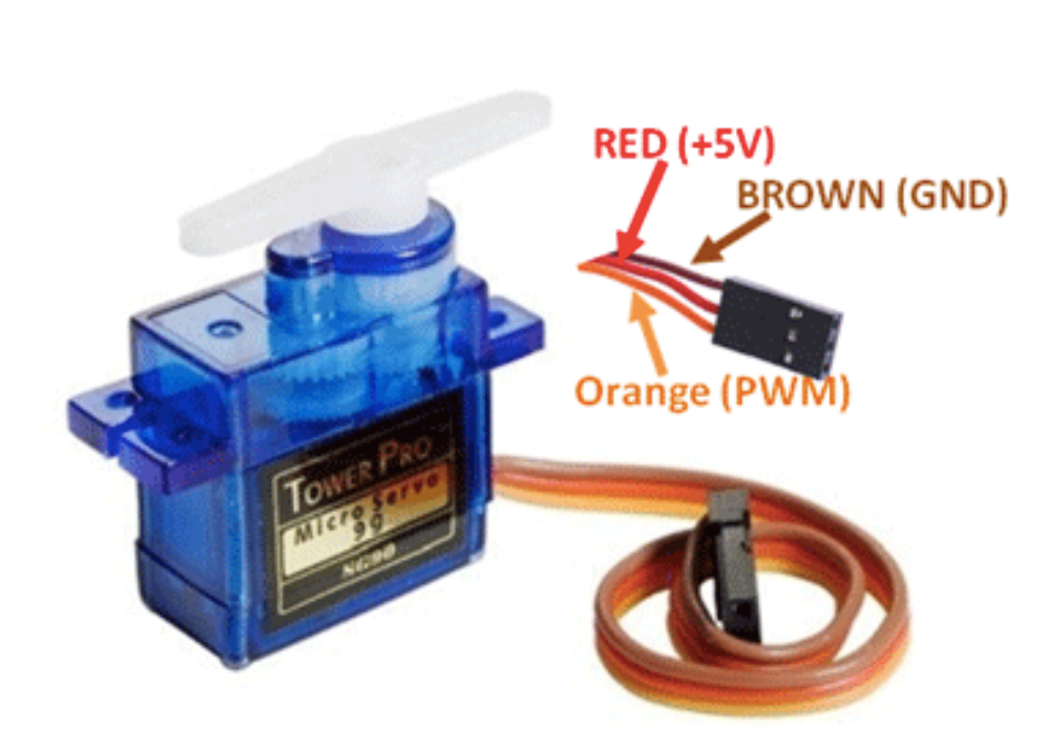
- A servo motor uses feedback in order to control the motor’s position, speed, or torque.
The position of the servo motor is determined by the length of the pulse given by the controllor. Hence the principle of Pulse width modulation is used to control the position of the shaft.
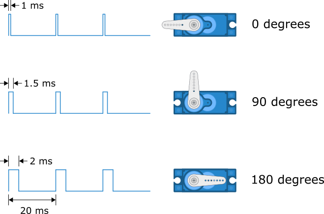
When you send the servo a signal with a pulse width of 1.5 milliseconds (ms), the servo will move to the neutral position (90 degrees). The min (0 degrees) and max (180 degrees) position typically correspond to a pulse width of 1 ms and 2 ms respectively.
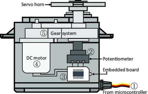
First, the desired angle trajectory is sent to a small built-in board from a microcontroller via a pulse width modulation duty signal. Second, the board receives the current angle position as proportional voltage through a potentiometer. Third, the board calculates the control input required to achieve the desired angle trajectory. Fourth, the DC motor is actuated by the torque exerted by the control voltage. Fifth, the generated torque is transmitted to the load shaft on which the potentiometer is placed. Finally, the above-mentioned steps are repeated with a fixed sample time.
Technical Details of servo motor:
Size: 23.1 mm x 12.2 mm x 29 mm
Working Voltage: 4.8-6v
Weight: 9 g
Speed at 4.8 V: 0.06 - 0.12 sec/60°
Compulsion Torque: 1.3 kg/cm
Torque: 0.06 - 0.12 sec/60°
Cable Lenght: 15 cm
Schematic Design.
For this design purpose I used the Kicad Software since it is open source and it would much realiable in the future as wheel.
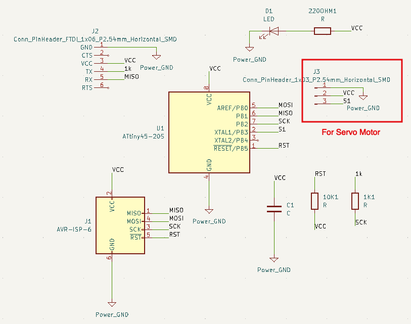
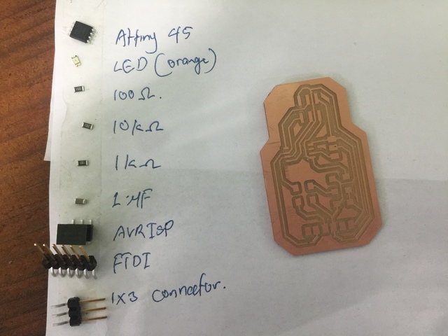
The Components used in this board are: - AtTiny 45. - FTDI connector. - Power LED and 220 ohm resistor. - AVR ISP. - 1k ohm and 10k ohm Resistor. - 1uF Capacitor. - 1x03 horizontal header pin.
The signal pin of the servo is connected to the PB2 of the AtTiny45 IC, which corrosponds to Pin no. 2 for Arduino.
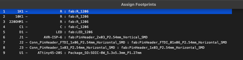
Then the next step is to assign the footprint to the each components as per the availablity of components in the Lab. The assigned footprints for each components are.
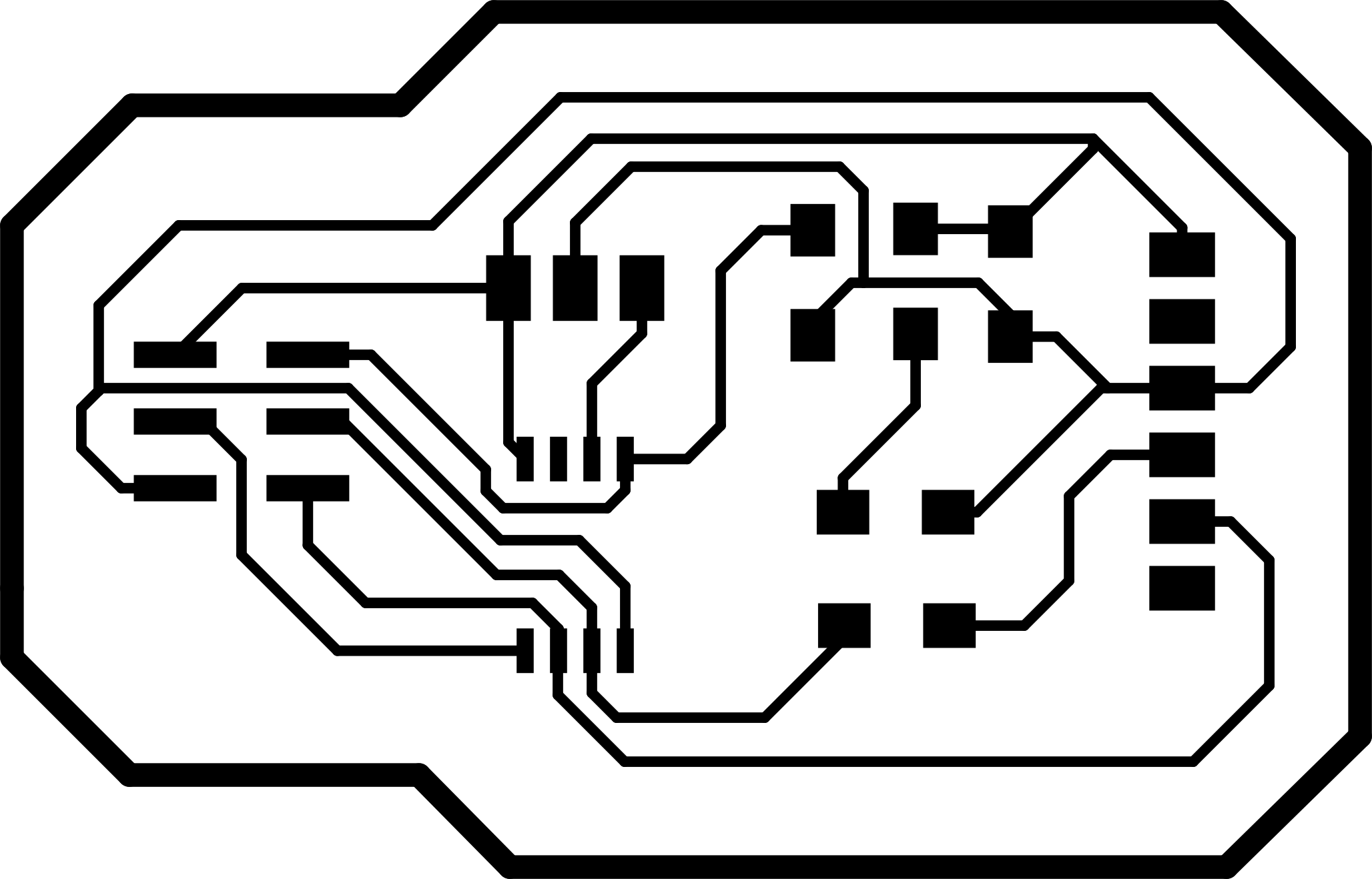
PCB Design.
After assigning the footprints and completing the Schematic works, now the next task is to design a PCB layout and make it ready to mill. The image below is my finaly layout of the PCB.
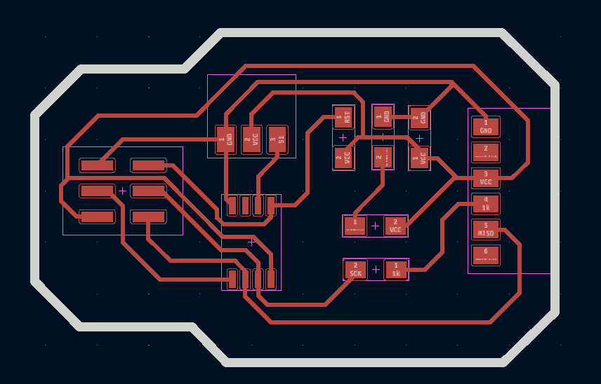
After working often with the routing and layout design. It has become easier to do the routing work.
Ater the designing work is done, now the the file is exported in SVG format.
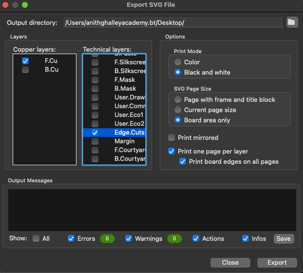
InkScape (Svg to Png).
To generate a RML file, we need the traces and edge cut files in PNG. Therefore we will be using the InkScape software to generate a png file from the svg format.
The image below shows the process to use inkscape to convert svg file to png.
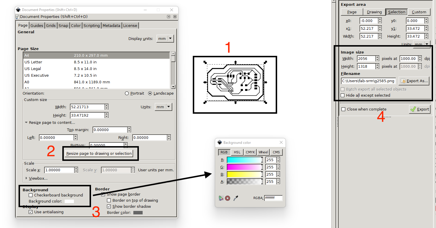
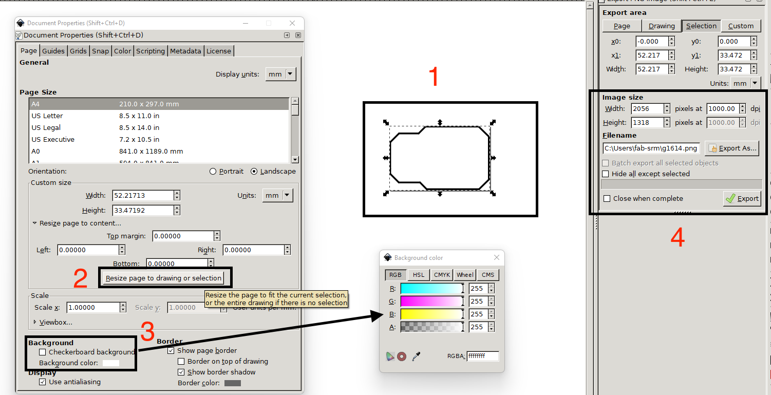
The process is in this way:
- Select the traces or edges from the imported svg file.
- Go to document properties and click on resize page to drawing or selection.
- Set the background file white.
- Export the image with pixel at 1000 dpi.
The png files are:
Edge Cut PNG

Front Traces
RML file.
And then using the mit mod. Similar to the previous way like from electronic production. Always take note of.
- Invert the image so that the traces are of white color.
- Select 1/64 for the traces and 1/32 for the edge cut.
- Set the origin to x = 0, y = 0, z = 0.
- And add the save module.
With this steps and the png files, we were able to generate the rml file.
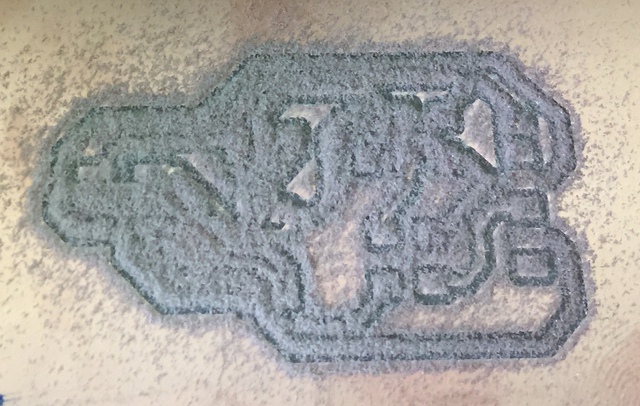
Milling the board.
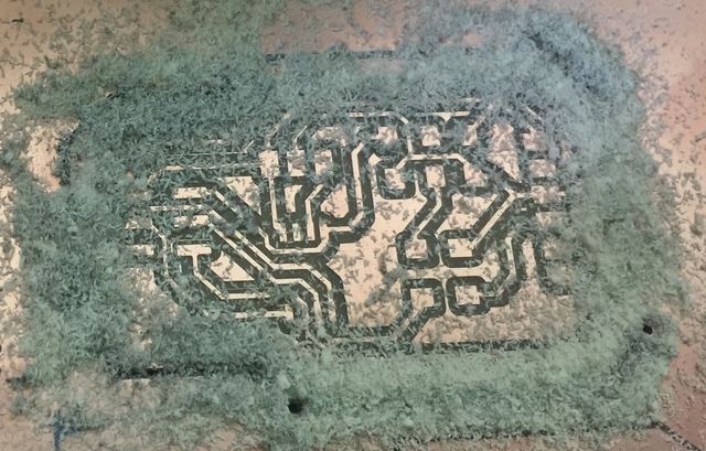
After generating the RML file we will use the 1/64 endmill to cutout the traces and 1/32 endmill to cutout the board outline.
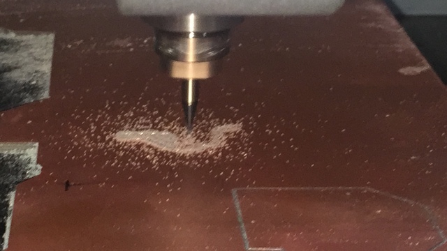
The trace cut of the output week board.
![]()
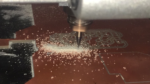
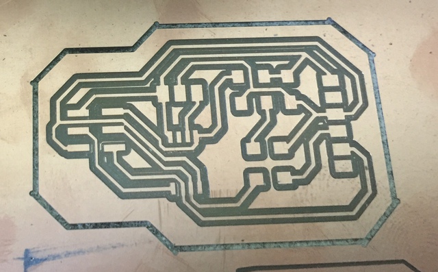
Now the next job is to cut the edges of the board using the 1/32 endmill.
Assemble of components.
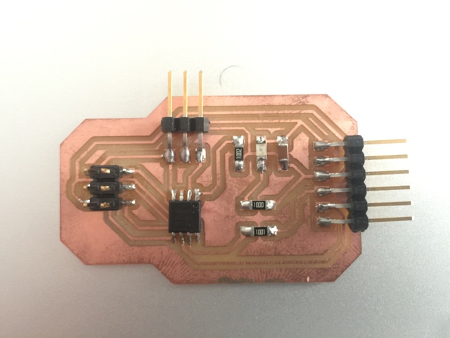
After fabricating the PCB, now the next step is to assemble all the components on the PCB board.
The Assembeld board is shown below.
Programming
Using SoftwareServo Library.
First I tried to run the arduino Library servo sweep code in the AtTiny45 but that didnt work.
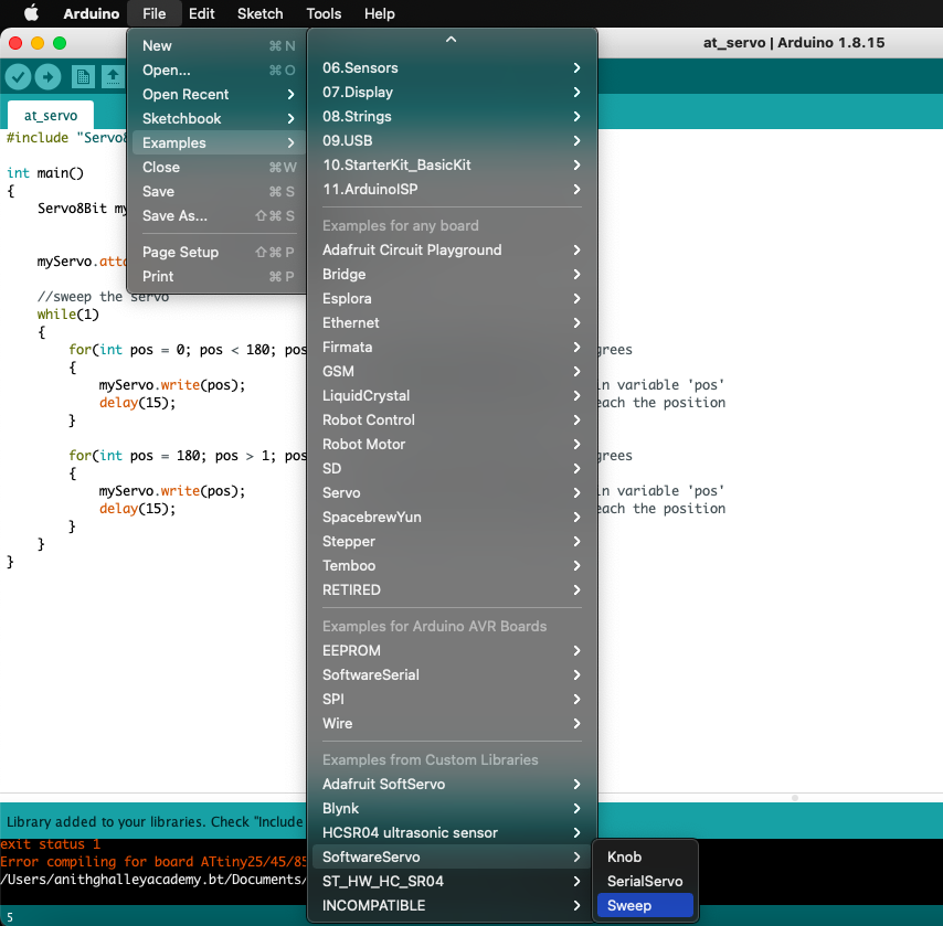
So after exploring and browsing over I came up with the Library SoftwareServo. Then the library was added to my Arduino IDE Libraries.
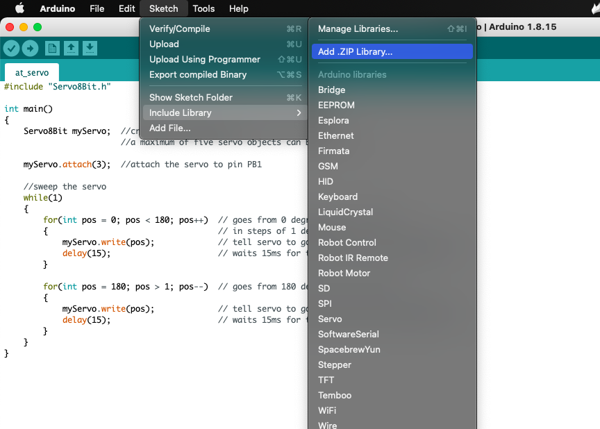
Then with the lbrary added and from the examples of of the SoftwareServo can be used to program my board. The example used was the sweep code form SoftwareServo Library.
This code is very much similar to the arduino sweep code but instead of servo.h, it includes oftwareServo.h.
#include <SoftwareServo.h>

SoftwareServo myservo;
The video below shows the output device servo motor controlled by the AtTiny45 controllor.
Using Adafruit SoftServo Library.
The Library will be added same way as shown for the SoftwareServo library.
Under this library only one example is available called Trinket knob.
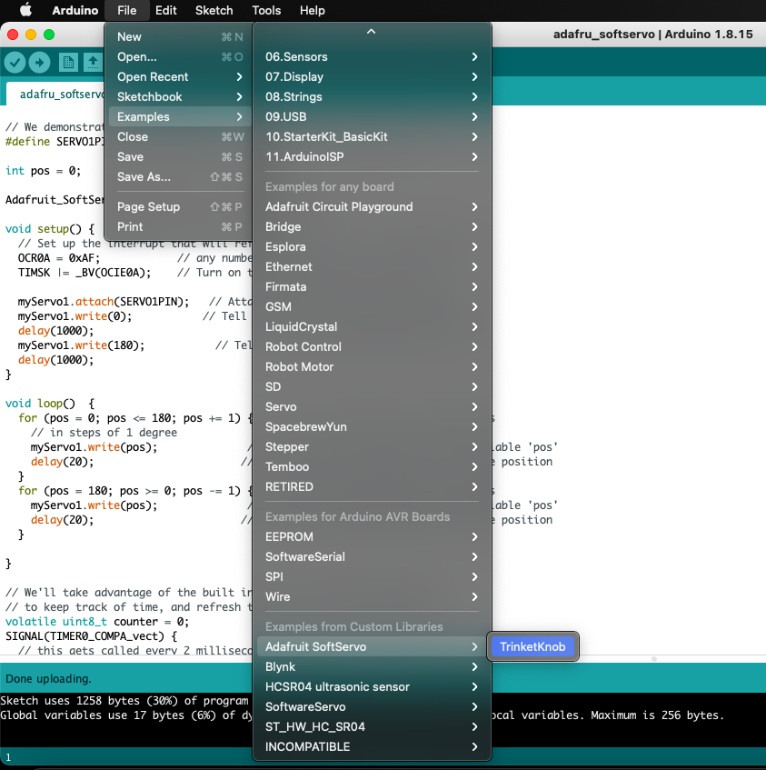
I took this example and manipulate the code to run only one servo without a knob. The sketch can be found under files at the end.
And the video below shows the code execution with the adafruit soft servo library.
Files.
- SoftwareServo Library
- Adafruit_SoftServo Library
- Manipulated Trinket Knob Code
- Edge Cut Png
- Front Traces
- Kicad File