Final Project
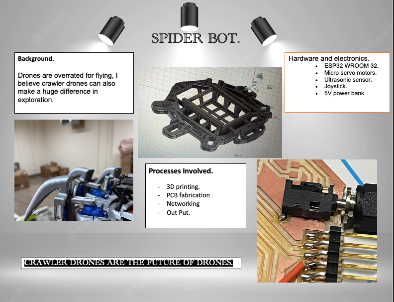
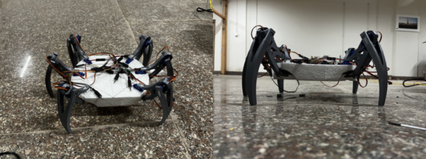
I have always been very amazed by the crawler drone then the glying drones. advancement in the flying drones have shown great deal of advantage in the field of exploration. Therefore For this fabacademy final project I want to design and develop a crawler bot where it will move around on its own trying to avoid obstacles infront of it and there can be human intervention to pass over an obstacles from a webserver hosted by the ESP32.
Project Sketch.
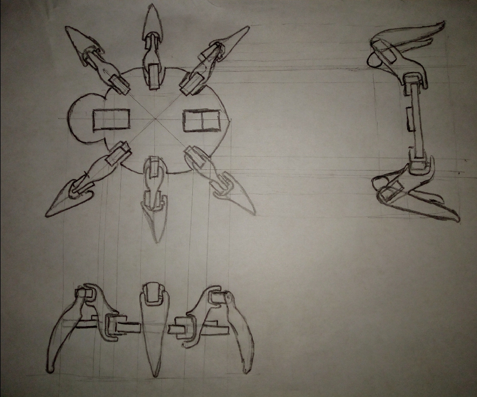
Modules Required: 1. Power supply 2. Microcontrollor 3. Servos (12 Nos) 4. Ultrasonic Sensor.
Research
Movement of the spider will mimic the movement of ants limbs Because spiders are usually eight-legged, so to reduce the number of servos being used the spider will have 3 pairs of legs, each legs will have two servos. The locumotion for this spider bot will be based on the locumotion of other three legged insects.

Locumotion of three-legged insects: While walking usually they either move one or two limbs at a time but When running, an insect moves three legs simultaneously. This is the tripod gait, so called because the insect always has three legs in contact with the ground: front and hind legs on one side of the body and middle leg on the opposite side.
Working concept
The spider would move forward when there is no obstacles in front of it and when ever there is an obstacles at a range less than 50 cm, The crawler will randomly find a direction with no obstacle inside the front range of the ultrasonic sensor. The crawler shoud also be able to connect to the given network so that at times human intervention can also be provided.
Why human interventation.
For a flying drons to reach its current stage advancement where it can fly on its own. But before that it was tried out with various human interventation menthod. Therefore I think that for the crawler drones to to advance, I want to keep the drones to a certain range of control from the user.
Modules Required: 1. Power Supply. 2. Micro-Controller 3. Ultrasonic Sensor 4. Servo Motors
3D design.
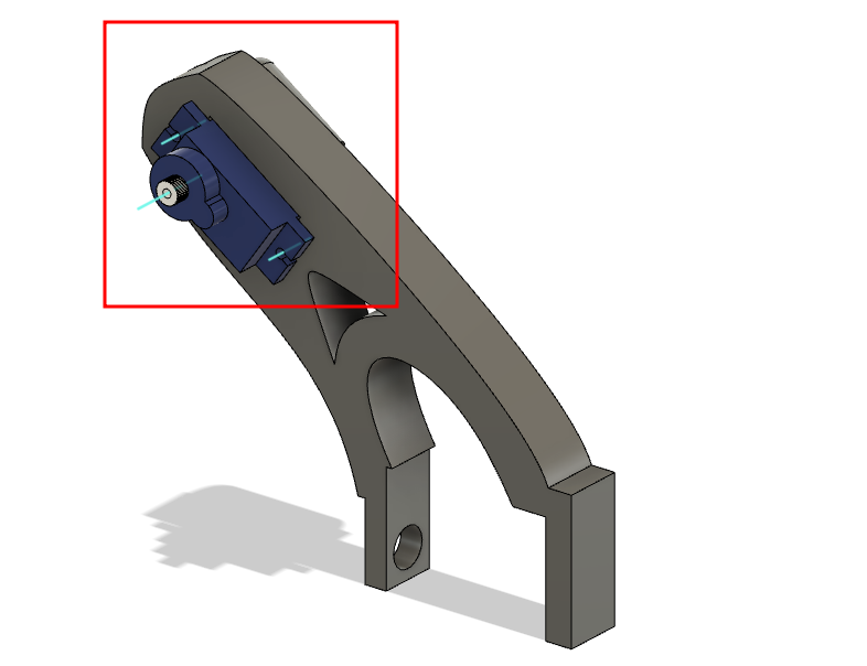
For now a limb for the spider-bot, various limbs has been designed and tested and were modified to improve the design the model below is the design with servo and joints.
Model
The model below was designed during the computer aided design week.
The model designed was studies with joints and the video below shows the motion study of the joints of the limb design.
- Motion Study Video:
- Components Explosion Video:
Prototype building.
I started with building the prototype because I felt that the motion of the crawler would be the core feature of my project and hence decide to make a protype.
Now with above design, I decided to first make a simple prototype to understand the movement of the crawler bot. The walking machanism I have planed is from the movement pattern of ants.
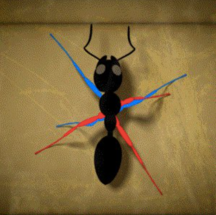
The ants movement on it limbs follows an alternating tripod pattern, where as shown above in the image the six limbs are devided into two tripod stand.
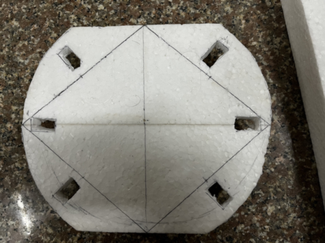
Therefore, for the body I used a thermocol and gave it a shape.
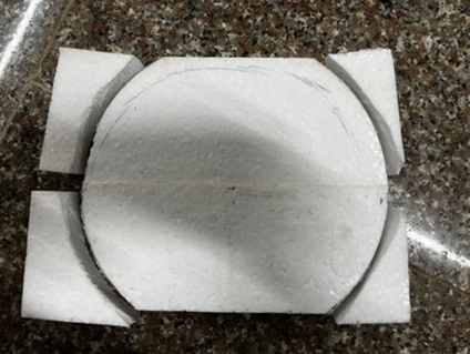
And holes of the servos.
Prototype Board.
From networking week onwards I started to work on my final project board and The board design is covered in the week assignment.
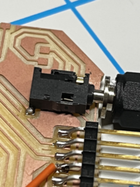
The image below is the PCB layout of my prototype board.
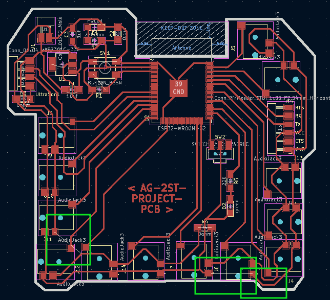
The green line indicates the missed connection and improvied the connection with wires to tet the rest of the connection.
And the image below presnent the new PCB layout after the testing using the prototype board. But I have to work on the shape of the board to adjust the circuit board on the spider.
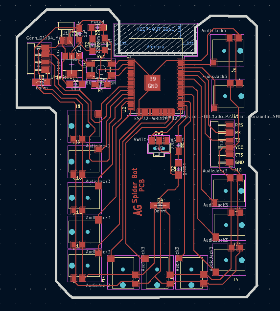
Using the prototype board, I was able to move all the servos connected to the board.
Connectors for servos.
To connect the servo with the PCB board I used the 2.5 mm 3 pin audio jack. The slots were soldered on the board.
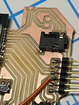
And the jack soldered with the cable of the servo.
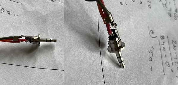
Hence making it easier connect and disconnect the motor.
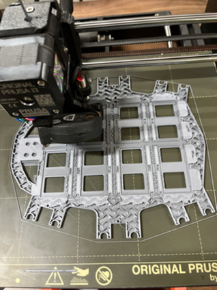
Assembling the bot.
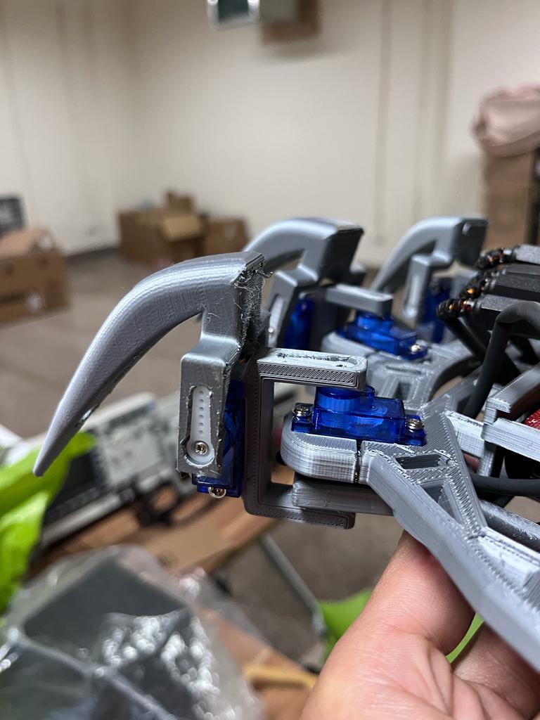
All the limbs were printed on Prusa printer. First when I printed my first design. That time I forgot to consider the servo cable for the second servo slot of the limb. In this design I should have made a connecting limb.
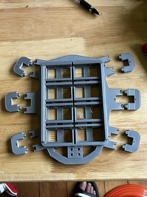
To solve this problem, I made a joint like a jigsaw puzzle as shown below.
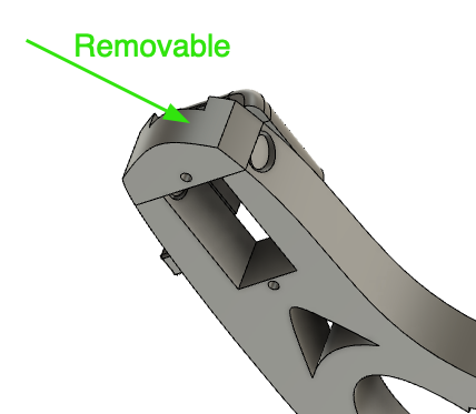
After solving this problem, all the limbs were printed and assembled
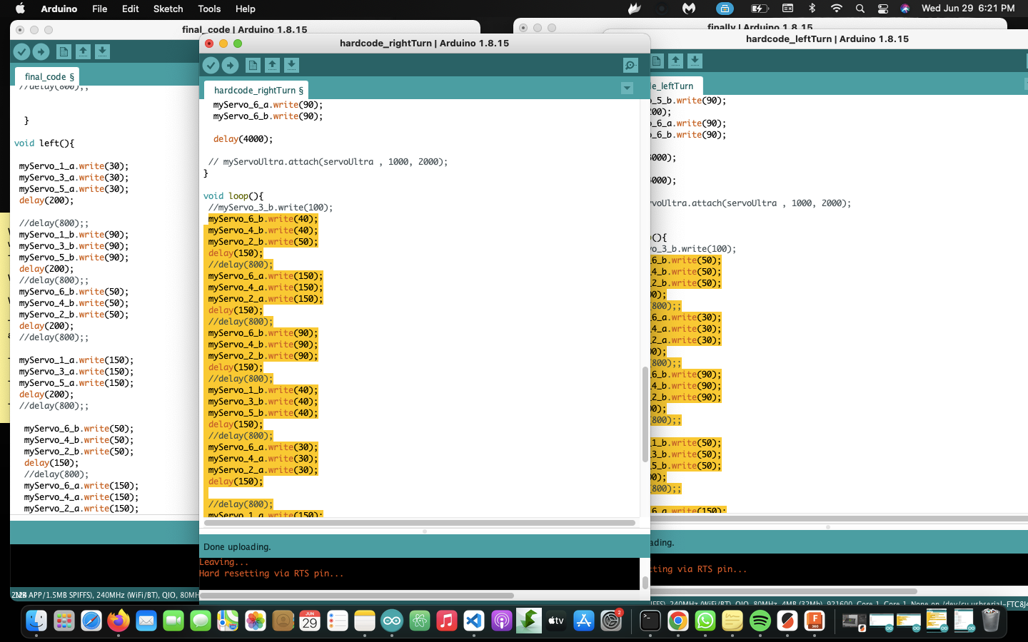
Programmming.
The software used is the Arduino IDE.
To control the servo, we cant used the arduinos default example. There fore to control the servo I used the ESPServo Library and add it to my library.
- Sketch -> Include Library -> add .Zip Library
And navigate to the downloaded library and selcet it.
So the Servo connectors are ready and the board is also ready, will be using the sweep example from the ESP32Servo example codes. The code used is.
Servo myservo;  // create servo object to control a servo

int pos = 0;    // variable to store the servo position


int servoPin = 32;


void setup() {
    // Allow allocation of all timers
    ESP32PWM::allocateTimer(0);
    ESP32PWM::allocateTimer(1);
    ESP32PWM::allocateTimer(2);
    ESP32PWM::allocateTimer(3);
    myservo.setPeriodHertz(50);    // standard 50 hz servo
    myservo.attach(servoPin, 1000, 2000); // attaches the servo
}

void loop() {

    for (pos = 0; pos <= 180; pos += 1) { // goes from 0 degrees to 180 degrees
        // in steps of 1 degree
        myservo.write(pos);    // tell servo to go to position in variable 'pos'
        delay(15);             // waits 15ms for the servo to reach the position
    }
    for (pos = 180; pos >= 0; pos -= 1) { // goes from 180 degrees to 0 degrees
        myservo.write(pos);    // tell servo to go to position in variable 'pos'
        delay(15);             // waits 15ms for the servo to reach the position
    }
}
Then code is uploaded and there were some problem due to not doing a good soldering but using the multimeter I was able to fix the problem and the Servo is rotating.
After testing the code then it was kept as references and developed a code to control 12 servo motors.
In the code we must keep in mind to write these three line for each servo. Which is: - Servo object:
Servo myservo;
- Servo Pin:
int servoPin = 17;
- Attach each servo it its asiiigned pin with the default min/max. I used 1000us and 2000us respectively:
myservo.attach(servoPin, 1000, 2000);
Movement pattern
The name I gave to servos are based on the limbs of the bot as shown belo
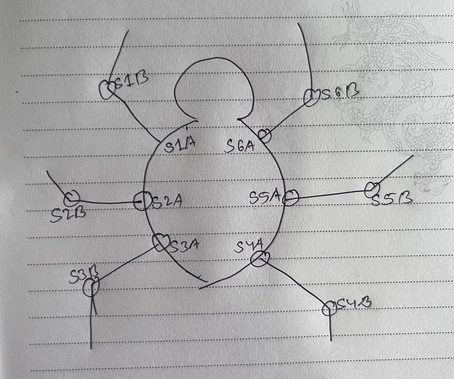
So the name of the limbs are also numbered like the numbering sequecne in the above image.
The movement pattern of the crawler will be like mention above about the alternating Tripod from the movement of the ants.
So there will be two tripod from the limbs of the ant.
Based on the number:
- 1, 3 and 5 will make one tripod and
- 2, 6 and 4 will form another Tripod.
There for Alternatively shifting the tripod can provide the machenism to walk and turn.
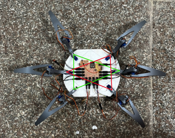
The red and green triangles shows the tripod formation.
Applying the concepts in the program, I was able to given motion to my crawler as shown.
Bot in Motion
The videos below are some of the results of testing motion of my crawler bot. Basically I am trying to check for different stable position and movemnets of the Limbs.
Left Turn
Right Turn
Forward Move
New crawler body.
Lesson learned from working on the motion I went on to design a body for the crawler and was printed. The same concept of jigsaw puzzle was apply to inserte the servo on the body.
The boady of the crawler is redesigned keeping the motions of the limbs, their stability and battery casing.
All the limbs were disassembled from the prototype and assembled to the new body. And the vieo below presents the assembled body and motion.
Problem.
But due to the long limbs of the crawlers the servos were not able to hold up to a precise angle and collapes.
Therefor the limbs needs to have some changes so that while the crawler is standing, the angle precision is maintained. Otherwise from my second model the crawler would move for sometimes and then collapses.
the third design was the game changer. The limbs were strong and no unecessary movements dure to lose joints.
The new Limbs.
The new designe of the limb is designed based on the idea to keep the limb perpendicular to the ground surface to minimize the extra force on servos and aviod slipping of the limbs.
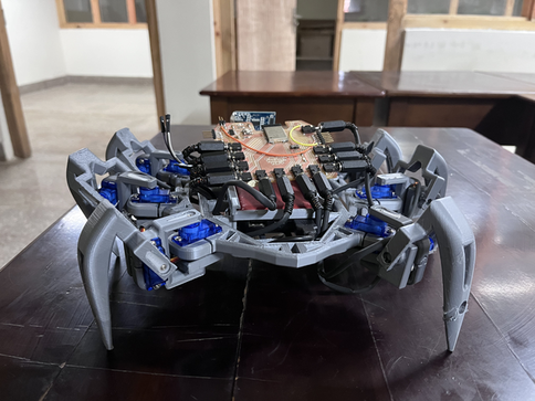
The video below is the Third Iteration of designing. This design can stand up with the power bank and all components on it.
Along with the lims the whole bodys design is changed to subsitute the batteries with a power bank.
The limb was printed and tested on the 2nd body but there were some issues and hence necessary was done and finally a good limb is being printed.
The design of the new body.
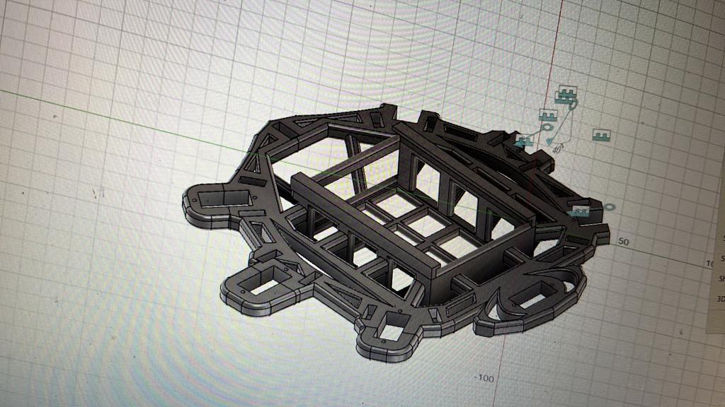
Next the body is also added to the printing process.
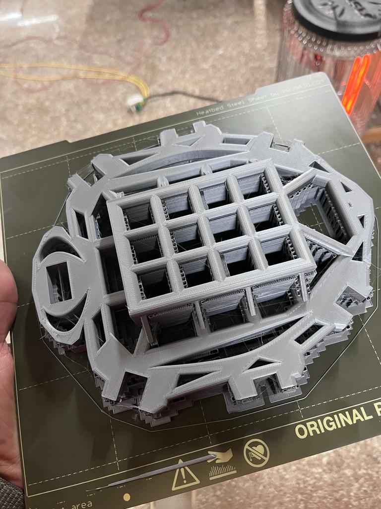
FInally my body is ready.
3D new Limbs view
Ultrasonic
The purpose of ultrasonic sesor is to detect if there is any obstacles in front. The code used to control the ultrasonic sensor is :
const int trigPin = 33;
const int echoPin = 26;

//define sound speed in cm/uS
#define SOUND_SPEED 0.034
#define CM_TO_INCH 0.393701


long duration;
float distanceCm;

void setup() {
  Serial.begin(115200);
  pinMode(trigPin, OUTPUT); // Sets the trigPin as an Output
  pinMode(echoPin, INPUT); // Sets the echoPin as an Input
}

void loop(){
  digitalWrite(trigPin, LOW);
  delayMicroseconds(2);
  // Sets the trigPin on HIGH state for 10 micro seconds
  digitalWrite(trigPin, HIGH);
  delayMicroseconds(10);
  digitalWrite(trigPin, LOW);

  // Reads the echoPin, returns the sound wave travel time in microseconds
  duration = pulseIn(echoPin, HIGH);

  // Calculate the distance
  distanceCm = duration * SOUND_SPEED/2;
  // Prints the distance in the Serial Monitor
  Serial.print("Distance (cm): ");
  Serial.println(distanceCm);

  delay(100);
}
Communication of boards.
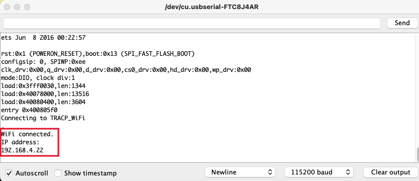
Communication between the computer and the ESP32 is over the wifi network and the ESP32 hosts a webserver to provide the user with interface as shown below.
This approache is share in the Networking Week. The interface for this work is as shown below.
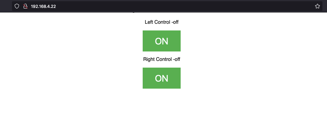
When ever the crawler detect an obstacle it will wait for user intervention from this interface when when left or right controlled is clicked it UI and the state changes.
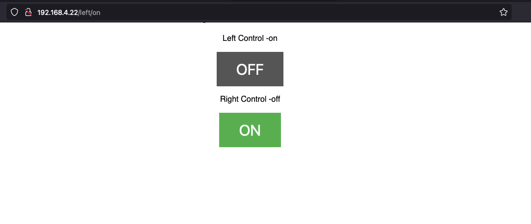
This UI can be accessed from the IP address provided by the esp32.
Final output.
In this video Below the demonstartion is that the spider is almost surrounded by some obstacles, When an obstacles is in the range of 50 cm in front it will go either left or right randomly. And only move forward when ther is no obstacle in the range of 50 cm.
But users can help the bot when it is not able to find a path with no obstacles. By change the state of Left and Right control on the interface.
The video will indicate the chamge of control state on the computer and different movement either by the spider or it is over written from the computer.