14. Networking and communications
This week is one of the interesting assignment till date. I have always been amazed with the wireless technology and communication is something which has come a long way and is one of the main reasons why technology has grown to this level.
Week Assignments
- Group assignment:
Send a message between two projects
- Individual assignment:
design, build, and connect wired or wireless node(s) with network or bus addresses
Group Assignment.
The group assignment can be found here
Communication Protocol.
The proper descriptions of digital message formats as well as rules are known communication protocols. The main function of these protocols is to exchange messages from one computer system to another. These are significant in telecommunications systems as they consistently send and receive messages. These protocols cover error detection & correction, signaling, and authentication.

-
Protocol: A set of rules and regulations is called a protocol.
-
Communication: Exchange of information from one system to another system with a medium is called communication.
-
Communication Protocol: A set of rules and regulations that allow two electronic devices to connect to exchange the data with one and another.
Reasons to have Network.
-
Location: With network, controls can taken by distant controllers. Basically communication between two different location.
-
Parallelism: In a computer sysyem, we can either process the tasks in one processor or divide the tasks among different processor.
-
Modularity: Rather then creating a big system, instead we can break the system into various modules to basically divide the work.
-
Interference: In a network the low noisy systems can be seperated from a noisy system. Hence minimizing the interference.
Wired and Wireless Network.
For every communication system medium is very important. Where the two communicating devices makes used of the medium to sent or receive datas. In the wired communication, two device communicate using the wired medium. Based on the distance, certain equipments such as switches, amplifier or repeaters are used to enhance the flow of the communication. The wired communication is much more realiable since there is minimum disturbance from the enviroment.
In wireless communication, usually the communication medium is the air. The performance of these protocol is determined by the type of communication protocol used. Since the type of protocol used directly affects the range of communication. Wifi and bluetooth are of short range protocol. Lora, GSM, FM and AM are of long range communication.
Asynchronous and Synchronous Tranismission.
Asynchronous transmission is also know as start or stop transmission. It sends data from the sender to the reciever usuing the flow control method. This type of communication isn’t generally conducted in person, nor is it planned for or scheduled.
Synchronous data transmission is a data transfer method in which a continuous stream of data signals is accompanied by timing signals. This type of communication can be virtual as well, either scheduled or a little more impromptu.
ESP32 Webserver.
In this assignment I tried to create an ESP32 webserver to host an interface to control one of the programmable LED in my circuit board.
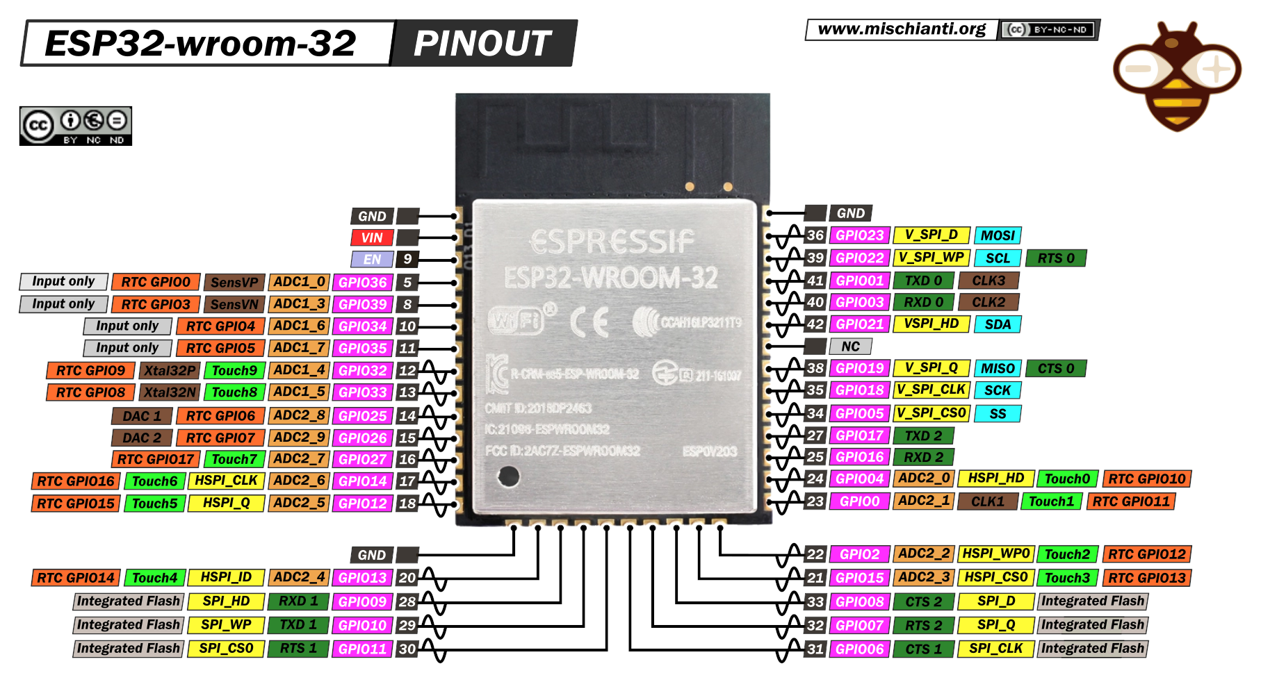
The image below shows the pinout of a ESP32 WROOM 32.
Board.
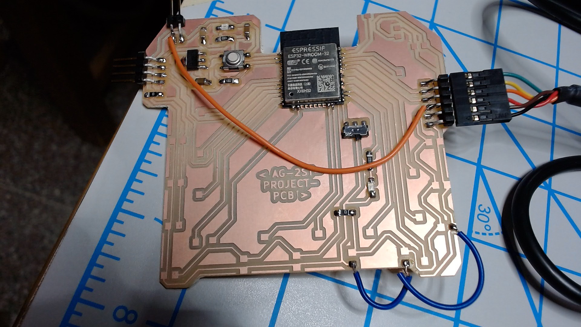
In this week assignment I decided to fabricate my first iteration of my final project board.
I referred the ESP 32 Hello World board. And made my own Schemetic as per the requirment of my project.
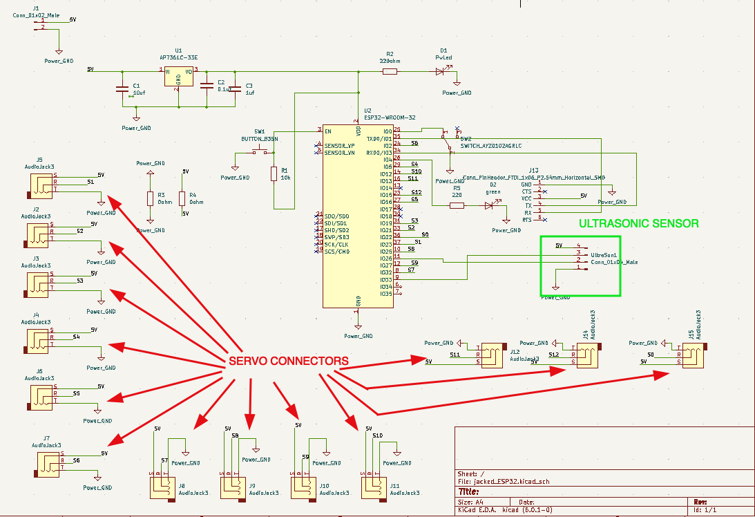
The components used in this schematic are:
- ESP32 WROOM 32.
- Red and Green LED.
- Resistors: one 10k ohm, two 0 ohm and Two Nos. of 100 ohm.
- Capacitors: 0.1 uF, 1 uF and 10 uF.
- 5V to 3.3V regulator.
- Switch: Slide and button Switch.
- Header Pins (Male).
- 3 Pins Audio Jack (For servos).
And the next step was to assign the footprints to the components. The assign footprints are shown below.
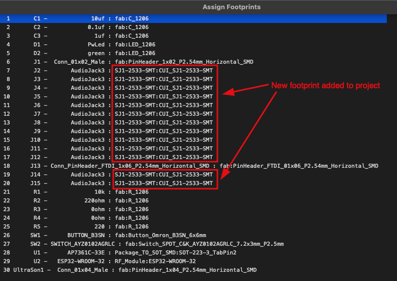
The footprint for the audio jack connector is downloaded from the snapeda website and the footprints is added to project specific.
PCB layout.
While making the layout of the board, the audio jack slots were not connected with any of the component like shown below.
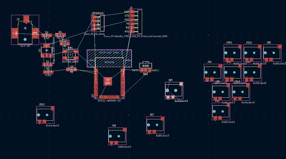
- Problem.
After browsing around I was not able to figure out the problem. The problem was in the schematic the pins were numbered as 1, 2 and 3. But in the foot print the pads were marked as TRS (Tip, Ring and Sleeve).
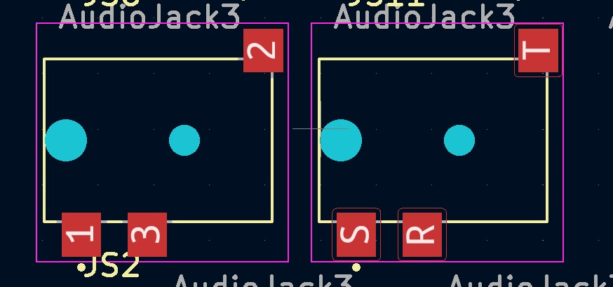
Therefore, from the main menu I edited the footprint and changed the Mark of the pads from 1, 2, 3 to T, R, S. Hence the problem was solved.
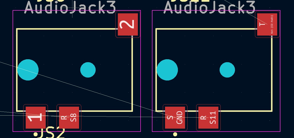
The final PCB layout is done but I forgot to ran the rule checker, Therefore resulting to having unconnected traces like shown below.
The third box was not unconnected track but the PCB outline was so close to the trace. later after milling the PCB, certain improvising tasks were performed.
PCB Milling.
Inkscape was used to convert the svg file png file and white background was added to the file. And the SRM 20 machine was used to mill the board.
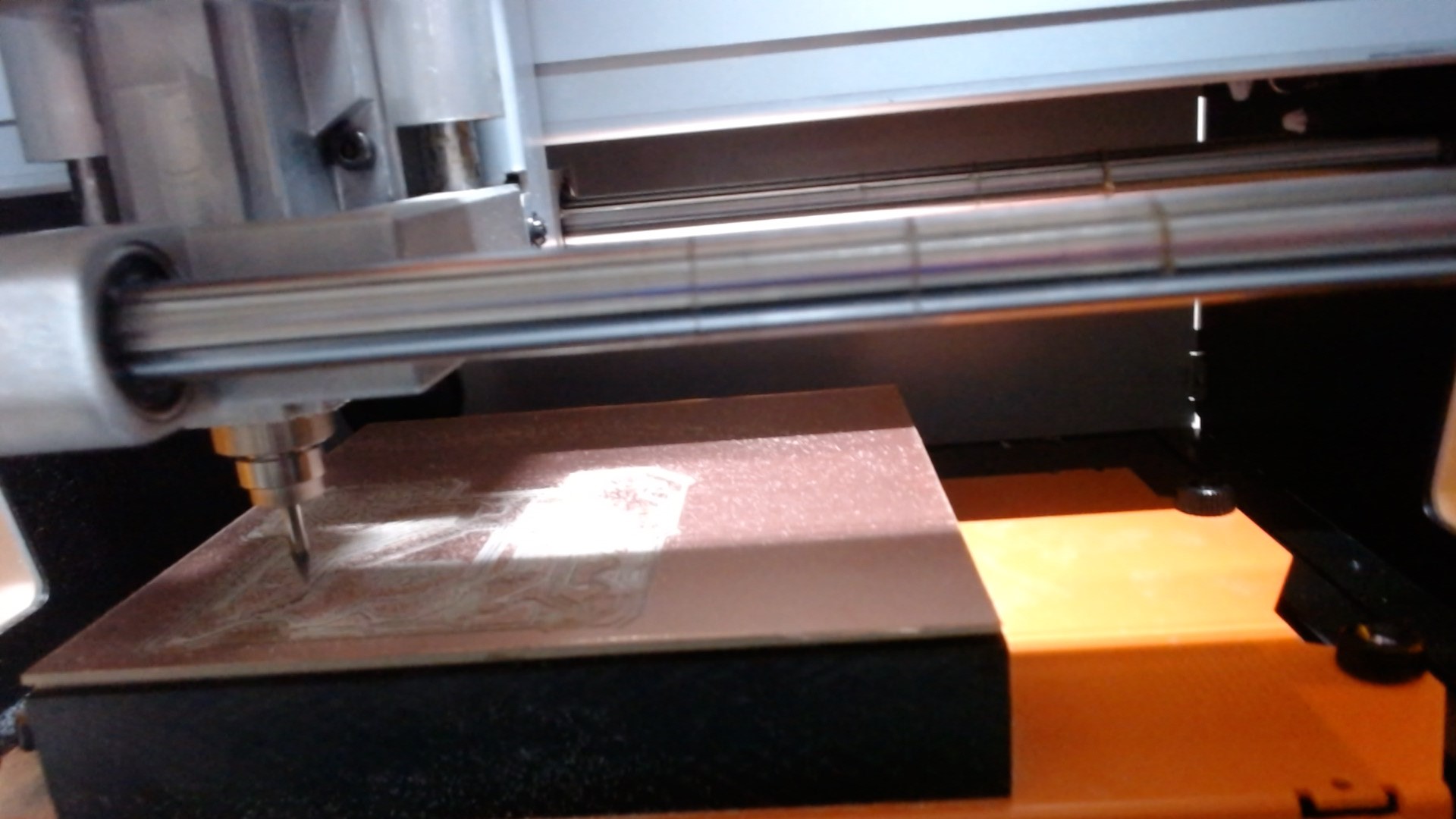
When I tried to generate the the rml file by exporting the png file at 1000 dpi but it resulted to shorts in the traces of the ESP32. Hence to get a correct toolpath we exported the file at 1000.05 dpi.
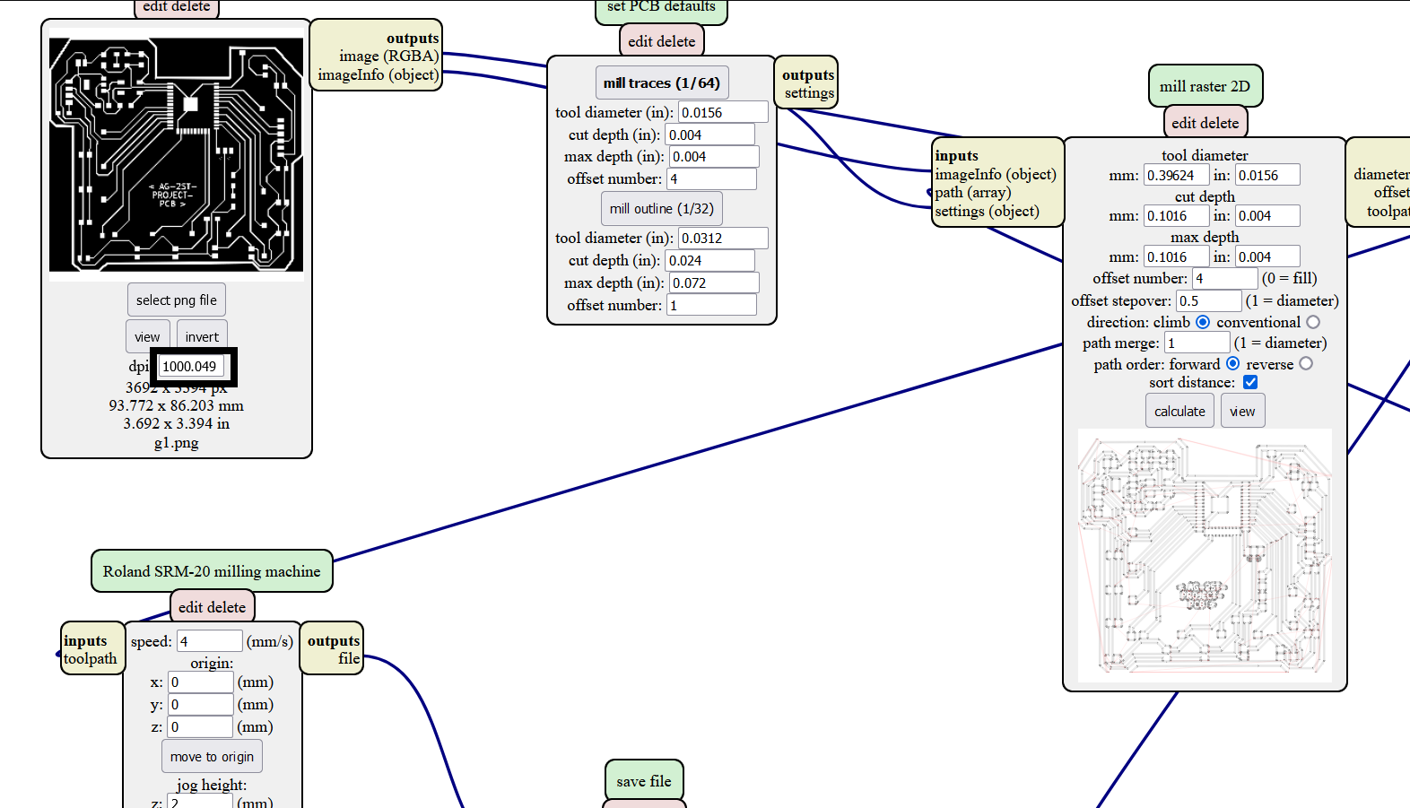
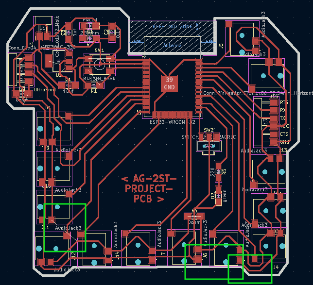
And the tool path generated has no short circuit between the pads especially ESP32’s.
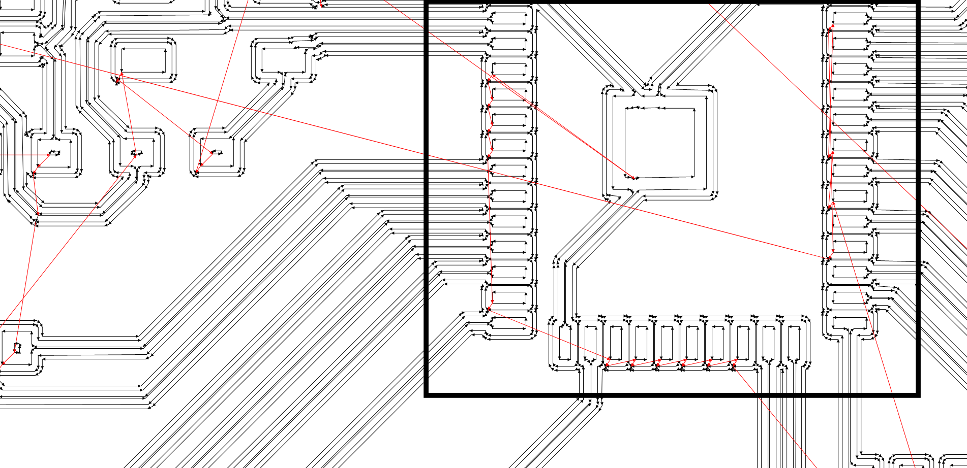
The image below is output of all the worl done. The boxes markes the no connection between the traces of Vcc and ground.
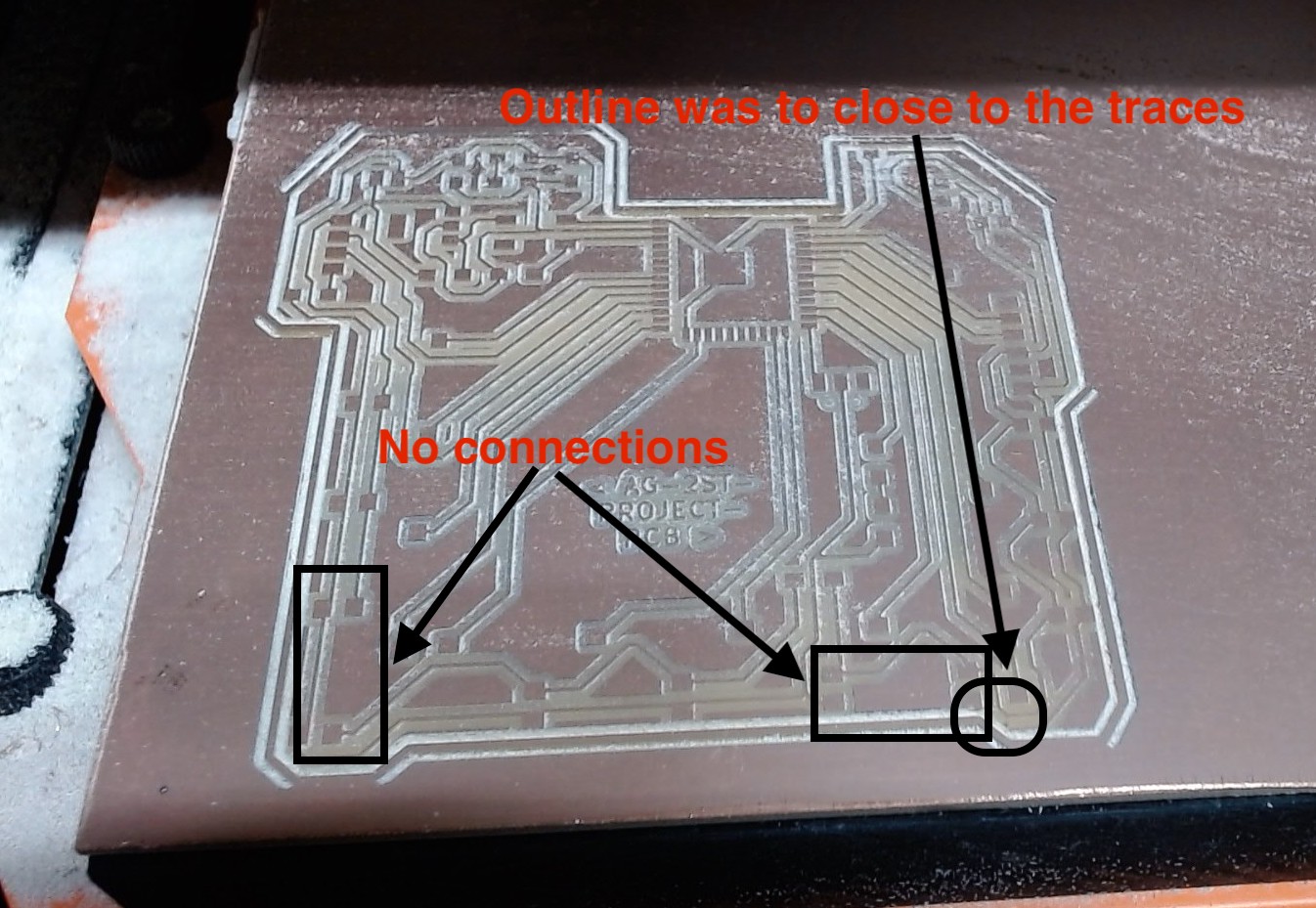
To overcome this issue, small improvising works are done. such as: - Vin connection with the Vcc of the FTDI connector header. - Ground Connections.
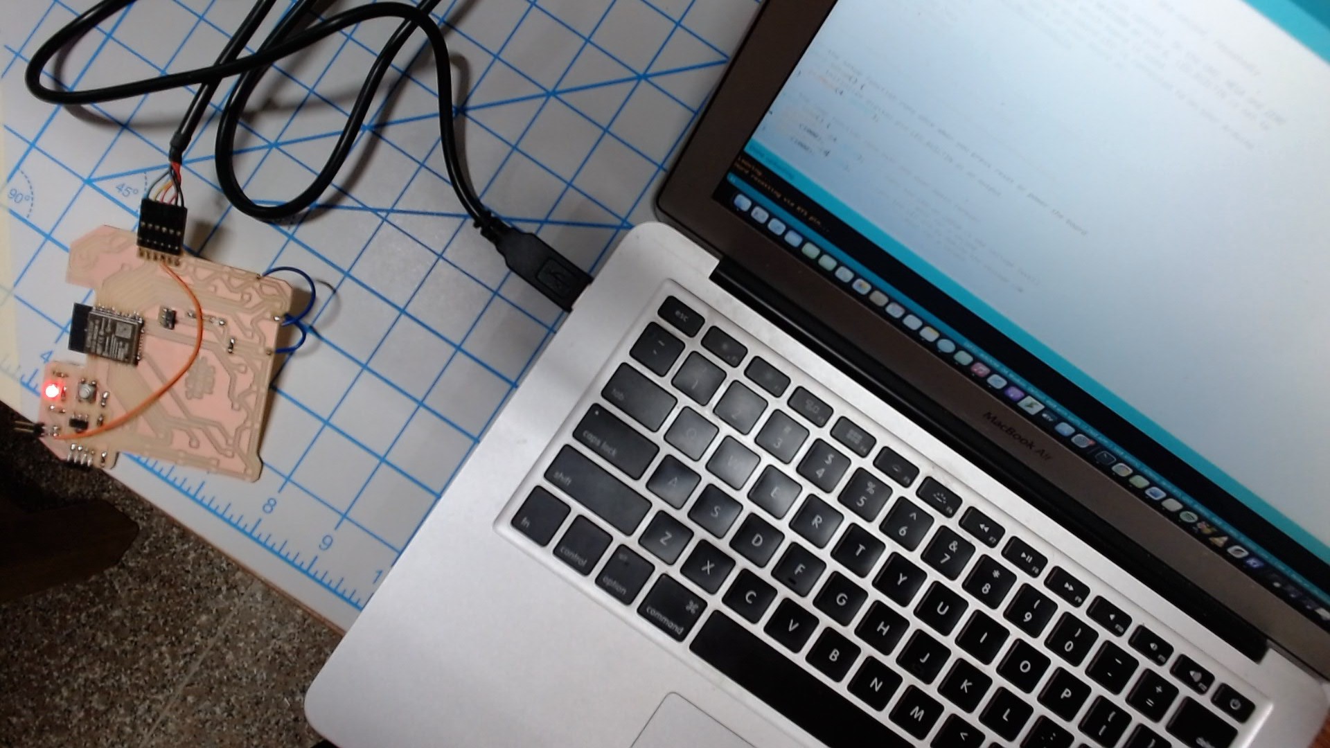
Testing of board.
To test the board, when I connected the FTDI programmer the power LED glowed.
The the next step was to check if the ESP32 can be programmed or not. Since the board is designed with a programmable LED connected to the GPIO 4, we can test the board by trying to control the LED.
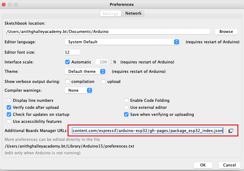
First step here is to add the ESP32 board to the Arduino IDE platform.
- Add the esp32 board link in the preferences after adding a comma.
- Link:
https://raw.githubusercontent.com/espressif/arduino-esp32/gh-pages/package_esp32_index.json
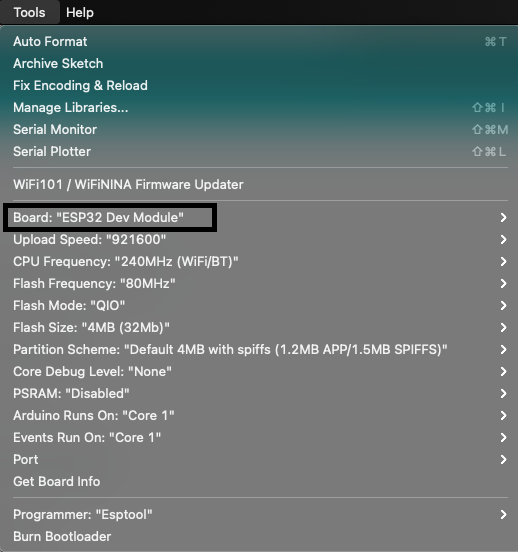
- Next, from the board manager install the ESP32 boards to the IDE.
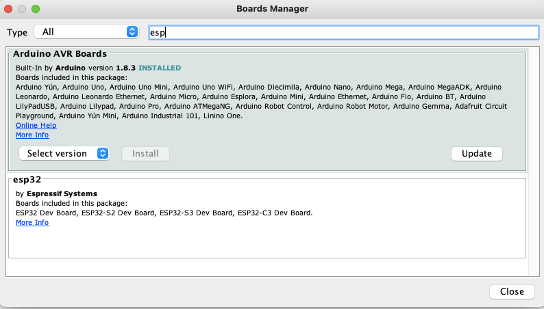
- Then making sure the right ESP32 board is selected in the tools tap.
When I uploaded the blink code the LED connected to GPIO 4 started to blink.
Add the blink video
Wireless Network.
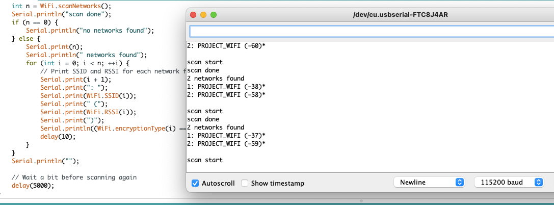
- Test to Scan the wifi Networks available. File: Examples -> Wifi -> Wifiscan.
- And then I tried to create a webserver using the ESP32 board. The web will enable the user to control the boards LED by connecting the common network.
- I referred this Link on ESP32. And followed a tutorial to create a standalone Web Server.
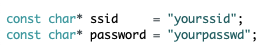
A simple code to create a web server is available in the in Example -> Wifi -> Simple Webserver. We just have to Replace with your network credentials.
 // Display the HTML web page
            client.println("<!DOCTYPE html><html>");
            client.println("<head><meta name=\"viewport\" content=\"width=device-width, initial-scale=1\">");
            client.println("<link rel=\"icon\" href=\"data:,\">");
            // CSS to style the on/off buttons
            // Feel free to change the background-color and font-size attributes to fit your preferences
            client.println("<style>html { font-family: Helvetica; display: inline-block; margin: 0px auto; text-align: center;}");
            client.println(".button { background-color: #4CAF50; border: none; color: white; padding: 16px 40px;");
            client.println("text-decoration: none; font-size: 30px; margin: 2px; cursor: pointer;}");
            client.println(".button2 {background-color: #555555;}</style></head>");

            // Web Page Heading
            client.println("<body><h1>ESP32 Network</h1>");

            // Display current state, and ON/OFF buttons for GPIO 26
            client.println("<p>GPIO 4 - State " + output4PinState + "</p>");
            // If the output26State is off, it displays the ON button
            if (output4PinState=="off") {
              client.println("<p><a href=\"/4/on\"><button class=\"button\">ON</button></a></p>");
            } else {
              client.println("<p><a href=\"/4/off\"><button class=\"button button2\">OFF</button></a></p>");
            }
            client.println("</body></html>");

            // The HTTP response ends with another blank line
            client.println();
This block of code will be inside the void loop to create a User interface with a button to control the glowing of the LED connected to the GPIO 4.
The interface for the user will be as shown below.
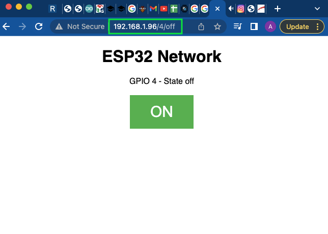
The code can be found at the end this page. After the code is uploaded, switch the slide switch to the run mode and power the agian and open the serial monitor and press the button switch connected to the enable Pin of the ESP32. When the module is conected to the network the interface can be accessed from the IP address given.
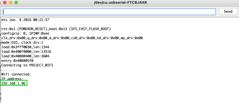
And from the browser we can access the webserver with some interface, provided connected to the same network. The vide