Week 13: Communication and Networking - Group Assignment
Netwoking and communication plays the crucial role in the electronics world. People communicate between long distance using communication technique of elctronics. This week is about learning how communication is happening between two or more electronics components or devices.
Instruction:
Group Assignment:
Send a message between two projects
Communication Types
Wired Communication:
Wired communication refers to the transmission of data over a wire-based communication technology. Wired communication is also known as wireline communication. Wiki
SPI
Serial peripheral interface (SPI) is one of the most widely used interfaces between microcontroller and peripheral ICs such as sensors, ADCs, DACs, shift registers, SRAM, and others. This article provides a brief description of the SPI interface followed by an introduction to Analog Devices’ SPI enabled switches and muxes, and how they help reduce the number of digital GPIOs in system board design.
SPI is a synchronous, full duplex main-subnode-based interface. The data from the main or the subnode is synchronized on the rising or falling clock edge. Both main and subnode can transmit data at the same time. The SPI interface can be either 3-wire or 4-wire. This article focuses on the popular 4-wire SPI interface. https://www.analog.com/en/analog-dialogue/articles/introduction-to-spi-interface.html

I2C Communication:
I2C combines the best features of SPI and UARTs. With I2C, you can connect multiple slaves to a single master (like SPI) and you can have multiple masters controlling single, or multiple slaves. google
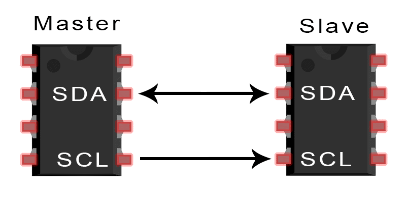
SDA (Serial Data) – The line for the master and slave to send and receive data.
SCL (Serial Clock) – The line that carries the clock signal.
Wireless Communnication:
Wireless Communication is a method of transmitting information from one point to other, without using any connection like wires, cables or any physical medium.
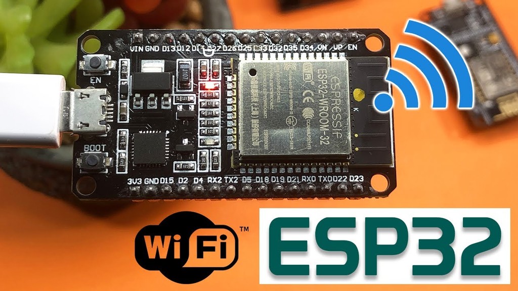
WiFi
In electronics, we can communicate through hte wifi using wifi ssid and pssword. Some controllers like ESP have the in built wifi module while other controllers like arduino and attiny require external wifi module connection.
From Google
Bluetooth Communnication:
We can also communicate through the Bluetooth connection. Bluetooth are usually connected as master and slave inorder to let them communicate. Data sender are master and the one receiving the data are slaves.
ESP board have bluetooth module in built while arduino and attiny requires external module connection.
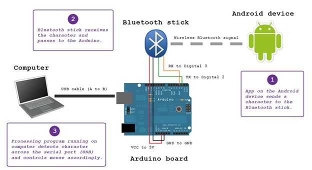
Bluetooth communication From Google
Communicating between Boards:
There are many ways to let communication between the boards. Since most of us use ESP as project board, we tried to communicate between multiple esp boards.
Two Boards Communicating in Both Ways:
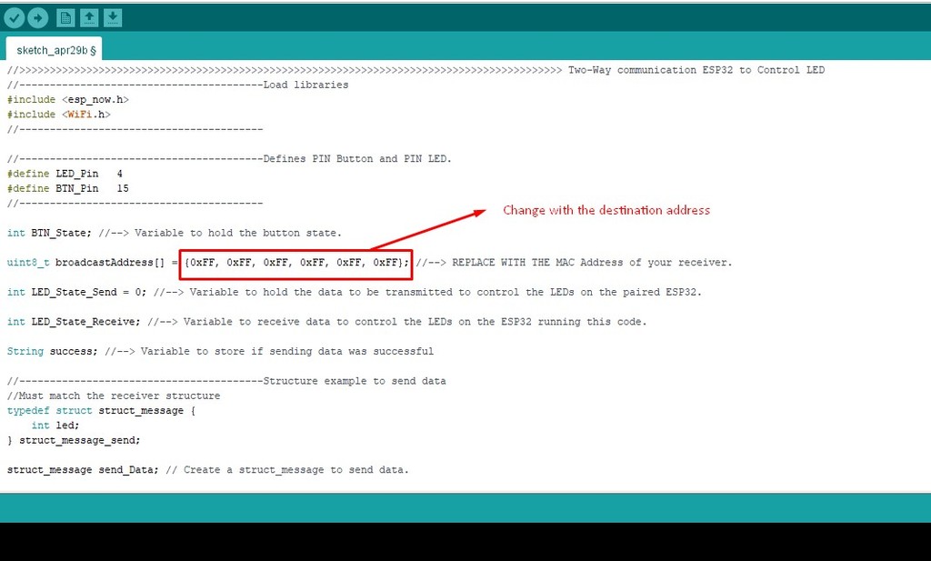
For the two boards to communicate with each other, we need to find out the macAddress for each of them. The boards communicate with each other through the given address.
	#include "WiFi.h"
	void setup() {
	  Serial.begin(115200);
	  WiFi.mode(WIFI_MODE_STA);
	  Serial.println(WiFi.macAddress());
	}
	void loop() {
	}
Code to find out the address of from each port.
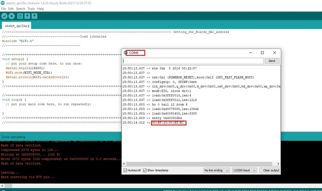
Finding address of ESP32 on COM port 4
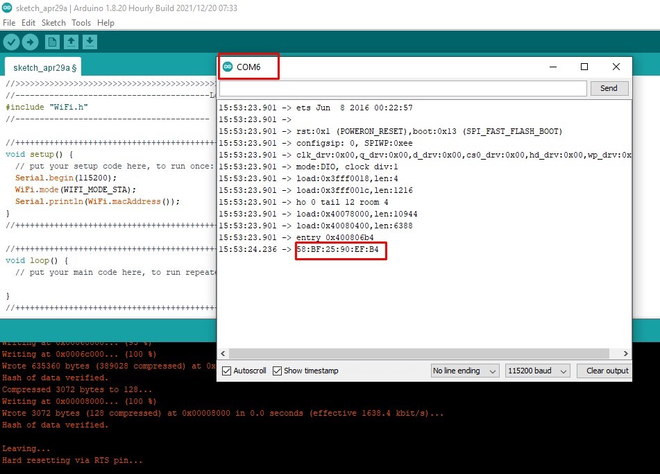
Finding address of ESP32 on COM port 6
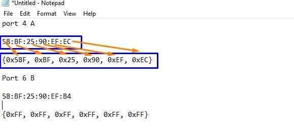
Once I got the address, I changed it into required format as shown in above. These address we need to replace in the program as the address of destination.
Communication between Three Boards:
Once communicating between two boards get successful, we tried for communicating between three boards.
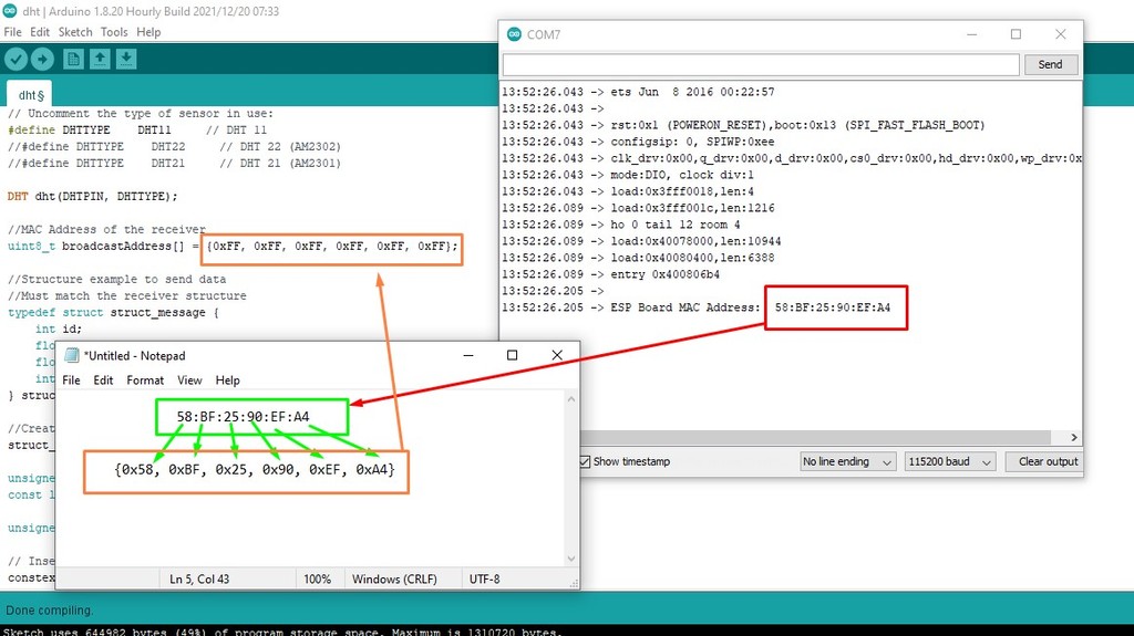
First, we find the macaddress of the receiver esp, made it into required format and replaced in the sender as shown in above image.

We loaded the program into the receiver and sender respectively and tried to see if it get connected. Unfortunately, it couldn't get connected into the required channel. Program is in such a way that sender scans for the channel of the receiver and send data through the channel.
Receiver channel get activated at channel 3 while sender gets onto channel 11 as shown.
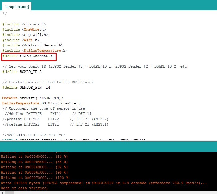
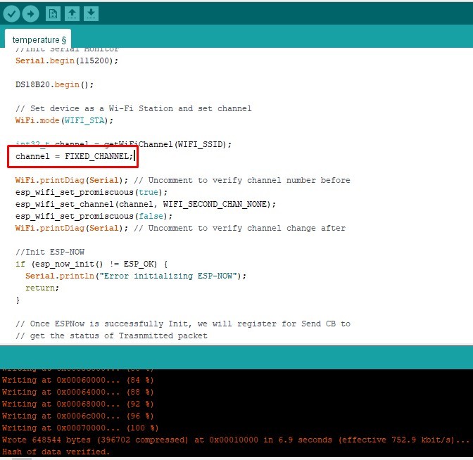
For that we need to define the fixed channel to 3 for the sender and gave the fix channel to the channel variable in the code as above.
Actually the channel is variable which will be filled after scanning, but as it doesn't work, we need to fixed the vriable channel to channel number 3 to get synchronize with the receiver channel.
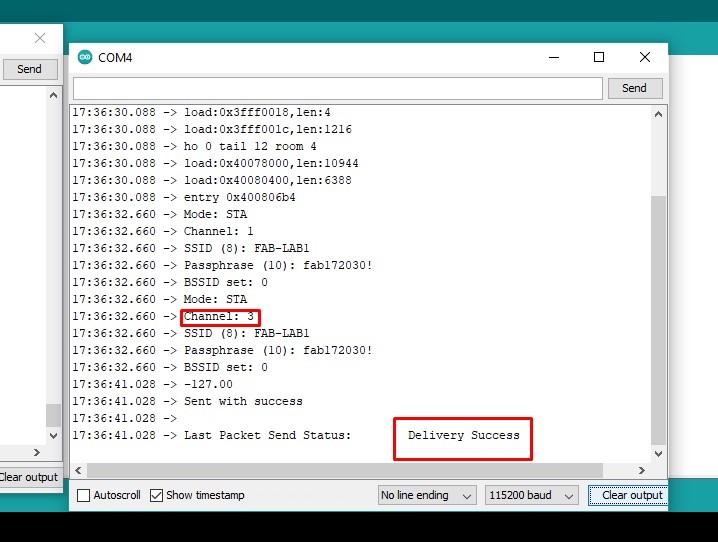
That fixed the problem that we were having earlier and message from sender got successfully sent.
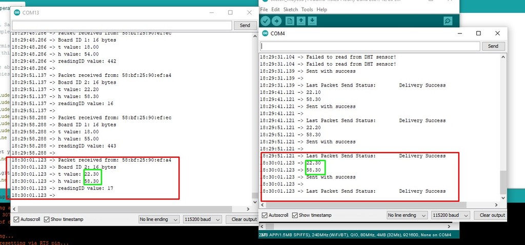
Next changing the board address to 2, we loaded the same code to another sender and tried to transmit the data from second board to receiver.
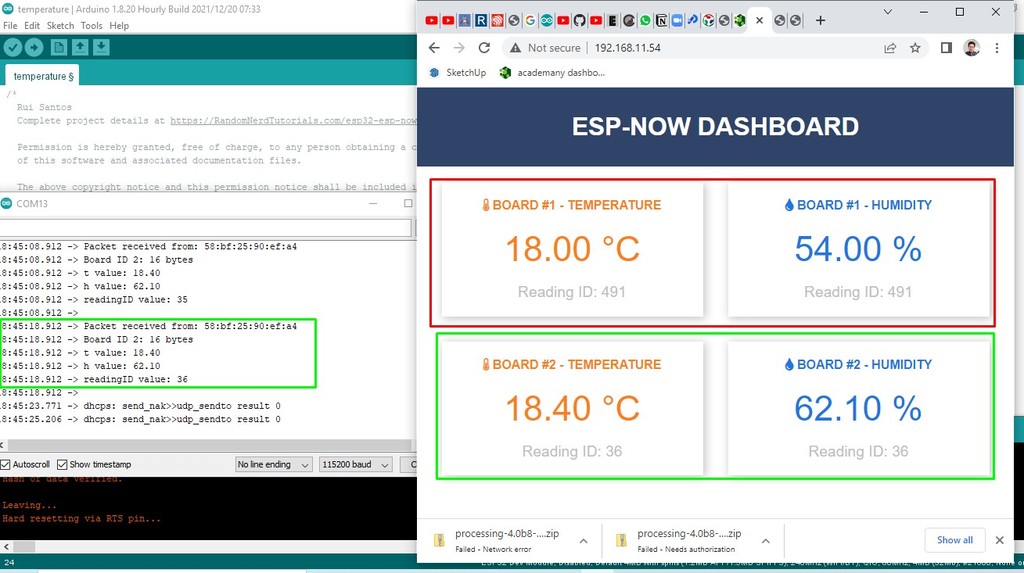
From the IP Address generated from the receiver, we open it in the web browser.
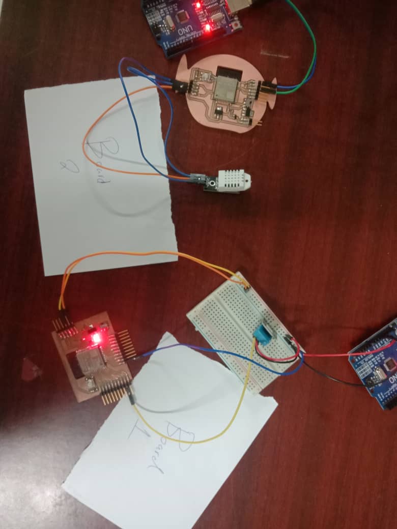
Sender Boards
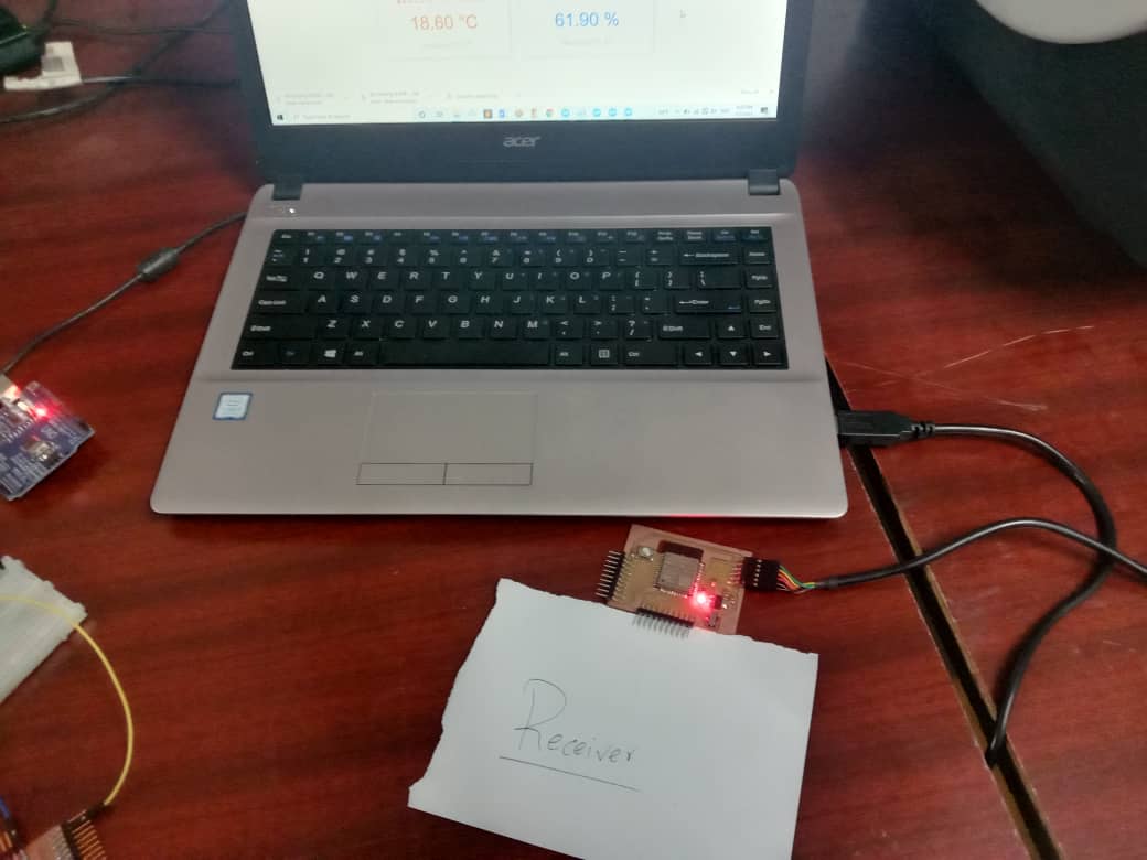
Receiver board
Reference
- Bluetooth Communication: https://www.c-sharpcorner.com/UploadFile/167ad2/how-to-use-hc-05-bluetooth-module-with-arduino/
- Wired Communication: https://en.wikipedia.org/wiki/Wired_communication#:~:text=Wired%20communication%20refers%20to%20the,%2C%20and%20fiber%2Doptic%20communication
- ESP Tutorials: https://randomnerdtutorials.com/