Final Project - 2022
Project is the part of Fab Academy where every student must complete in order to graduate. We were asked to submit project topics during pre-fab academy looking at the local issues that we are facing. Find my proposed topic with brief explanation here.
Topic - Automatic cross walk signal
As the country is constantly developing, number of cars on the street keeps on increasing which also increases the traffic accidents usually while pedestrian crosses the road. There should be some understanding between the road users in order to minimize the accident occurring.
Usually in my country there is no traffic signal and traffics are controlled by traffic police standing at the cross road or where people need to cross. Otherwise, traffic will get jammed for an hour or much longer. It not only consumes the human resources but also cause inconvenience while having to control manually.
There are lots of traffic lights commercially where the signal changes with specific time difference or some controlled by centralized place by traffic police or person, monitoring through camera. Some are much better which are controlled automatically by sensors making it more convenient.
Though my project may not be comparable to those produce from manufacturers, but with my simple idea, I will try to make automatic cross walk signal that can solve the local problem with the minimum cost.
Project Description:
- Input
- It will be more durable over switches or button. Repeated touch or push of button will add to ware and tear faster than sensor.
- It will be safer from virus and diseases. Even in current situation, corona virus is spread through body contact. Not only in current situation but it can also prevent many skin and other transmittable diseases as we are not having direct contact.
In this assignment I will use sensors as an input where pedestrian who wanted to cross the road will trigger the sensor without having to touch or push. I selected the sensors over other physical buttons or switches because, as sensor can be trigger without having to touch it;
Controller
I planned to use fabricated micro-controller from Fablab in this project, but for this project to implement in the real field, it will require either wemos, or other stronger micro-controller as it will require to connect wirelessly between the two inputs from both side of the road.
This is in accordance where the pedestrians on either side of road needs to cross the road, they both require the access to sensors. In this project I can either connect with wires or wirelessly as the distance between two will be very less. But in field, the distance will be much longer.
Outputs
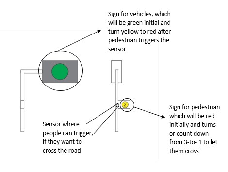
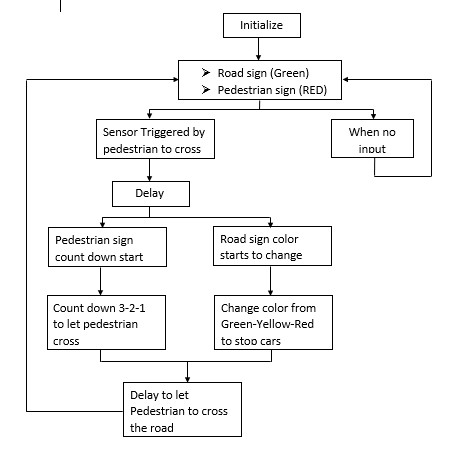
Output for this project should be separated into two, one for pedestrian and other for vehicles. Initially the sign for road will be green in order to let flow the traffic smoothly without disruption when there are no people who wants to cross the road and signal for pedestrian will be red.
When pedestrian comes to cross the road, they need to trigger the sensor which will let the controller to control the output. After triggering the sensor, with few delays, road sign will change to yellow and pedestrian sign will change (either count down or color change) in order to let the users, know. After few seconds, pedestrian sign needs to change to green letting people cross and road sign red stopping the vehicles.
Adding Features
As I keep on revising my project, there are a lot to incorporate in order to make it with better feature. The first basic is, pedestrians will not come from only one direction (from where the signal and sensors are). Therefore, people on other side of the road cannot have access to the facility and actually have to wait for the people on the sensor side to trigger the system in order to cross.
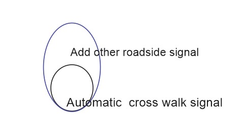
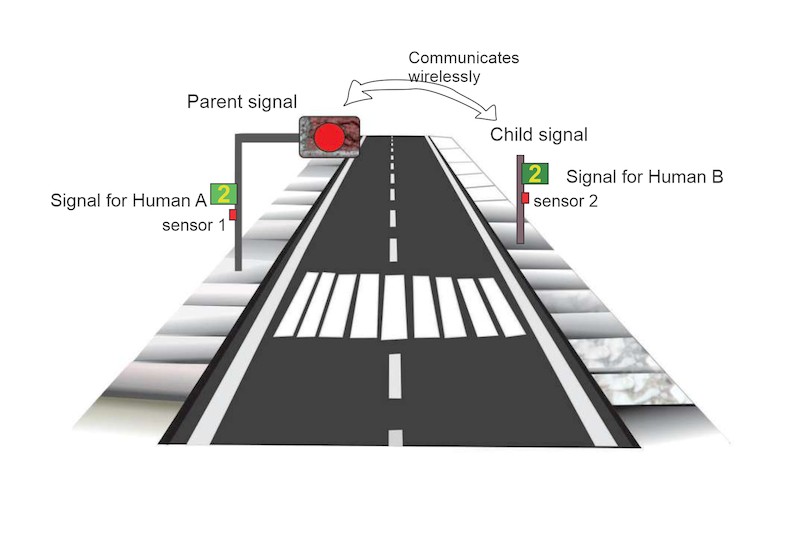
Therefore, I need to add sensor on other side of the road too along with the signal for the pedestrians. Since the vehicle users from both side of the road can see the road signal, for now I do away with the two road signal.
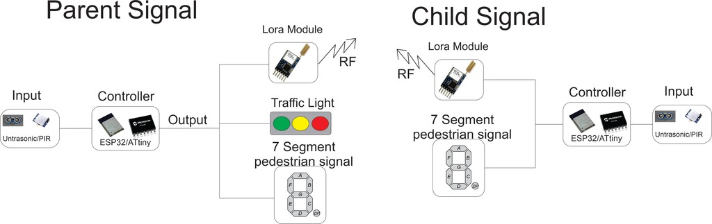
As the sensor and pedestrian sign on the both side of the road should work synchronously, they need to communicate with each other. For the communication, I am planning to use either LORA Module or ESP32 module while my controllers will be fabricated using ATtiny44.
Schematic Diagram
Answering:
What does it do?
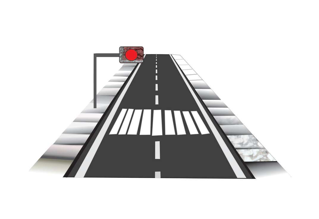
My project is highly focused on pedestrian cross point, which will give priority to pedestrian for crossing which is one of the key rules at the junction in the country. But it will also check the unnecessary hindrance of the flow of traffic.
My project is to control the pedestrian at the zebra cross point in order to increase the understanding between the road user and the people crossing the road.
Who's done what beforehand?
There are many traffic lights with different design as per their own requirement are already available in the market and almost all the countries in the world are using it to control traffic flows.
For the traffic light with the exact requirement in my country, me along with my bunch of friends are the first one trying to make it during our stay in FABLAB between 2017 August to 2019 February. We worked under the command from the mayor of Thimphu City who was Mr.Kinley Dorjee at the time. Due to budget and time limitation, project couldn't proceed as planned. So, my final project is also aimed at completing my long ago started project taking advantage of fabacademy.
What did you design?
I tried to keep it simple with advance functionality and exactly as per the requirement. Both side of the road will have human accessible sensor to trigger the cross walk sign. They function with respect to each other in order to lessen the confusion.
I designed the human interface to trigger the signal in order to match the requirement. Sometimes the crosswalk point remains empty when there is no pedestrian who wish to cross the road, at that time I don't want to disturb the traffic flow which the timing traffic light does. I also considered about pedestrian keeps on disturbing the road when there is more people wanting to cross the road.
What materials and components were used?
- To make road
- Plywood,
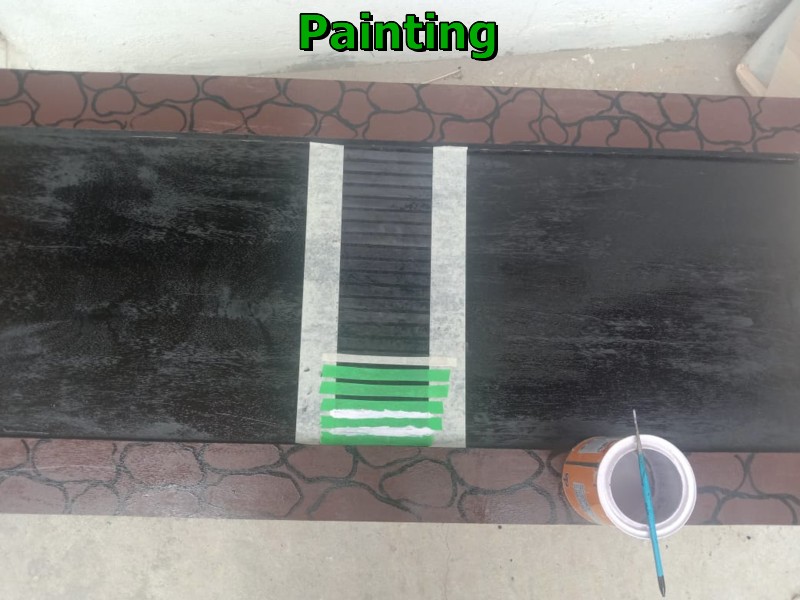
- Paints to paint the road
- Dish washing scrub to make trees for decoration
- For poll, led casing and 7segment casing
- 3D printing
- Ply Laser cut
- Electronics
- ESP32 as controller
- 7 segment LEDs
- Colored LED modules
- Ultrasonic sensors
- Resistors
- Capacitors
- Pin head connectors and wires
Where did they come from? How much did they cost?
Most of the components required were already there in the lab inventory. Few required to purchase where Suhas and Take our local instructor helped us get those.
| Sl.No | Items | Quantity | Source | Approx. Price |
|---|---|---|---|---|
| 1 | ESP32-WROOM-32 | 2 | Fab Inventory | Nu.920 |
| 2 | Ultrasonic sensor | 2 | Fab Inventory | Nu.525 |
| 3 | LED Big(Red, Green, Blue) | 1 each | Amazon.in | Rs.150 |
| 4 | Resistors | 6 | Lab Inventory | Nu.30 |
| 5 | Capacitors | 4 | Lab Inventory | Nu.30 |
| 6 | Jumpers | As per required | Fab Inventory | Nu.50 |
| 7 | 8mm plank/ply | 1 sheet | Local Sawmills | Nu.1000 |
| 8 | Small Buzzer | 2 | Amazon.in | Rs.100 |
| 9 | 7 segment 4 digit led | 2 | Amazon.in | Rs.460 |
| 10 | Miscellaneous | Fab Inventory | Nu.500 |
What parts and systems were made?
- Road model with system installed
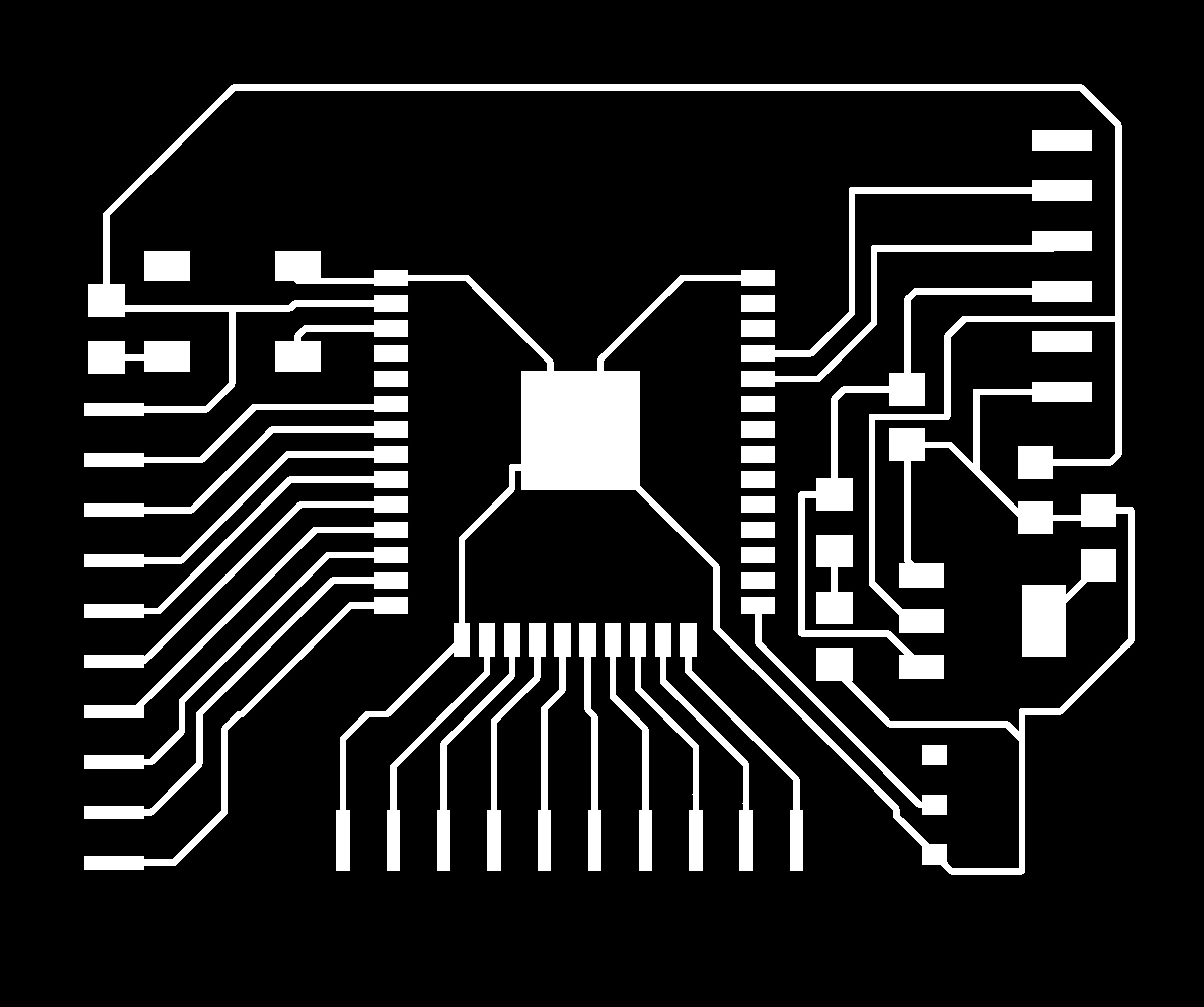
- Fabrication of Controller boards of ESP32-wroom
- Interfacing of input and output with controller
- Two board on two sides of the road works independently communicating through wifi
What processes were used?
| Sl.No | Particular | Process |
|---|---|---|
| 1 | Fabricating the main controller board from ESP32-WROOM-32 | PCB milling machine |
| 2 | Casing for the controller and LEDs | Laser cutter |
| 3 | Making road and structures of the project. | CNC machine and laser cutters |
| 4 | Polls for system and 7 Segment cases | 3D printer |
| 5 | Stickers of Bhutan flag on back side of road sign | Vinyl cutter |
| 6 | Soldering of components and making the circuitry | Soldering & Wiring |
What questions were answered?
My project is based on what is required the most. With my project system working and installed in the required place will minimize the misunderstanding between the road user and the one wanting to cross the road, which had been recently a major problem in my busy city.
What worked? What didn't?
Actually everything that I have planned worked well and even beyond. But one thing left is to try count the number of cars that are moving, using some sensor which will be another key feature of my project in future.
How was it evaluated?
It is evaluated based on how far I can advance with the prototype of my project. The physical model are just for the presentation while the main thing remains with the working system based on the real time.
What are the implications?
As it is on the practical basis and being one of the town's project I am planning to present to city mayor (Thrompoen) as I have already present to the JICA office in my country.
Also scale up to try in the real field even though its pretty sure it should work.
Fabrication Processes
Fabrication process is one of the main challenge for the project and time consuming one. I wanted to fabricate the whole system for the presentation. I tried to used every machines available in the lab during the prototyping.
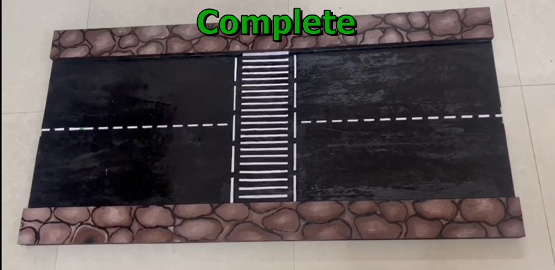
Road prototype using CNC
First to to make my model, I required the road. I used CNC machine to cut the parts as I require.


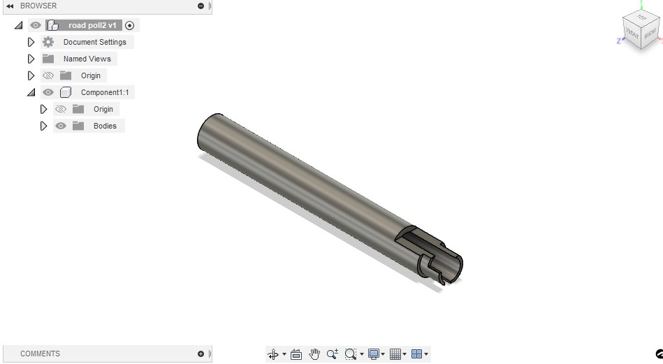
7 segment casing and poll using 3D printer
I used 3D printer in order to make my poll to install system on and casing of 7segment.
Designing 7Segment case
I also designed the polls of the traffic light in the 3D design too


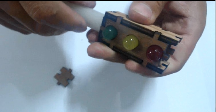
LED of traffic light casing using Laser
I made use of laser cutting machine to make the casing for traffic light.
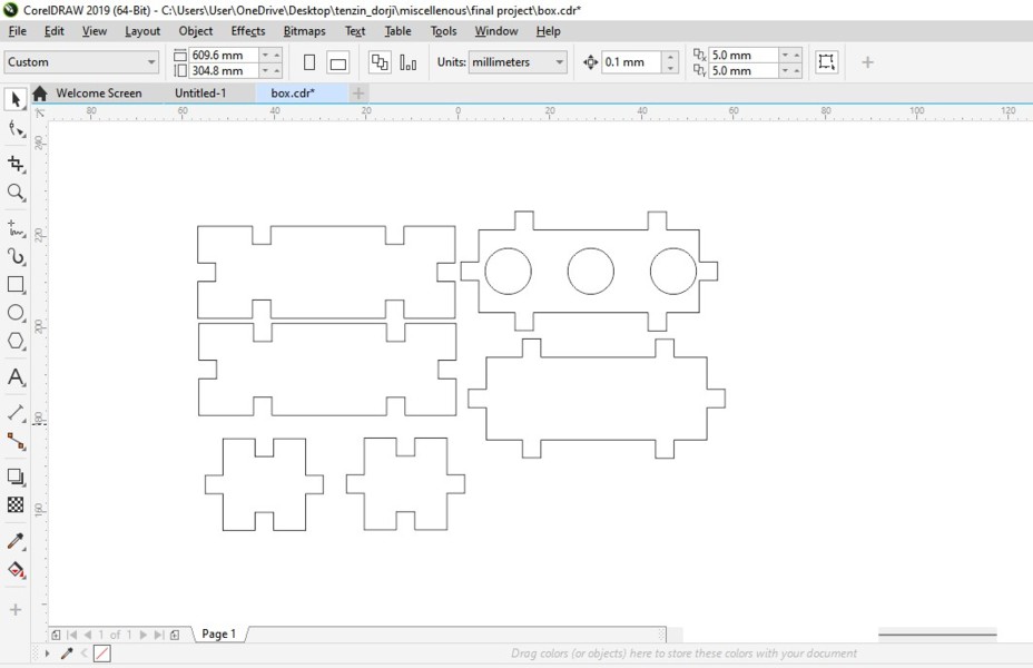
I measured all the dimensions required designed in the corel draw as per. After that I cut it in the laser machine and product is as below.
Sticker of National flag from Vinyl cutter
Its one of my most satisfied make during my project creation. I get to design and print Bhutan national flag in vinyl cutter.
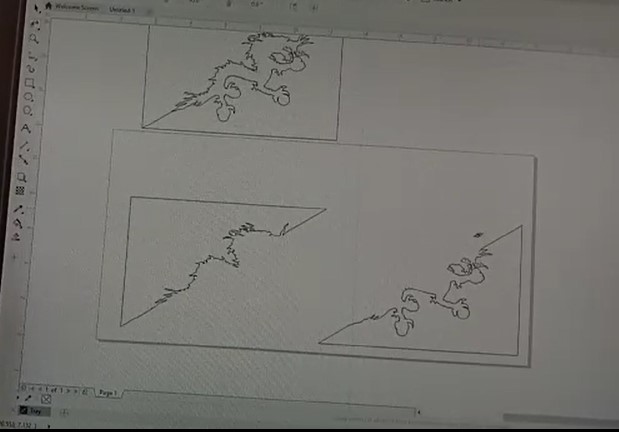
Bhutan flag consists of three part, upper yellow part diagonally half, middle white dragon and lower another half of orange color. So in order to get all that color, I have to design every parts separately.
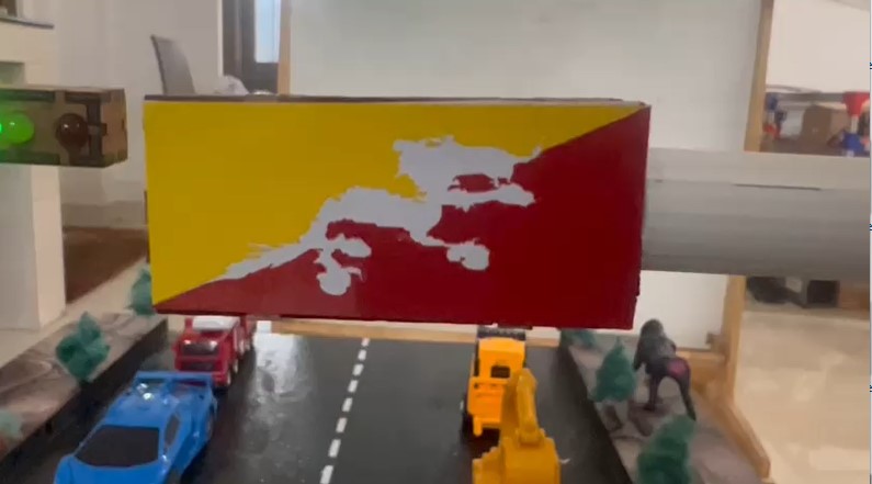
Not really perfect but satisfactory
Electronics and Programming
For my final project, I need to use the controller that we fabricate ourselves. More on controller fabrication, visit my week 10 assignment Linked here.
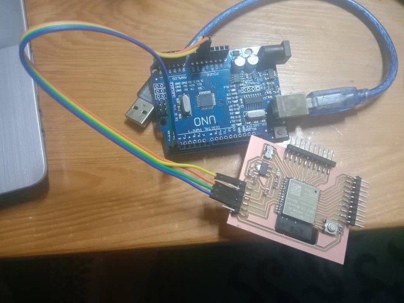
I used Arduino as FTDI to program my ESP board. Unlike ATtiny, ESP32 doesn't require programmer, instead it uses FTDI programmer. So, we need to make Arduino as FTDI by either
- Shorting the EN and GND of the Arduino,
- Removing the IC of the Arduino or
- Loading the blank program to the Arduino.
I preferred loading program to the Arduino to make it as FTDI.
	void setup(){
	pinMode(0,INPUT);
	pinMode(1,INPUT);
	}
	void loop(){
	}
This is simple arduino code that makes RX and TX pin of the arduino as output pin. Load this code to arduino that you are going to use as FTDI. More detail on the output interface and 7 segment fabrication visit my Output week assignment
Testing of code and controller
Pedestrian Interfacing
After the successful testing of various input and output with my final project boards, it's time to test some more complicated things. The first thing I wanted to try is interfacing for the pedestrian for crossing the road.
Get more details from Input Device week and Networking and Communication week assignment.
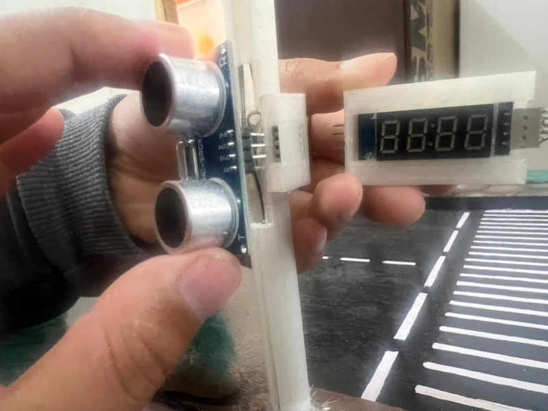
I am going to use ultrasonic sensor as button to trigger the system when pedestrian wants to cross the road. People should know that their triggering was successful, so I added buzzer to notify when they successfully triggered the system.
After the system get triggered, system need to give some time for the road users to prepare for stopping in order to let people pass the road.
For that I gave countdown for pedestrians to wait for few seconds before crossing the road using 7 segment leds.
My code as below
//source code from:https://lastminuteengineers.com/tm1637-arduino-tutorial/
//Edited by: Tenzin Dorji


#include <TM1637Display.h>

#define CLK 27
#define DIO 14

const int trigPin = 2;
const int echoPin = 15;
const int ButtonPin = 13;

// Create a display object of type TM1637Display
TM1637Display display = TM1637Display(CLK, DIO);

// Create an array that turns all segments ON
const uint8_t allON[] = {0xff, 0xff, 0xff, 0xff};

// Create an array that turns all segments OFF
const uint8_t allOFF[] = {0x00, 0x00, 0x00, 0x00};

// Create an array that sets individual segments per digit to display the word "-GO-"
const uint8_t go[] = {
  SEG_G,                                            // -
  SEG_A | SEG_G | SEG_C | SEG_D | SEG_B | SEG_F,    //g
  SEG_A | SEG_B | SEG_C | SEG_F | SEG_D | SEG_E,    // O
  SEG_G,                                            // -
};

const uint8_t Stop[] = {
  SEG_A | SEG_G | SEG_F | SEG_D | SEG_C,            //S                                         // -
  SEG_F | SEG_G | SEG_E | SEG_D,                    //t
  SEG_A | SEG_B | SEG_C | SEG_F | SEG_D | SEG_E,    // O
  SEG_A | SEG_B | SEG_G | SEG_F | SEG_E,             //P                               // -
};


//define sound speed in cm/uS
#define SOUND_SPEED 0.034
#define CM_TO_INCH 0.393701

long duration;
float distanceCm;
float distanceInch;

void setup() {
  Serial.begin(115200); // Starts the serial communication
  pinMode(trigPin, OUTPUT); // Sets the trigPin as an Output
  pinMode(echoPin, INPUT); // Sets the echoPin as an Input
  pinMode(ButtonPin, OUTPUT);
}

void loop() {
  display.clear();
  delay(500);
  display.setSegments(Stop);
  // Clears the trigPin
  digitalWrite(trigPin, LOW);
  delayMicroseconds(2);
  // Sets the trigPin on HIGH state for 10 micro seconds
  digitalWrite(trigPin, HIGH);
  delayMicroseconds(10);
  digitalWrite(trigPin, LOW);

  // Reads the echoPin, returns the sound wave travel time in microseconds
  duration = pulseIn(echoPin, HIGH);

  // Calculate the distance
  distanceCm = duration * SOUND_SPEED/2;


  // Prints the distance in the Serial Monitor
  Serial.print("Distance (cm): ");
  Serial.println(distanceCm);

  if(distanceCm<8){
    countdown();
      int j = 0;
       while (j<20){
          display.setSegments(go);
          delay(500);
          display.clear();
          delay(500);
          j++;
      }
    }
  delay(500);
}

void countdown(){
  display.setBrightness(5);
  // Set all segments ON
  display.setSegments(allON);
  digitalWrite(ButtonPin, HIGH);

  delay(2000);
  digitalWrite(ButtonPin, LOW);
  display.clear();

   int i;
  for (i = 5; i >= 0; i--) {
    display.showNumberDec(i);
    delay(1500);
  }

}
System Integration
After the successful test and building of model, it's time for integration, bringing together all the parts and system. Main integration requires is the installing of electronics system on the physical model.
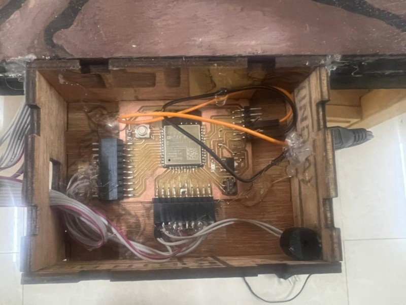
I placed the main controller inside the laser made box and used some female connector head to connect peripheral components.
For cleaner connection, I passed all jumpers connectors through the poll and tried to make everything easily removable for transportation. But due to some reason, I couldn't achieve all of that.
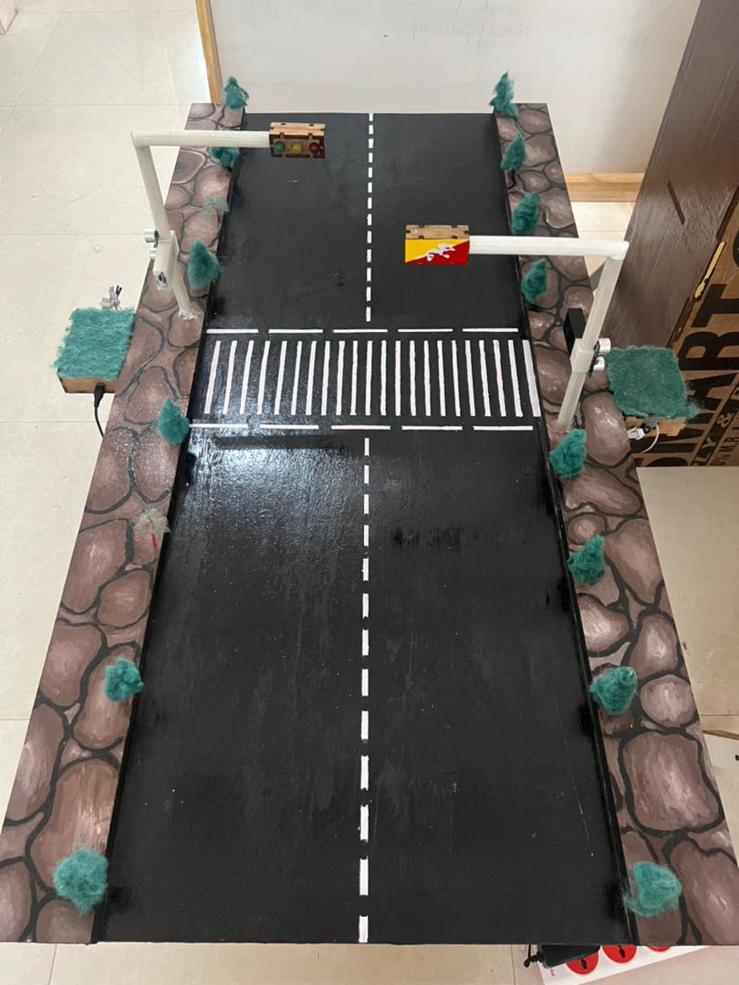
Final model
Final Product
Project Presentation Slide
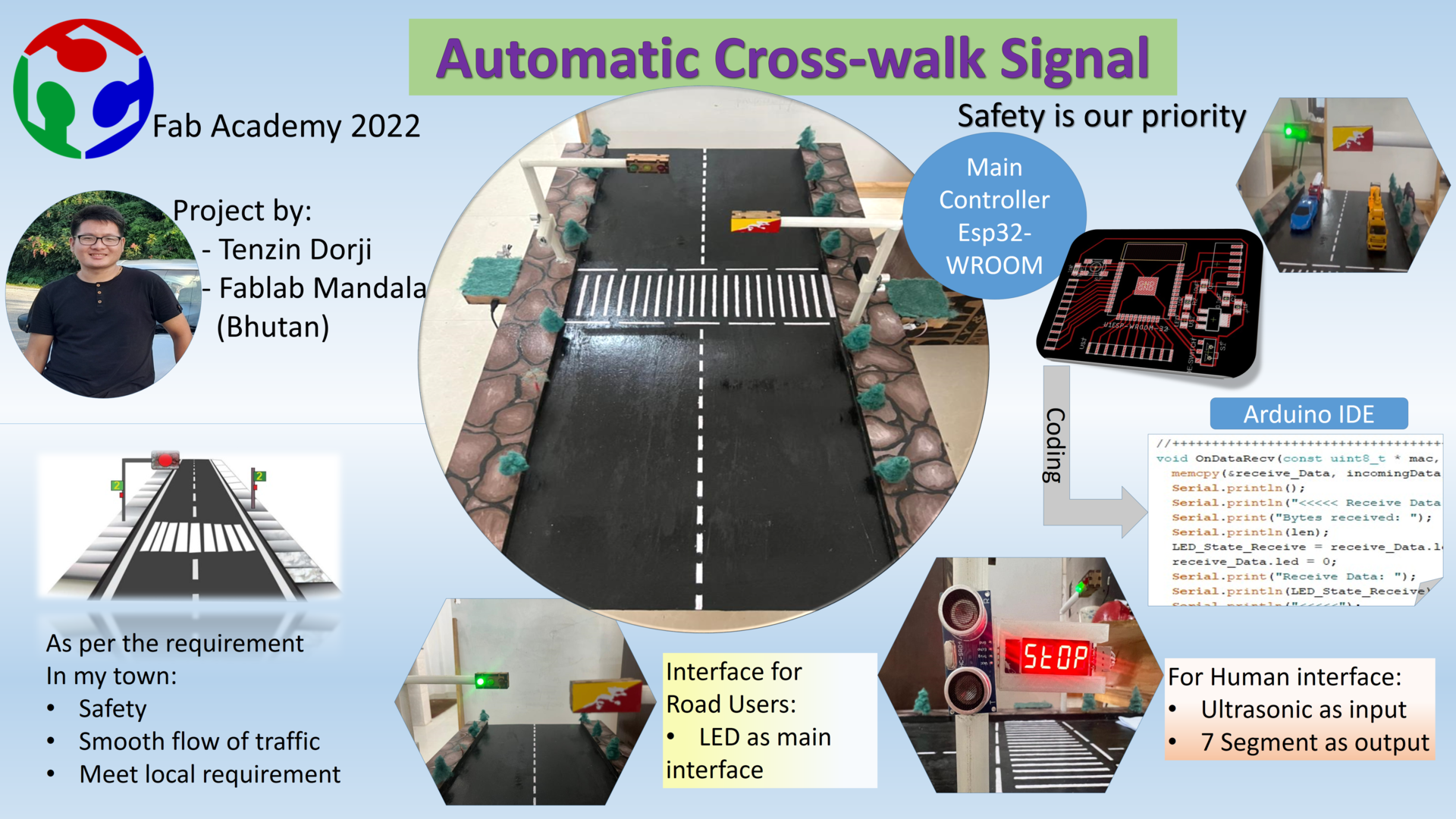
Project presentation Video
Final presentation of my project
Me presenting my project to JICA
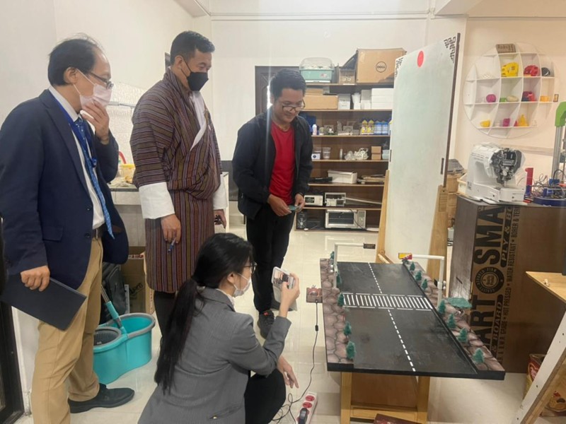
From front side:
Ms. Kozue Kato, Country Officer, South Asia Division 1, JICA HQ
Mr. Masayoshi Kawai, Project Formulation Advisor, JICA Bhutan
Mr. Krishna Subba, Chief Program Officer, JICA Bhutan
Finally on the other end is me
- Design Files
- Main controller trace file Here
- Main controller outline file Here
- Main controller board & Schematic file Find here
- 3D casing for 7 segment file Here
- 3D horizontal poll file Here
- 3D vertical poll 1 file Here
- 3D poll clamp file Here
- 3D vertical poll 2 file Here
- Laser file for controller box Here
- Laser file for traffic LED cover Here
Reference
- 7 Segment Programming https://www.circuitgeeks.com/arduino-7-segment-display-tutorial/
- 7 Segment resources https://lastminuteengineers.com/tm1637-arduino-tutorial/
- Ultrasonic sensor resources https://randomnerdtutorials.com/esp32-hc-sr04-ultrasonic-arduino/