Week 12: Input Device
Input device of electronics are the electrical equipment that transform the physical or external energy into electrical pulses.
We use Input device in Electronics to communicate between the human and the output devices. Input Device can sense the comment from external and pass to controller in order to let the putput device function in the required ways.
Instruction:
measure something: add a sensor to a microcontroller board that you have designed and read it.
Group Assignment:
Probe an input device's analog levels and digital signals
- To Do:
- Learn about Input devices.
- Design controller for my output device (ESP32 board).
- Learn to program my controller.
- Program and control my input devices.
- Document on what I learn through this week
- Group Assignment.
Useful Links:
ESP32 Library for eagle here
ESP32 tutorial resources Here
Input Devices:
An input device responds to changes in the environment and produces a suitable electrical signal for processing in an electronic circuit.
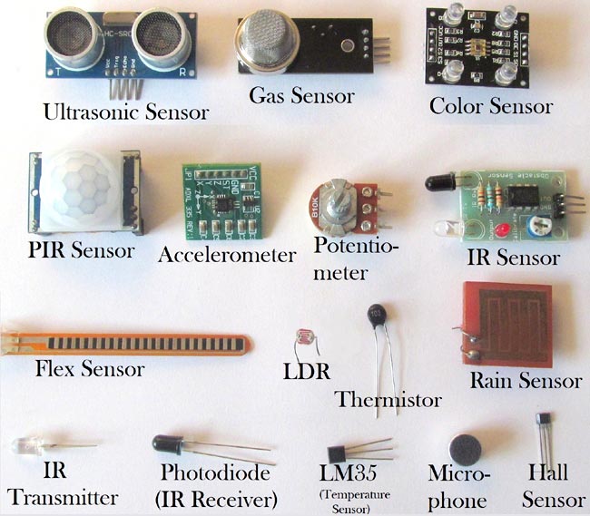
There are various types of input devices with specific function. Each input device responds to specific change in the environment and convert it into suitable electrical pulses.
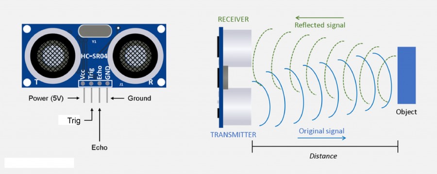
For this week assignment, I used ultrsonic sensor to check as input device as I require it for my final project.
Ultrasonic sensor have two parts, one for sending the signal and another to receive the echo signal which bounce back from the distance object.
It works based on the signal travel and return to the sensor, calculating the time between the signal sent and signal return.
Controller Fabricating:
I fabricated my esp32 board for my final project and OutPut/Input Devices during week ten of output device week. I also added the documentation here in order for easy reference.
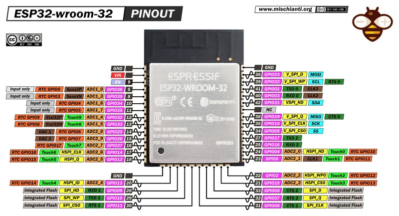
The basic requirement circuit to fabricate ESP32 WROOM as controller is given here. Find under ESP32 heading.

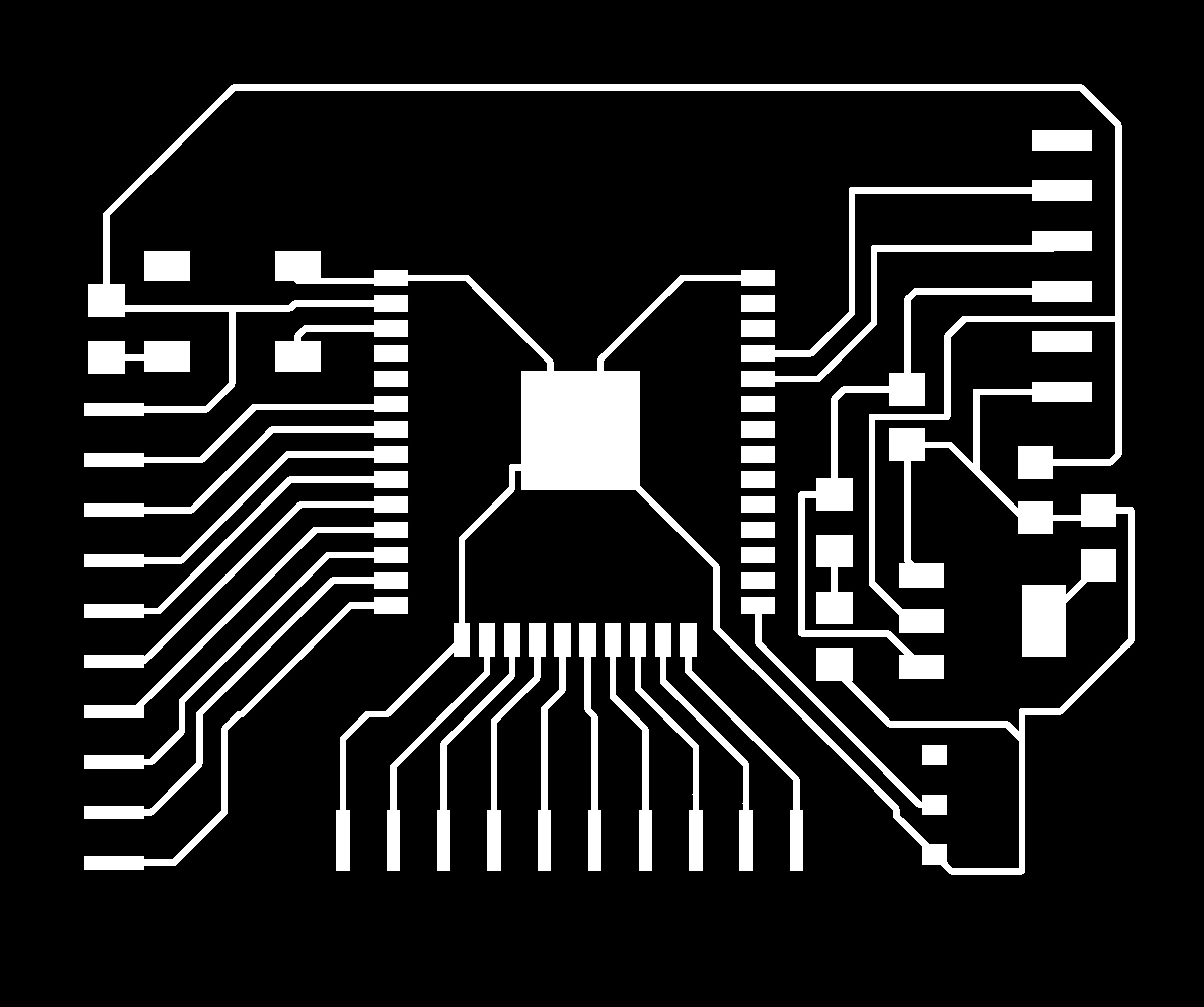
I designed circuit board as per minimum circuit required for esp32 and added some free pinouts so that I can program the pins later.
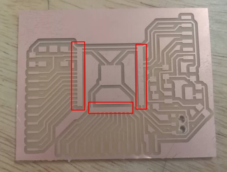
After the designing and exporting, I tried milling in the cnc milling machine and find out that pins of the esp32 were not printed. Iknew that I overlooked the view given in the mods.
Consultation with instructor found out that I need to change the pad size of the pins of the esp controller in the eagle library.
Doenload esp32 library of eagle from Here.
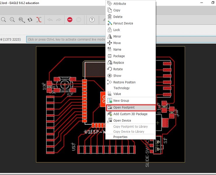
In order to change the pad size, Right click on the component and select Open Footprint to change it.
On the top, in the comment box, type change smd and enter to get drop down.
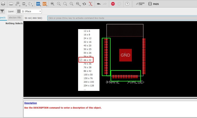
From the dropdown, select 66*32 usually it works for esp32 controller. After selecting, we need to select pins one by one to get changed.
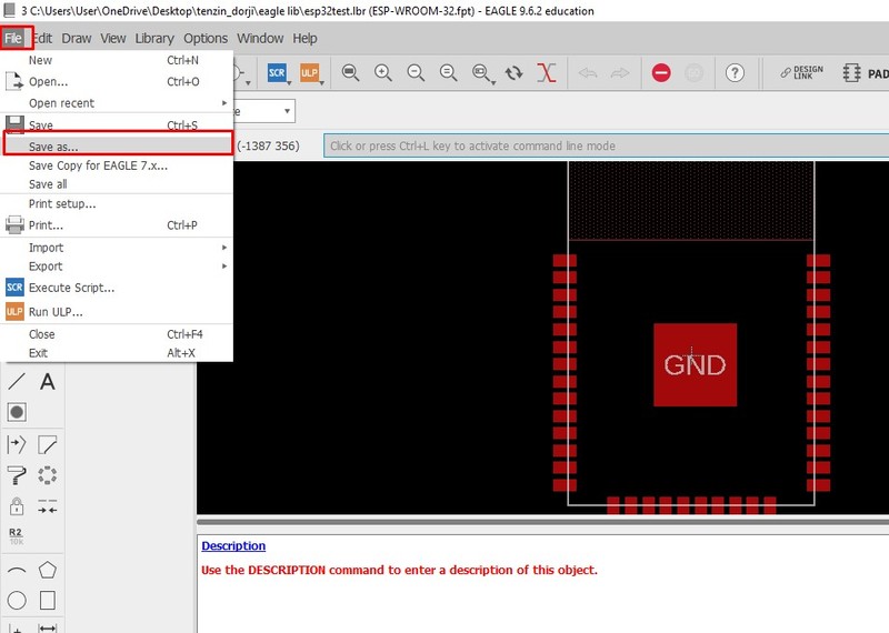
After the change, we need to save it as new library file.
Now open the component (ESP32) from new saved library and check if it worked.
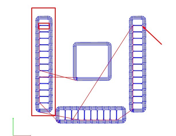
Before I use it in my design, I checked it in MIT MODS and looked working.
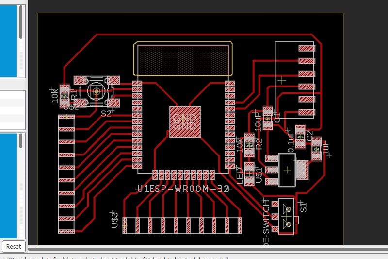
So, I changed the IC from new library that I have saved. Find my trace file and cut files at the end of the assignment.
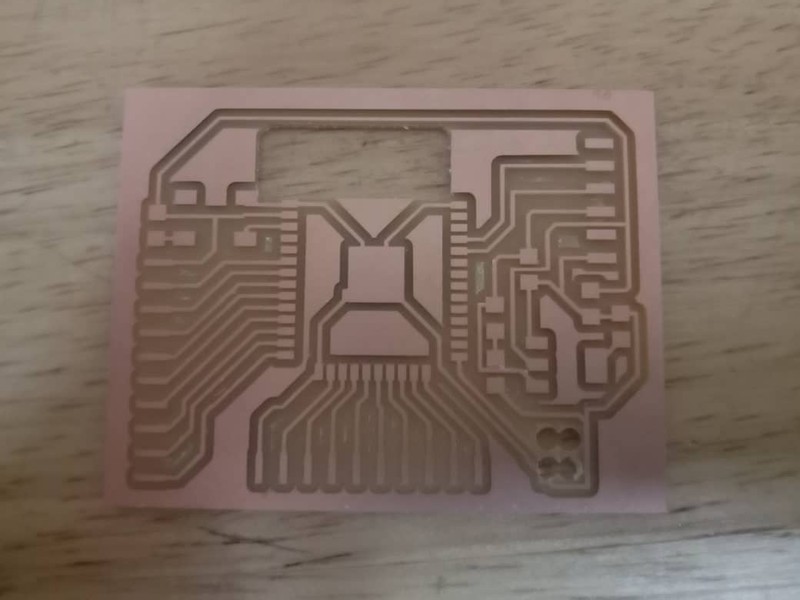
After editing, I did milling again and this time it came out well.
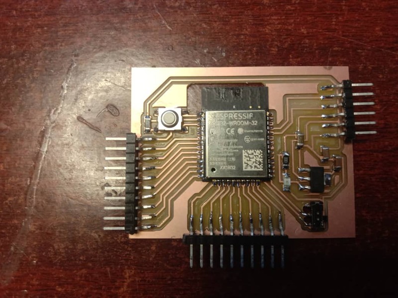
I soldered the required components as per my design and my board get ready for programming.
Programming ESP32:
Now it's time to program the controller board. We can use arduino IDE to program esp32, but we need to install the esp library like we did for attiny.
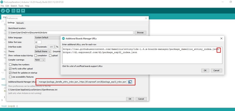
Under Files -> Preferences, we need to paste the https://dl.espressif.com/dl/package_esp32_index.json link as shown in above image. If you have another link already present in the text box, separate it using comma and keeping in new line.
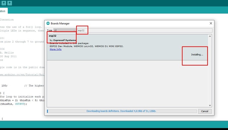
Once added, you can find the library available under Tools -> Board Manager. You can install it.
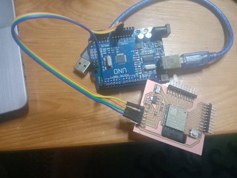
I used arduino as FTDI to program my ESP board. Unlike ATtiny, ESP32 doesn't require programmer, instead it uses FTDI programmer. So, we need to make arduino as FTDI by either
- Shotting the EN and GND of the arduino,
- Removing the IC of the arduino or
- Loading the blank program to the arduino.
I prefered loading program to the arduino to make it as FTDI.
	void setup(){
	pinMode(0,INPUT);
	pinMode(1,INPUT);
	}
	void loop(){
	}
This is simple arduino code that makes RX and TX pin of the arduino as output pin. Load this code to arduino that you are going to use as FTDI.
Now connect ESP board to power supply and connect RX and TX pin of arduino with RXD 0 and TXD 0 pins of ESP32 respectively.
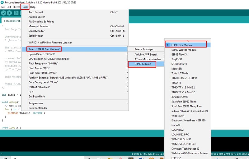
From the Tools -> Boards: -> ESP32 Arduino select ESP32 Dev Module to program our ESP32 WROOM 32 board.
Now keeping the Slide Switch in the programming mode i.e. connected position, to load program. You cannot select the Programmer, now, directly do upload as usual.
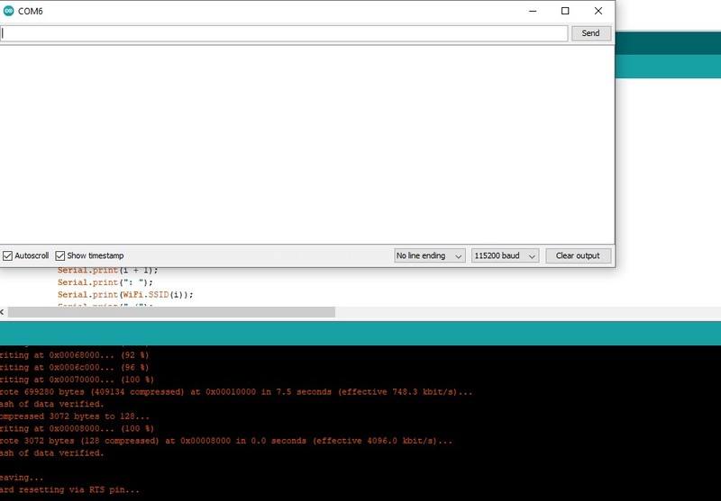
Once uploaded, there will not be any print on the Serial Monitor and it took me a whole lot of time tracing the mistake. But later found out that I need to put back Slide Switch to run position and press the Reset Button once.
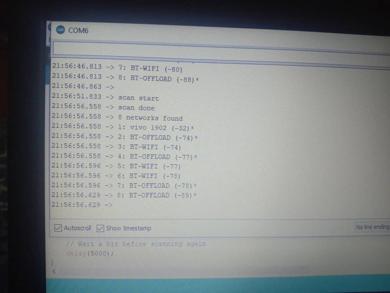
I was trying the example code of WiFiScan.
Programming Ultrasonic Sensor
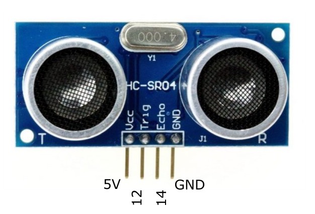
With availability of the GPIO pin of my controller, I selected the pin 12 and 14 for trigger and echo pin respectively for the programming.
My code for ultrasonic sensor as follow:
	#include <ESPmDNS.h>
	#include "WiFi.h"
	#include "ESPAsyncWebServer.h"
	#include <Adafruit_Sensor.h>
	const int trigPin = 12;
	const int echoPin = 14;
	#define SOUND_SPEED 0.034
	long duration;
	float distanceCm;
	const char* ssid = "wifi ssid";
	const char* password = "password";
	AsyncWebServer server(80);
	String readDistance(){
	  digitalWrite(trigPin, HIGH);
	  delayMicroseconds(10);
	  digitalWrite(trigPin, LOW);
	  duration = pulseIn(echoPin, HIGH);
	  distanceCm = duration * SOUND_SPEED/2;
	  Serial.println("Distance:");
	Serial.println(distanceCm);
	   return String(distanceCm);
	}
	const char index_html[] PROGMEM = R"rawliteral(
	<!DOCTYPE HTML><html>
	<head>
	  <meta name="viewport" content="width=device-width, initial-scale=1">
	  <link rel="stylesheet" href="https://use.fontawesome.com/releases/v5.7.2/css/all.css"
	  integrity="sha384-fnmOCqbTlWIlj8LyTjo7mOUStjsKC4pOpQbqyi7RrhN7udi9RwhKkMHpvLbHG9Sr"
	  crossorigin="anonymous">
	  <style>
	    html {
	     font-family: Arial;
	     display: inline-block;
	     margin: 0px auto;
	     text-align: center;
	    }
	    h2 { font-size: 3.0rem; }
	    p { font-size: 3.0rem; }
	    .units { font-size: 1.2rem; }
	    .dht-labels{
	      font-size: 1.5rem;
	      vertical-align:middle;
	      padding-bottom: 15px;
	    }
	  </style>
	</head>
	<body>
	  <h2>Ultrasonic sensor reading on server</h2>
	  <p>
	    <span class="dht-labels">Distance</span>
	    <span id="Distance">%DISTANCE%</span>
	    <sup class="units">Cm</sup>
	  </p>
	</body>
	<script>
	setInterval(function ( ) {
	  var xhttp = new XMLHttpRequest();
	  xhttp.onreadystatechange = function() {
	    if (this.readyState == 4 && this.status == 200) {
	      document.getElementById("Distance").innerHTML = this.responseText;
	    }
	  };
	  xhttp.open("GET", "/distanceCm", true);
	  xhttp.send();
	}, 1000 ) ;
	</script>
	</html>)rawliteral";
	String processor(const String& var){
	  //Serial.println(var);
	   if(var =="DISTANCE"){
	   return readDistance();
	  }
	  return String();
	}
	void setup(){
	  // Serial port for debugging purposes
	  Serial.begin(115200);
	  pinMode(trigPin, OUTPUT); // Sets the trigPin as an Output
	  pinMode(echoPin, INPUT);
	  // Connect to Wi-Fi
	  WiFi.begin(ssid, password);
	  while (WiFi.status() != WL_CONNECTED) {
	    delay(1000);
	    Serial.println("Connecting to WiFi..");
	  }
	  Serial.println("connected to wifi ....");
	  if(!MDNS.begin("ESP32_1234")) {
	     Serial.println("Error starting mDNS");
	     return;
	}
	  Serial.println(WiFi.localIP());

	  // Route for root / web page
	  server.on("/", HTTP_GET, [](AsyncWebServerRequest *request){
	    request->send_P(200, "text/html", index_html, processor);
	  });
	   server.on("/distanceCm", HTTP_GET, [](AsyncWebServerRequest *request){
	    request->send_P(200, "text/plain", readDistance().c_str());
	  });
	  // Start server
	  server.begin();
	  int nrOfServices = MDNS.queryService("http", "tcp");

	  if (nrOfServices == 0) {
	      Serial.println("No services were found.");
	  }
	  for (int i = 0; i < nrOfServices; i=i+1) {
	        Serial.println("---------------");

	        Serial.print("Hostname: ");
	        Serial.println(MDNS.hostname(i));
	        Serial.print("IP address: ");
	        Serial.println(MDNS.IP(i));
	        Serial.print("Port: ");
	        Serial.println(MDNS.port(i));
	        Serial.println("---------------");
	  }
	      Serial.println(ssid);
	    Serial.print("IP address: ");
	    Serial.println(WiFi.localIP());
	    Serial.print("Subnet Mask: ");
	    Serial.println(WiFi.subnetMask());
	    Serial.print("Gateway IP: ");
	    Serial.println(WiFi.gatewayIP());
	    Serial.print("DNS 1: ");
	    Serial.println(WiFi.dnsIP(0));
	    Serial.print("DNS 2: ");
	    Serial.println(WiFi.dnsIP(1));
	    Serial.print("Hostname: ");
	    Serial.println(WiFi.getHostname());
	}
	void loop(){
	}
This is the code I use for my ultrasonic sensor with esp32. I also wanted to display my sensor output on the web, so I get the code from Youtube. I required few edit in order to show my hostname as I couldn't get the local hostname on web with the one written in the code.
Issues faced and solution.
Major issues were faced during the programming of esp with ultrasonic sensor for web.
Issue 1 - code debugging:
As the code requires ESPAsyncWebServer.h library for arduino, I loaded the library as usual downloading from the net.
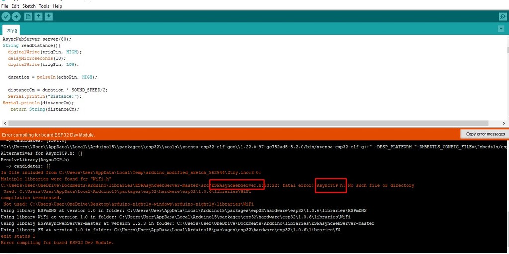
But when I compile, there give the fatal error saying that AsyncTCP.h file is missing. With the help of external expert I found out that I need to add the file externally.
I got the file from Gitlab. I need to download it and add into the library both the .h and .cpp files under ESPAsyncWebServer.h library. After adding the two files, it worked well.
Issue 2 - Web connecting using HostName:
Actually with the given hostname from MDNS, we should be able to access the web with given hostname. But it wasn't working as expected.
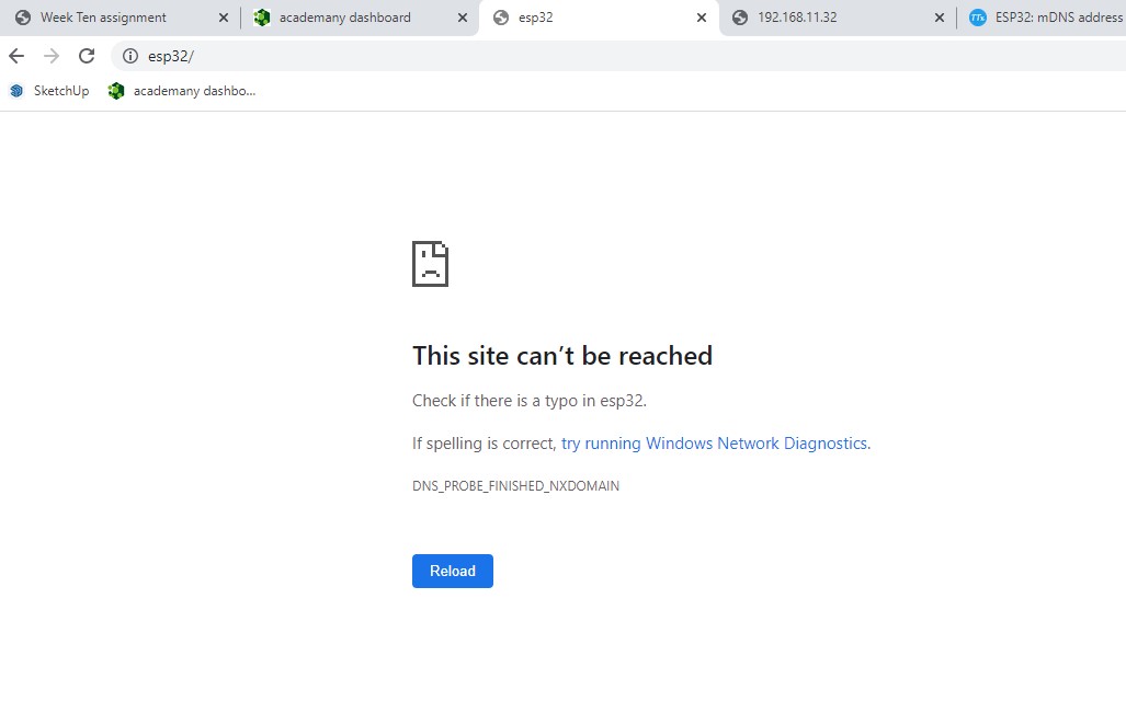
Though it doesn't work with the hostname, it was working well with IP Address allocated. So, we tried to find out the hostname allocated to the ip address by adding some code, which will serial print in the monitor.
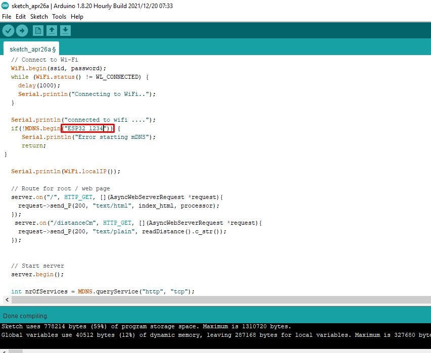
Host name allocated as ESP32_1234 in the code.
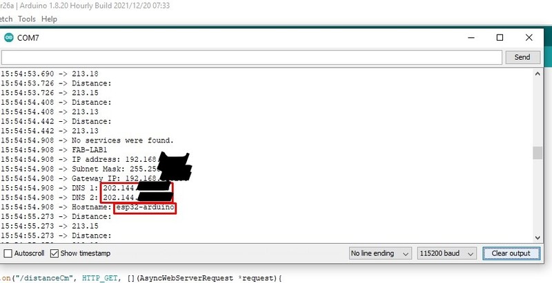
HostName showing as esp32-arduino in hte serial printer.
From the output we also learn that DNS is searching for global ip as 202.148.***.*** instead of local ip as 192.168.**.**. We required to change that but we couldn't resolve after long try.
Instead we resolve temporarily with adding hostname to local ip in the driver. To do that, we need to open notepad as administration and open host file in the system driver from C:\Windows\System32\drivers\etc.
Since my local ip is 192.168.**.**, I added 192.168.**.** ESP32_1234 at the end. This allocate HostName as ESP32_1234 to local ip 192.168.**.**.
This is not really a solution as we force the hostname to the ip address. The real solution will be letting DNS to look for local ip instead of global ip.
- Assignment Files
- ESP32 trace file Here
- ESP32 outline file Here
- ESP32 board & Schemeatic file Find here
- esp32 code from original source.
- esp32 code Here
Reference
- ESP32 Library for eagle: https://github.com/lpodkalicki/eagle-libraries/blob/master/ics/esp32.lbr
- ESP32 tutorial resources: https://randomnerdtutorials.com/
- ESP32 Datasheet: https://www.alldatasheet.com/datasheet-pdf/pdf/1179101/ESPRESSIF/ESP-WROOM-32.html
- Ultrasonic Esp tutorial https://www.youtube.com/watch?v=BxKRJit7I1Y&t=138s
- AsyncTCP master https://github.com/me-no-dev/AsyncTCP/tree/master/src
