Week 11: Mechanical Design, Machine Design
Machine making assignment is the group work assignment. In group we need to make one machine which can be operated and do some specific function.
After discussing in the group and looking for components available, we decided to make PCB Milling machine.
Instruction:
Group Assignment:
- design a machine that includes mechanism+actuation+automation+application
- build the mechanical parts and operate it manually
- document the group project and your individual contribution
Group assignment Here
Individual Assignment:
- Document the group project and your individual contribution
- Group and Work Distribution
- Kamal Kumar Chapagai - Electronics and Programming
- Tenzin Dorji - Electronics and Programming
- Sonam Deki - IT, programming and Documentation
- Pema Yangzom - General for CAD Designing and cutting/printing
- Dorji Tshering Drugyel - General for CAD Designing and cutting/printing
- Thinlet Namgyal - General for CAD Designing and cutting/printing
- Sangay Penjor - Architect for 3D designing and cutting/printing.
Our group consists of six members making group A out of eleven students attending Fab-Academy this year from Fablab Mandala. Following is the names and individual works we distributed after discussing:
Components and Controller:
Kamal sir and I are assigned for Electronics and Programming part as we have electronic background. So, first thing was we needed to find the components and specification for the required electrical parts.
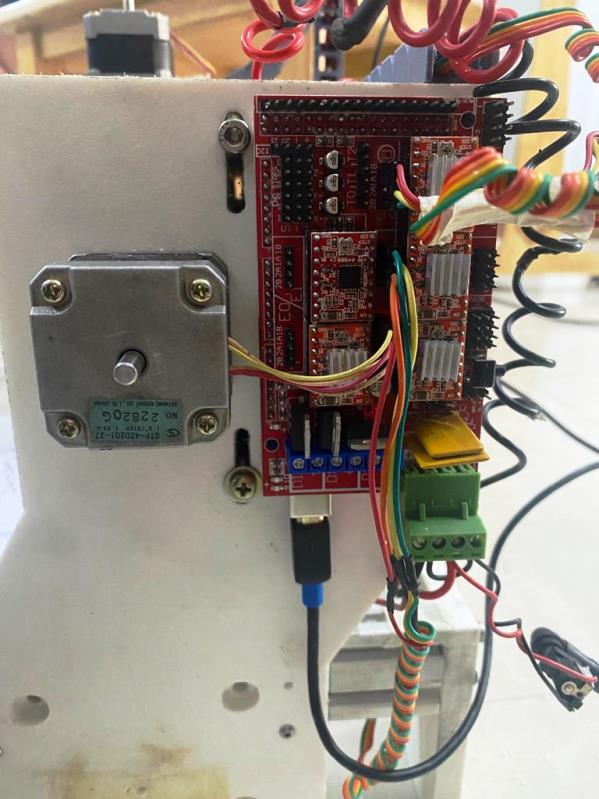
Controller Board and Sheild:
For the controller we got arduino mega with ramps 1.4 sheild for motor driving and controlling.
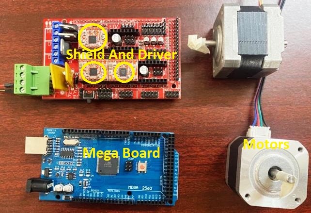
The Arduino Mega board along with its shield and driver connection is shown below:
- Motor and Motor Driver A4988:
- Operating Voltage: 12Volts
- Peak Current : 1.7A / Phase (Two Phase exciting)
- Mass : 0.27kg
- Position Accuracy: 1.8degree per with error range of 5% in full step
- Holding torque: 0.314N-m (3.2kgf-cm) minimum
- Maximum Starting Pulse Rate: 1600pps min, Half-step No-Load
For the controlling of XYZ, we got the stepper motors of STP-42D201-37 specification. Detail specification of the stepper motors are as follow:
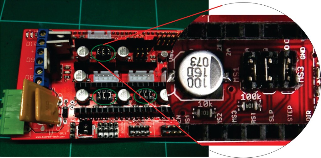
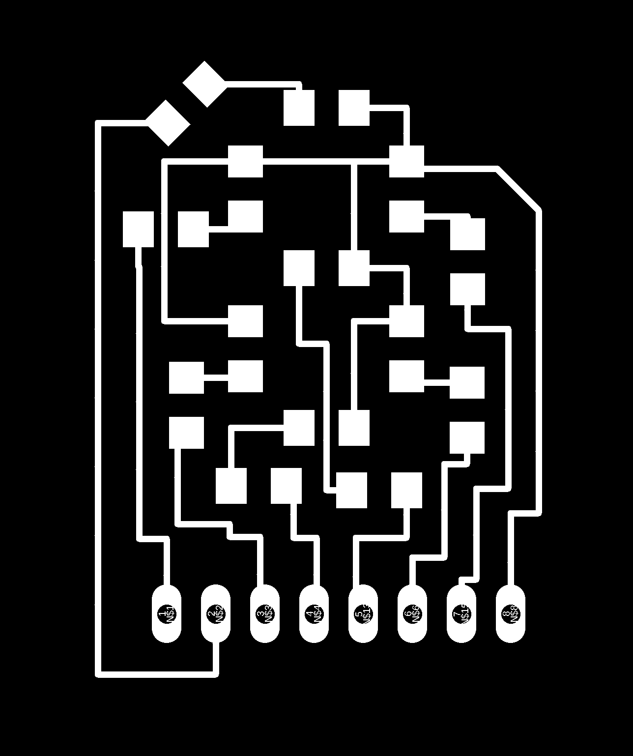
For the motor driving, we are making use of motor driver module with driver A4988. The schematic of the driver is shown below.
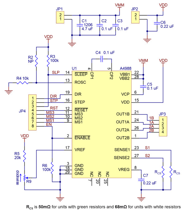
The diver module has the capability of controlling the stepper motor with a maximum current of 2A with additional heat sink requirement while a normal current of 1A can be suppied without overheating.
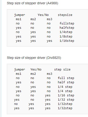
We can set the step size of the stepper to our desire through the selection of following selector pins on RAMPS. Details of steps are as follow:
Firmware and Code
For the milling machine to operate, we need to install the firmware code to the arduino mega. There are many open source firmware and few we used for this project are Merlin and GRBL firmware.
Merlin Firmware:
First created in 2011 for RepRap and Ultimaker by Erik van der Zalm et. al., today Marlin drives most of the world’s 3D printers. Reliable and precise, Marlin delivers outstanding print quality while keeping you in full control of the process. As an Open Source project hosted on Github, Marlin is owned and maintained by the maker community (Source: https://marlinfw.org/).
The marlin firmware can be used to automate 3D printers and other machines. For our work, we tried to work first with MARLIN firmware in grbl controller to check the functionality of the output devices.
Downloading and Installation of Merlin:
I worked more with GRBL than Merlin, but merlin is one of the firmware mostly used for 3D printer fabrication. Download the Merlin firmware from https://github.com/firepick-delta/Marlin.
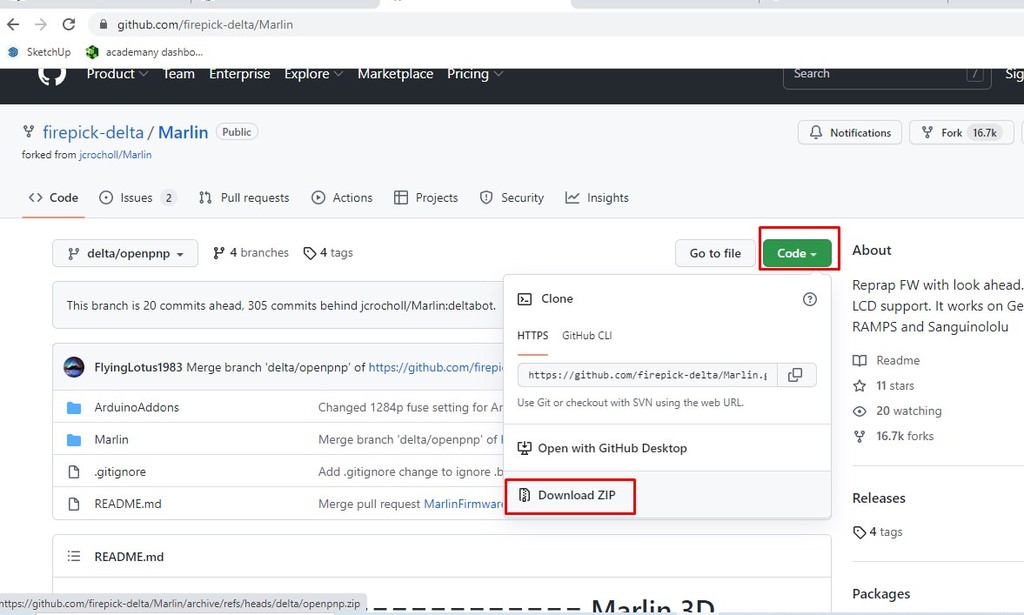
We cannot download merlin firmware like other zip files. The given above link will navigate to a web page like above. From there we need to go to code and from the dropdown we get option to download as zip as shown in above.
After the download, as usual we unzip the file and load in the arduino ide.
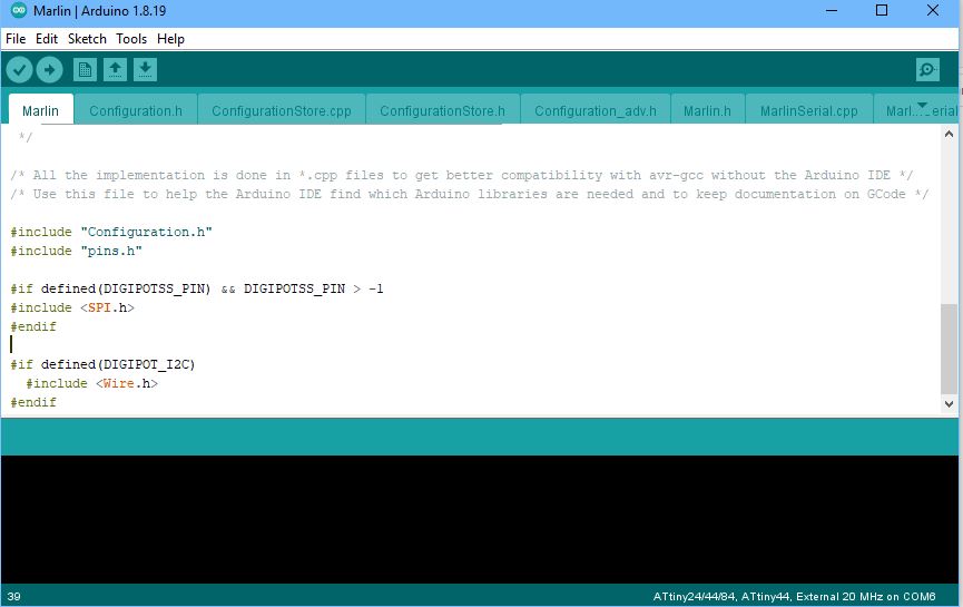
We tried to burn the firmware in the arduino mega, but some unexpected errors kept poping, some were like code sizes. With some research, we came to know that Merlin requires some edit in the (deleting of some code) which is becoming bit burden for us. So, we wanted to give a try with GRBL firmware after the Merlin.
GRBL Firmware:
GRBL is also one of the open source firmware for arduino cnc. Unlike Merlin, GRBL comes in varieties with respect to the board that we are using. We can get the latest release of GRBL from https://github.com/gnea/grbl/releases, but it doesn't work with the arduino mega that we were using.
We had to try with many GRBL of different types for different controllers and lastly we got the compatible one from https://github.com/gnea/grbl-Mega. This firmware is compatible with the arduino mega board but requires some changes in the code as we were using RAMP sheild with mega.
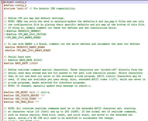
Unlike Merlin, GRBL needs to add as library rather than uploading the whole source code to arduino. Firmware to upload in the arduino just comes with header file and all the source code are in the library.
The first thing that we need to change in the library is about the using of RAMPS. The raw library defines about the usage of Default generic, but as we were using RAMPs 1.4, we need to comment out the defining of DEFAULT_GENERIC and uncomment the defining of DEFAULTS_RAMPS_BOARD.
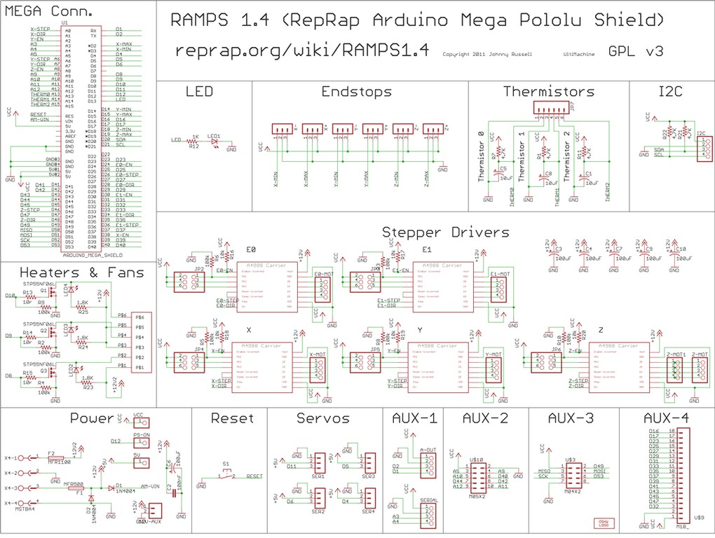
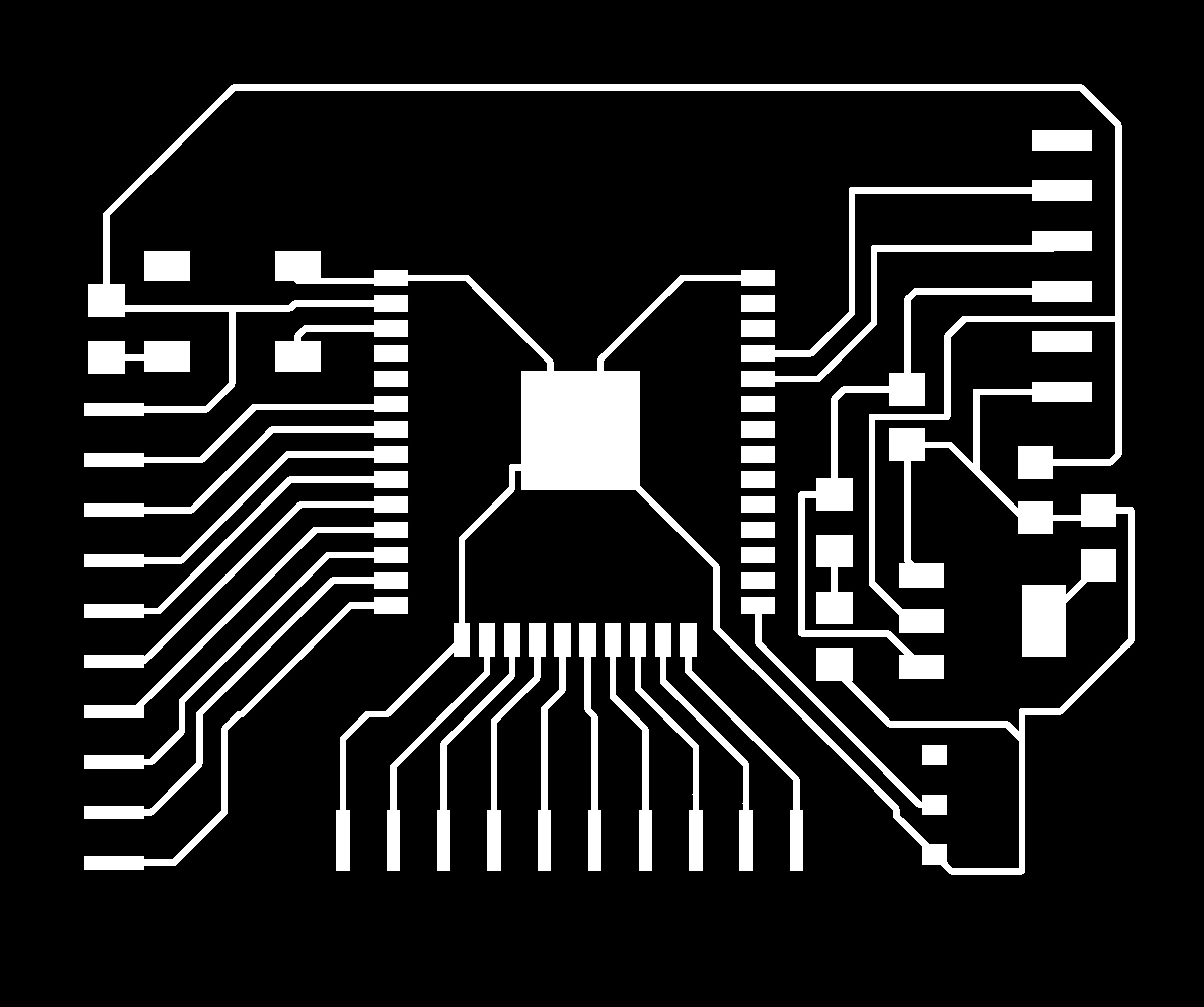
Electrical connections and Software Functionings:
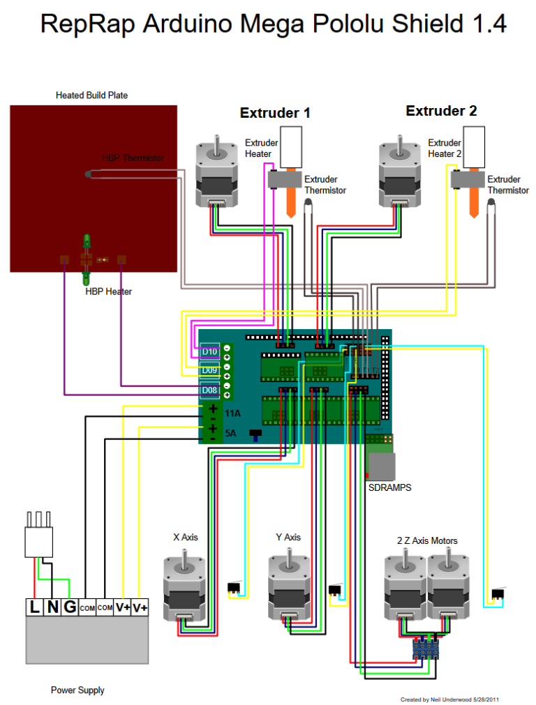
Above diagram is the connection details for the 3D printing application. We do not require all the connections as shown above. We just required X Y and Z axis. X limit, Y limit and Z limit are optional. For the machine fabrication, axes limits are required but for the assignment being, we omitted the limit for now.
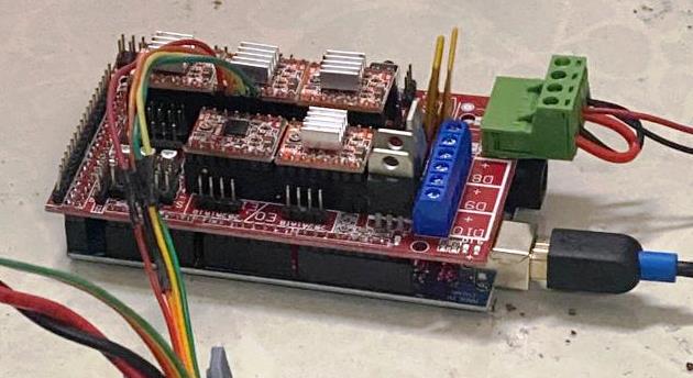
Above is the connection we made for our PCB milling amchine project.
Once the connection is made and Firmware is loaded, we required to use software to run the machine. There are some open source software that can run the firmwares and we used CNCJs software for the project.
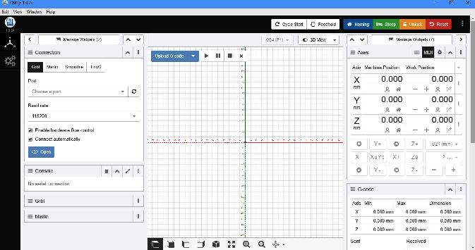
We downloaded CNCjs from https://cnc.js.org/docs/desktop-app/. CNCjs can work with several firmwares like Merlin, GRBL and TinyG.
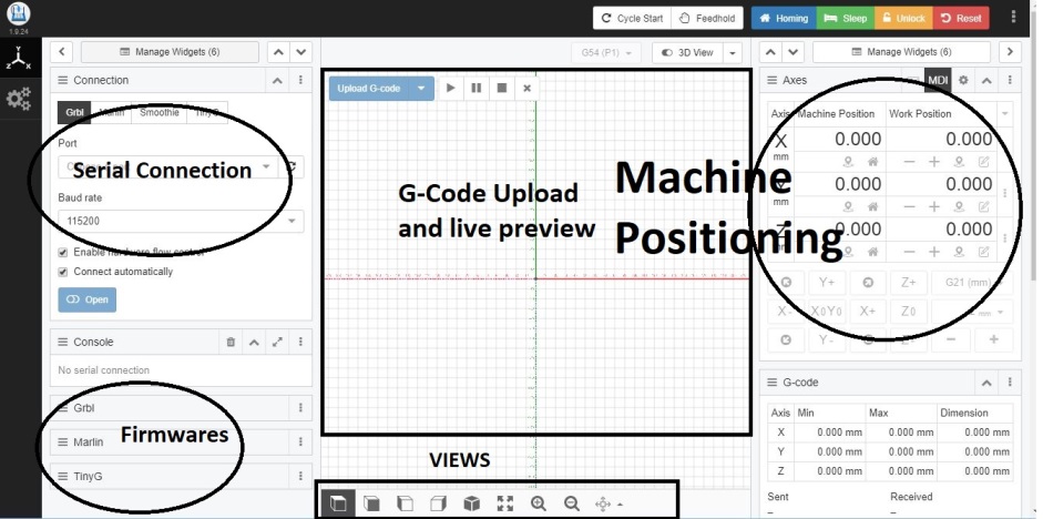
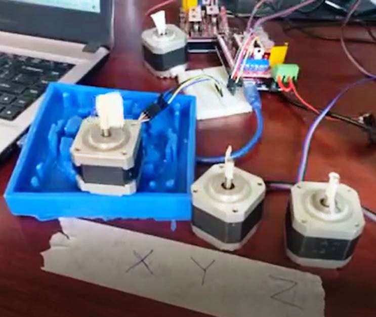
With the GRBL code installed on MEGA board and CNCjs connected to the serial port to the board, we check the functionalities of the XYZ axis motors. The working of the motors is shown in the video below:
Construction and Test Running:
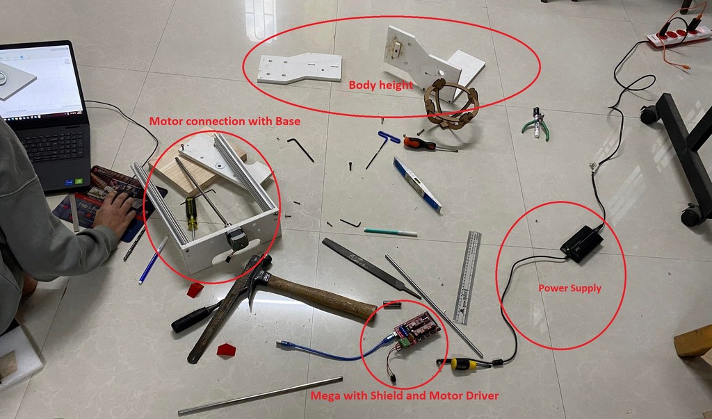
We construct the PCB machine combining the various tasks distributed.
We mount the electrical parts on the body of the machine constructed. Gave the required power supply and tried the test run.
In the test run, we tried to see the bed alignment and running of the machine. Though the running of machine was good, the bed alignment were not satisfactory as shown in above image.
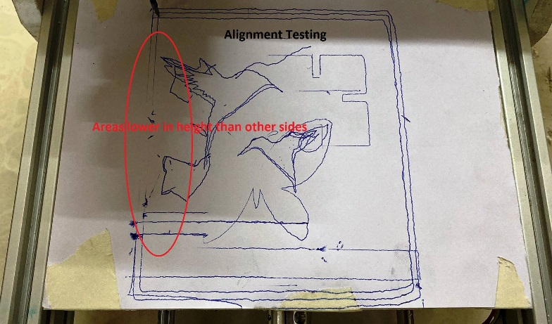
From the side screw slots, we tried to make the alignment as much as we could.
Running after adjusting the alignment
Printing image:
Printing of images and printing of the circuit are similar and if we can successfully sketch something, we are confident enough it will function for its milling. So, we tried to draw some images.
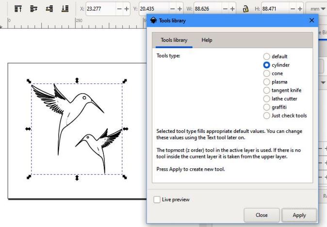
We tried to print the image of bird in above image. As CNCjs requires G-Code for printing, we generate g-code using Inkscape and DXF to G-Code generator.
Detail conversion find on Kamal sir's assignment.
After generating the G-Code, we need to load it to CNCjs software.
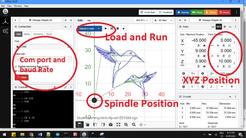
Set the zeroing as shown in above image taking it to the desire position.
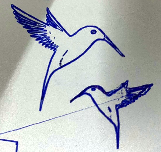
Final outcome we could get after printing.
Watch our working progress and development process of the week.
Reference
- CNCjs: https://cnc.js.org/docs/desktop-app/
- ESP32 tutorial resources: https://randomnerdtutorials.com/
- Merlin Firmware: https://marlinfw.org/
- Arduino Mega GRBL Firmware https://github.com/gnea/grbl-Mega
- Kamal's assignment https://fabacademy.org/2022/labs/bhutan/students/kamalkumar-chapagai/assignments/week11/
