Task to be carried out this week
Action Plan
| Date | Work Allocation |
| 6th April | Prof. Neil's Lecture on Computer Controlled Cutting |
| 7th April | Brain storming and Idea sharing |
| 8th April | Idea conception, initial planning and work distribution |
| 9th April | Reading and research on the building PCB milling machines |
| 10th-11th April | Design and cuttings |
| 12th - 14th April | Assembly of design cutouts |
| 14th - 16th April | Electronicss |
| 17th - 20th April | Machine Assembly, Testing and documentation |
Idea Conception and Planning
The idea came from the problem when milling our PCB on the current PCB milling machine. The bed level on the current Roland- SRM20 machien that we are using had become uneven. DIe to this we faced a number of problem when milling our PCB for output week.
This also caused for the loss of a number of copper plate. Thus, we thought why not try to create a PCB milling machine for this week's machine making week.
Once we all agreed on the idea, the next step was to explore on how to build the machine. Since we do not readily get the electronic components in our country, we had to ensure that all the electronics we required were available in the lab. For this we had to dismantle a couple of previously made machines.
We gathered all the electronics we required and then started with the work. Our group had 7 members, thus we divided the tasks for efficiency. Two people were allocated for designing the components, 3 for electronics and 2 for documenting the entire process.
For the assembly and testing the machine, we all worked together.
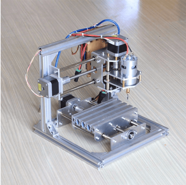
Our plan was to make the machine similar to the one shown in the picture above.
Design and printing the parts
Initially we planned to 3-D print majority of the components but we realsized that the 3-D printer available at out lab was quite small and had the capicity to print only models with maximum of 180mm dimensions. Hence, we cut the bed for the milling machine on the CNC and the body frames using circular saw. For the machine body, we used Alumnium frames and polymer slabs which were cut using circular saw. For the bed, we used wood and cut it using CNC. However, for smaller components such as the cable holders and rod holder we 3D printed them.
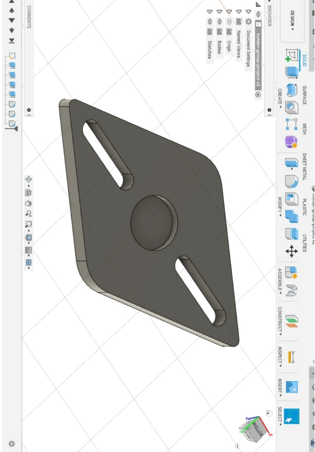

Rod Holders amd cable holders
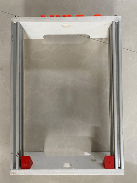
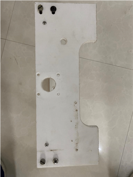
Machine Base and body parts
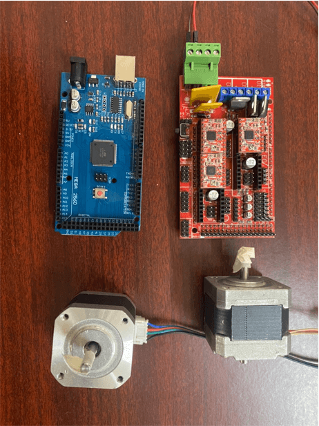
Electronics
For the machine controller, we used Arduino Mega as the microcontroller. Arduino Mega Motor Shield was used to connect the motor driver to the microcontroller. We used 3 moter drivers to control the X,Y and Z axis.

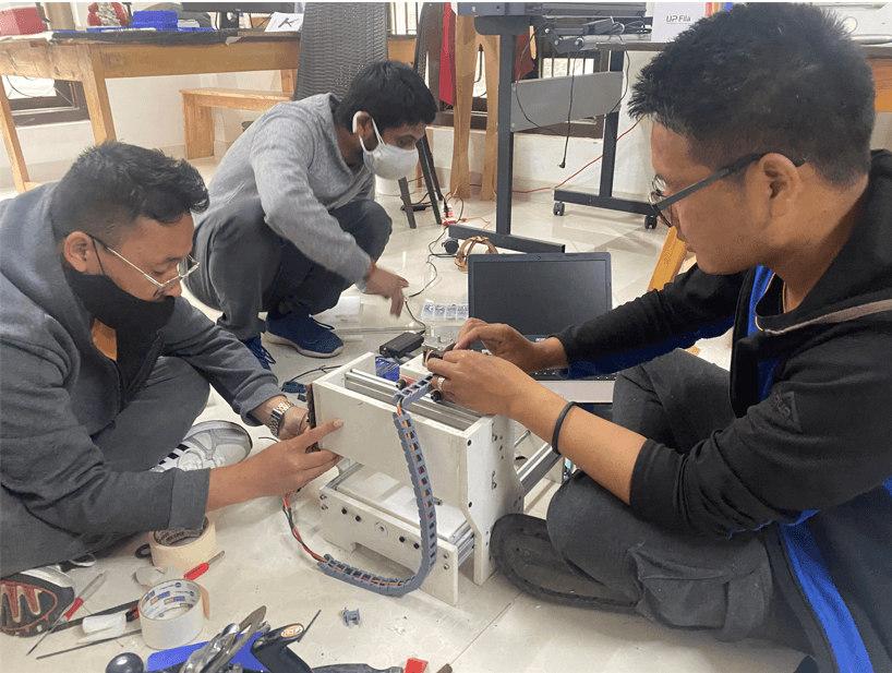
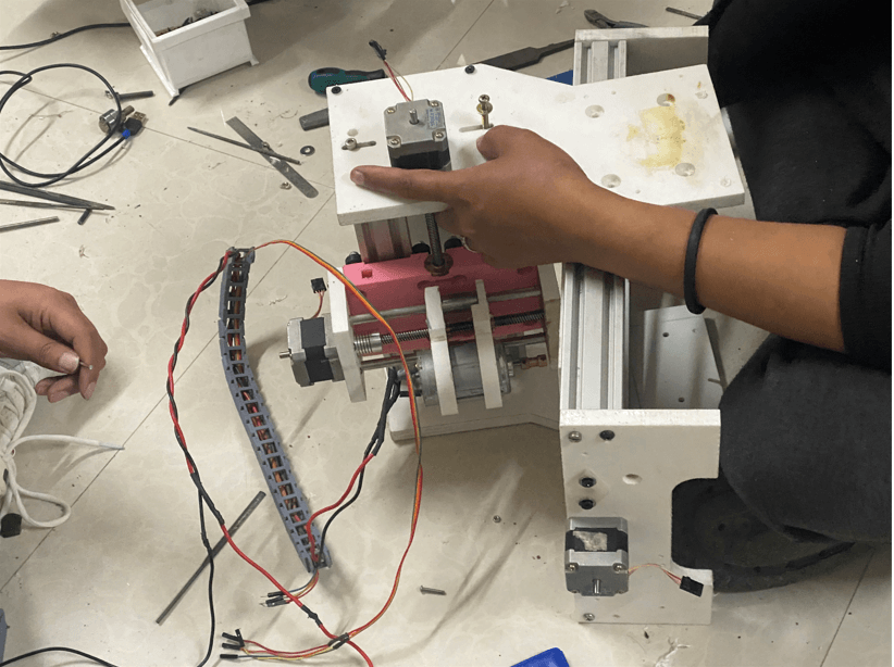
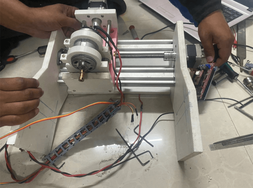
Machine Assembly

Machine Control
For controlling the machine we used G-Code. We downloaded an software called dxf2gcode which converts 2D dxf drawings to CNC machine compatible G-Code.
Testing
Once the machine was assembled, we tested the machine. There were 3 major testing we carried out;
Final Working
