7. Electronics design
This week started with started with the introduction with the components of for a circuit board. I designed the echo Hello World Board. Where the Autodesk eagle software is used to design the sircuit and the PCB layout of the board. From which the png traces were gernetated and the mit mods was used to generate the rml file. So the final goal is to fabricate the board and program it using the USBTiny Programmer.
Task: Electronics Design
- Group assignment:
Use the test equipment in your lab to observe the operation of a microcontroller circuit board (in minimum, check operating voltage on the board with multimeter or voltmeter and use oscilloscope to check noise of operating voltage and interpret a data signal) Document your work to the group work page and reflect on your individual page what you learned
- Individual assignment:
Redraw one of the echo hello-world boards or something equivalent, add (at least) a button and LED (with current-limiting resistor) or equivalent input and output, check the design rules, make it, test it. Optionally, simulate its operation.
Components.
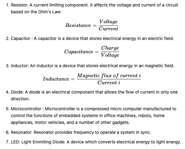
All the components used to developed the Hello World board are mentioned below.
Eagle.
EAGLE is a scriptable electronic design automation application with schematic capture, printed circuit board layout, auto-router and computer-aided manufacturing features. EAGLE stands for Easily Applicable Graphical Layout Editor and is developed by CadSoft Computer GmbH. From Wikipedia
Since EAGLE was already install on my PC, I went through the basics features available in the software.
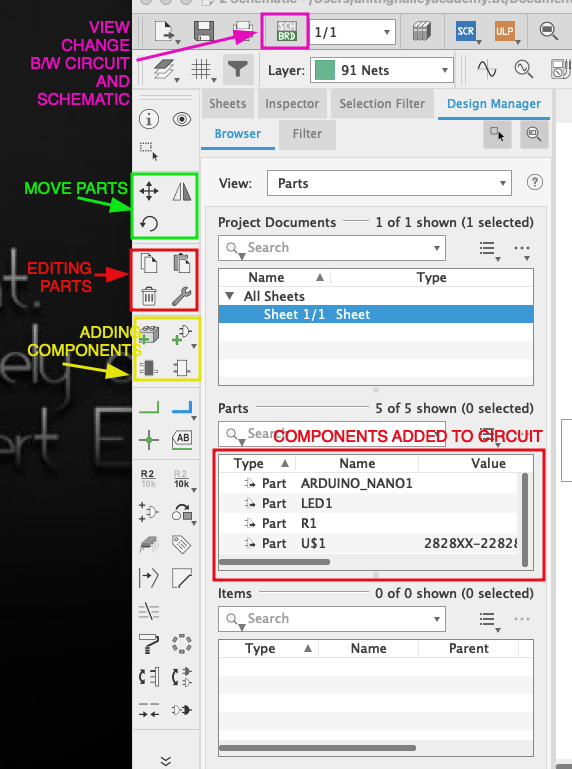
So, next all the components were added to sheet and wire connections are made to connect the circuit and make it ready for designing the traces of the PCB.
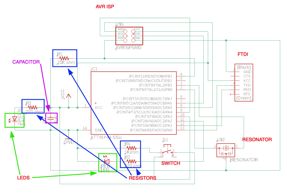
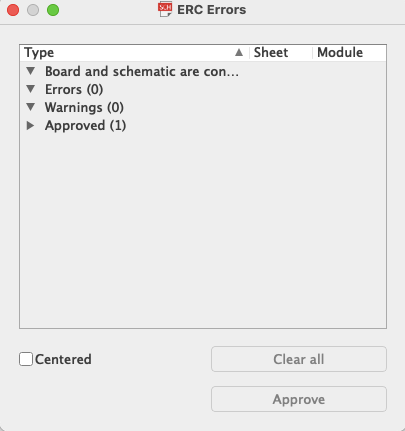
And the Electrical rule checker is raned to do the necessary editing.
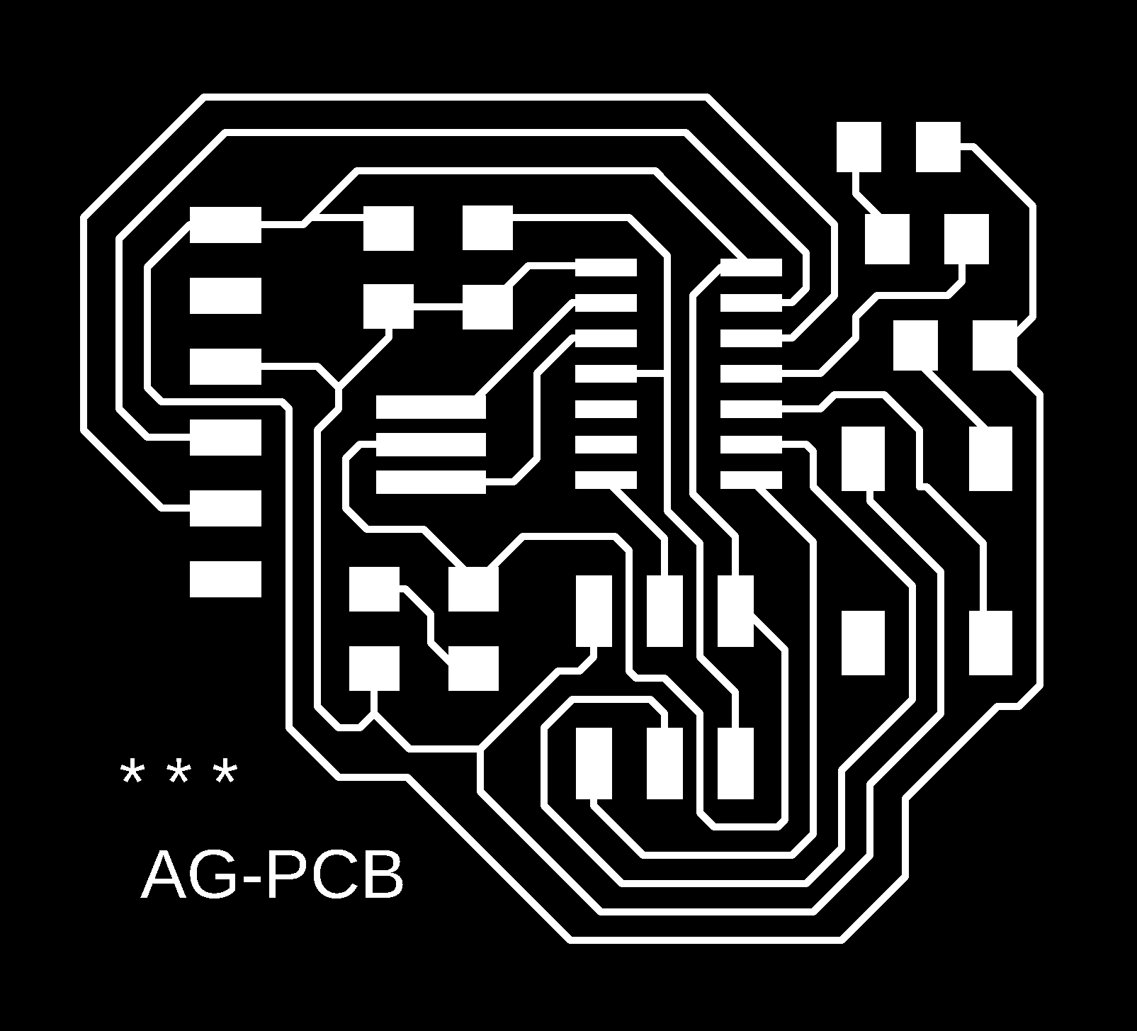
The next work is to creat the routes to be printed on the PCB board. A proper thickness of the route is selected. I felt that most important part in routing the traces is the placement of the components so that it will it will have less criss-cross of connections.
Finally when the routing is completed, we must take not to keep proper spacing between the traces, so that there is no short circuit.
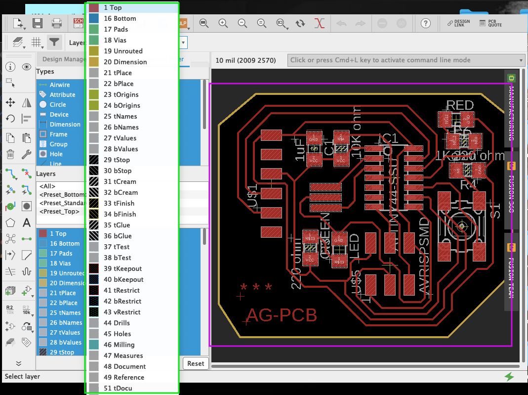
In Eaglw, we can edit the board based on the layers as shown above.
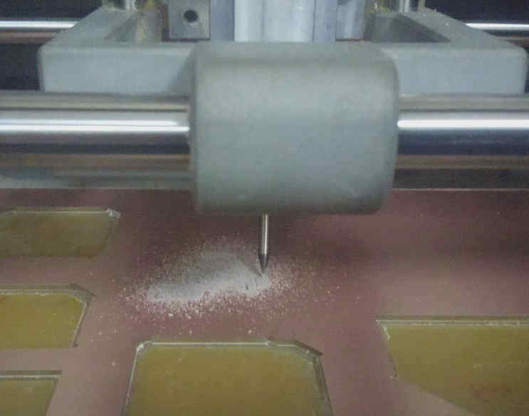
Next to generate the .RML file for the SRM-20 machine, we will generate PNG image for the traces and edge cut Trace.
PNG file for the traces.
PNG file of edge cut.

Using the mit mods, The .rml fil of the traces were generated and provided to the V-panel software.
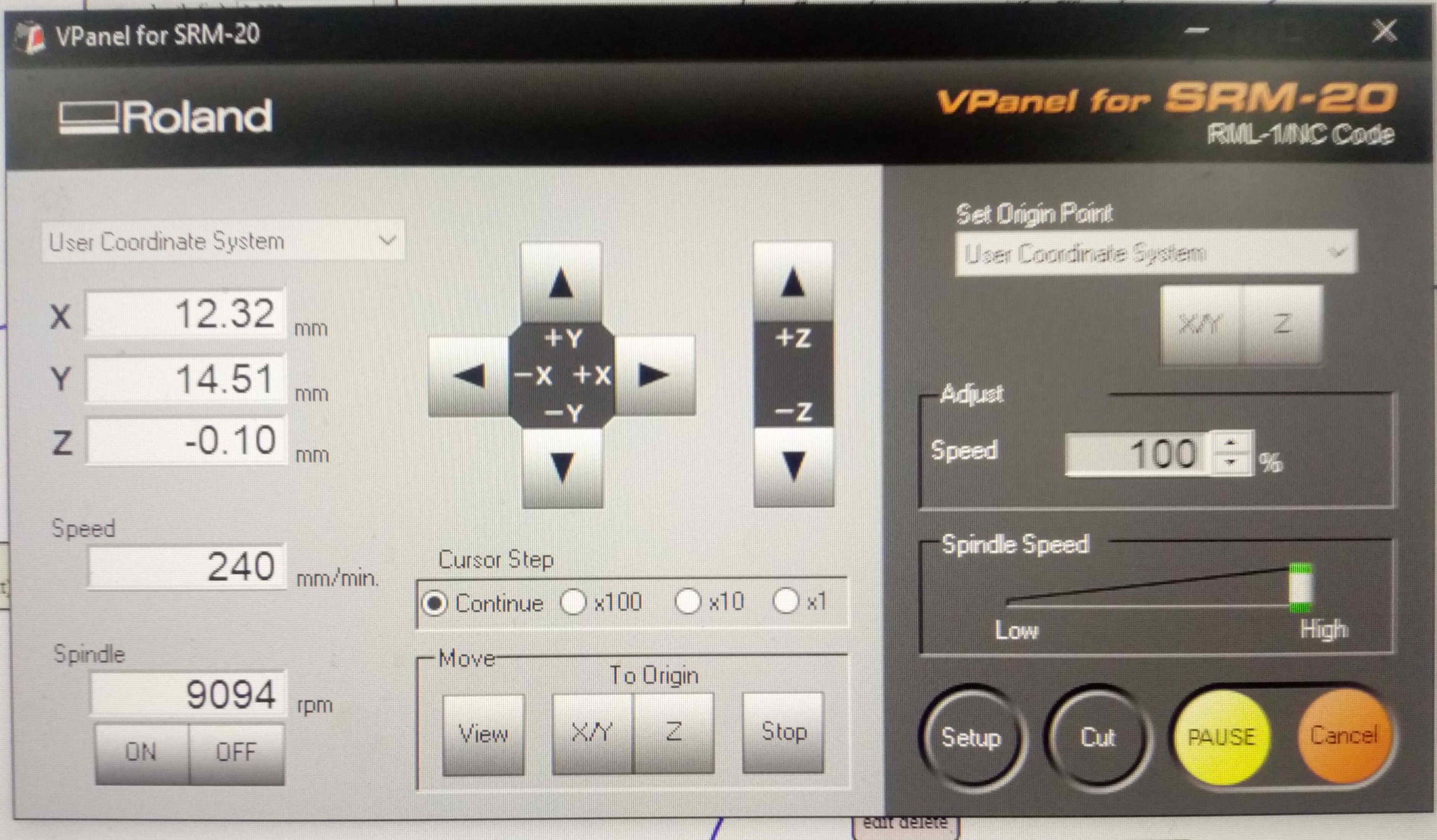
When all the necessary steps were completed and the end mill point is at the right origin, the milling process is started.
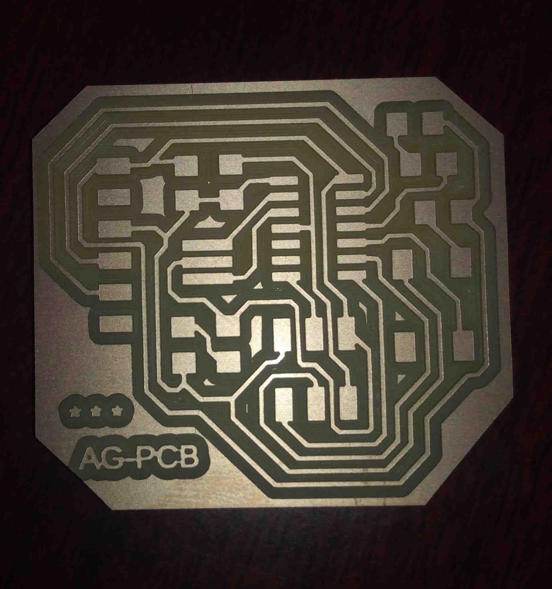
The Printed Circuit Board for the hello world circuit is shown below.
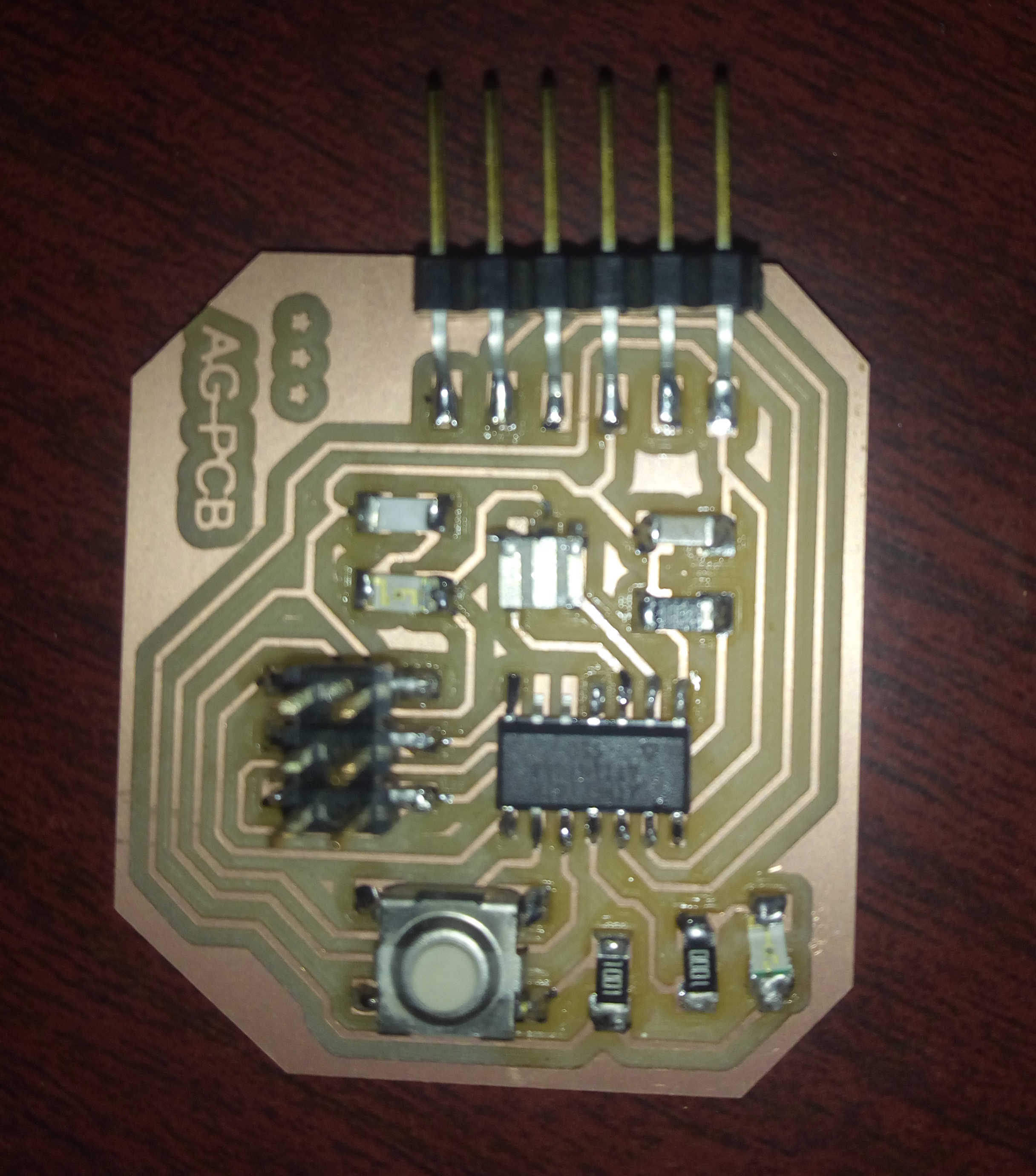
Soldering all the required components.
Now the next step of the work is to solder all the components to the PCB.
The components soldered are:
- LED
- Resistor
- Capacitor
- Resonator
- ATtiny
- Header Pins
- 6x2 AVR ISP
- Switch
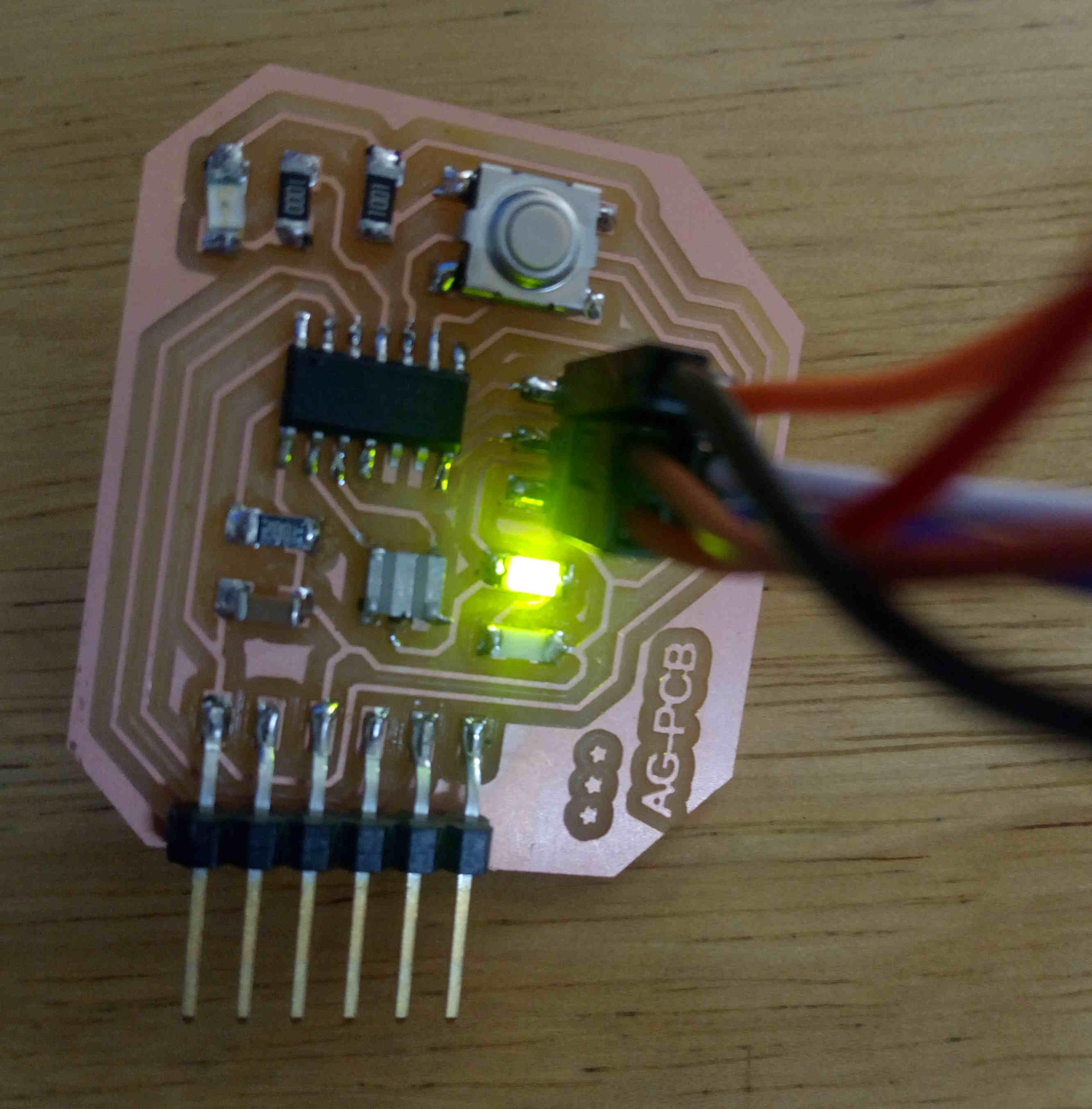
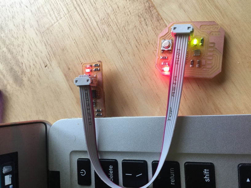
The image below is assembled circuit board with components mounted on it.
Since, due to covid situation in the country, I have the USBTiny fabricated and all the firmwares are updated. Therefore This work was done during the PreFab Academy and during that time Arduino was used to upload the blink Led code on the Hello World Board.
Programming.
To use arduino as the In System Programmer we have to up load the code show below from the example files of Arduino.
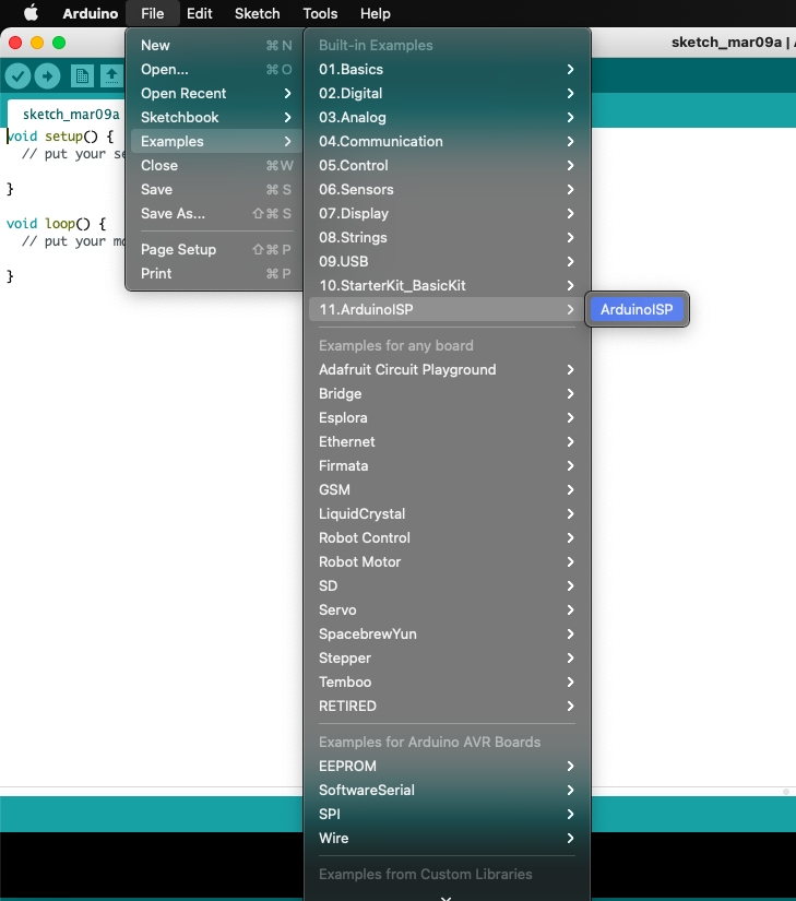
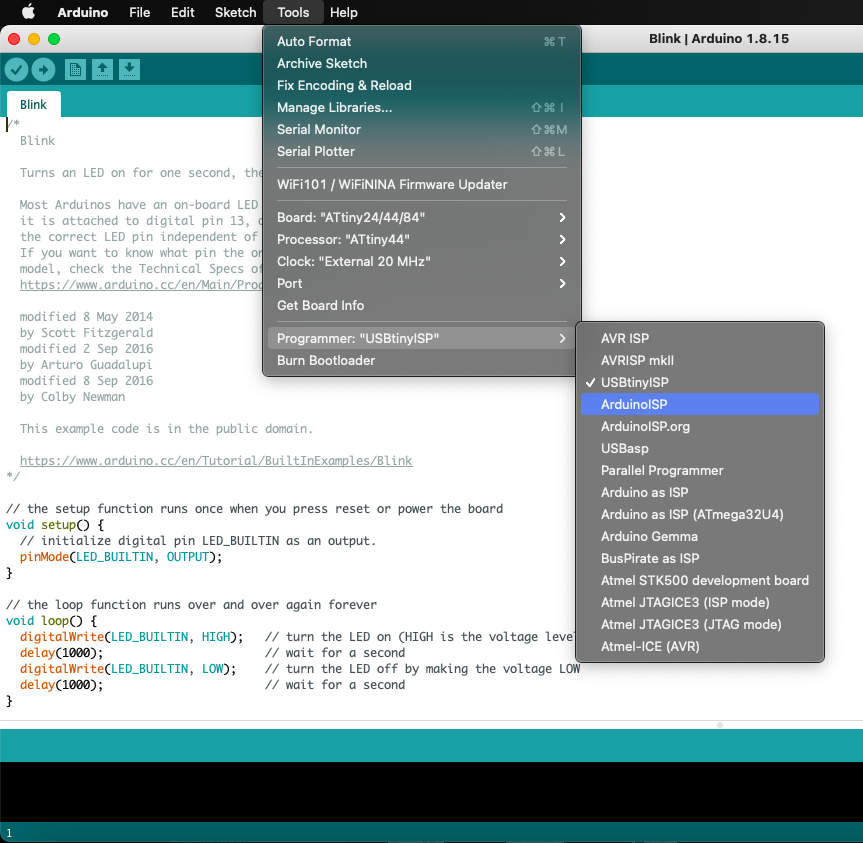
The next job is to upload the blink code on our Hello World Board. 1. Open the blink code from the arduino blink code. 2. Select the Board to ATtiny 22/44/84 3. Select processor as ATtiny 44. 4. Clock as per our resonators specs i.e 20 Mhz. 5. Programmer to. - ArduinoISP, if you are using arduino to program - USBtinyISP, if you are using FabISP (Brian ISP). 6. Before uploading the codes, make sure to burn bootloader.
The image below shows the blinking of the LED when the code is uploaded.
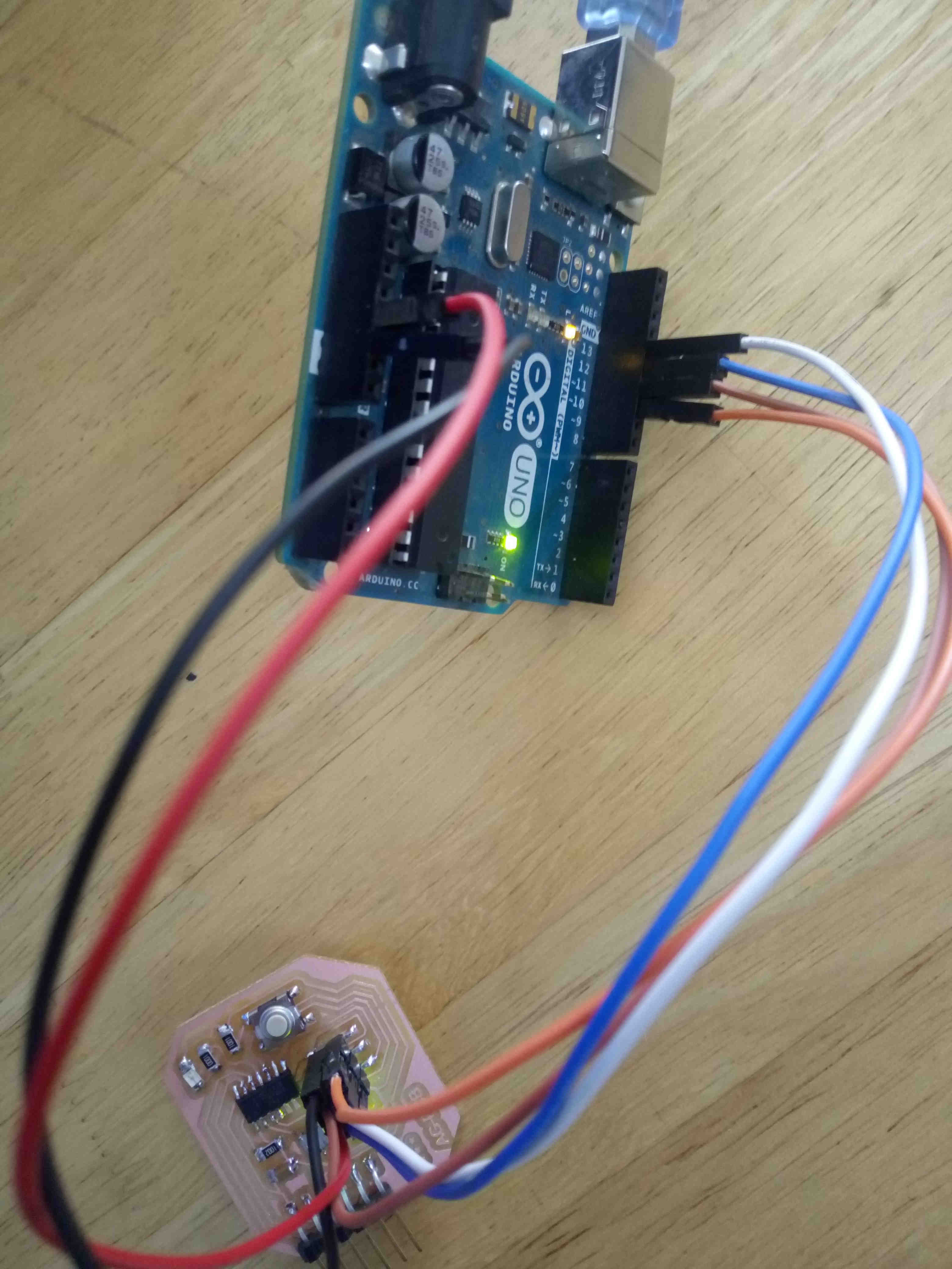
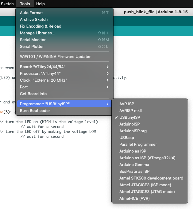
Now the next task is to program the hello world board with fabISP fabricated in the lab. The process is very much similar but we just have to change the programmer to USBtinyISP.
Connect the board with the programmer using the AVRISP cable.
Clip showing the execution of the program on the hello world board.
Review for my work.
From this week assignment, I was able to select my own required components based on the rating. as per ohms law the required value of the resistors was 220 ohm but since this value was not in the inventory, I used the 100 ohm.
But I am happy that I was able to complete the design and fabrication without improvising the board after milling and soldering the board.
Videos
Programming with FabISP.
Programming with Arduino as ISP.
Files
Group Assignment
Digital Oscilloscope
An oscilloscope is used to investigate the health of electronic circuits by analyzing the signals at different points in the circuit. So the most fundamental goal of any oscilloscope is to show you the signals in your circuit.
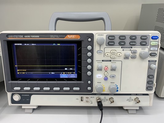
Machine: Digital Oscilloscope- GDS-1202B
Features of oscilloscope
Channels - There are two channels, CH1 and CH2 in the GDS-1202B digital Oscilloscope so we can compare 2 signals at a time.
- Press on CH1 (it will glow to indicate) to show the signal from the probe connected to channel 1 and press on CH2 to show the signal from the probe connected to channel 2 and press on both CH1 and CH2 to compare 2 signals connected from CH1 and CH2.
Horizontal and vertical settings
-
We can change the horizontal and the vertical settings to get proper reading of a signal
-
Horizontal position- Moves the waveform left and right.
-
Vertical position- Moves the waveform up and down.
Scale settings
-
Vertical scale- sets the value of vertical divisions of the graticule in volts/div. Turning this control clockwise makes the waveform appear larger on the display, and vice versa.
-
Horizontal scale- Sets the time scale (seconds/division) and automatically adjusts sampling rate for all waveforms. This makes the waveform appear wider or narrower on the display
Autoset
- Autoset button is used to fit the signal on the scope display.
Run/Stop
- We can click on run/stop button to stop the moving signal so we can study the signal better.
Test channel
-
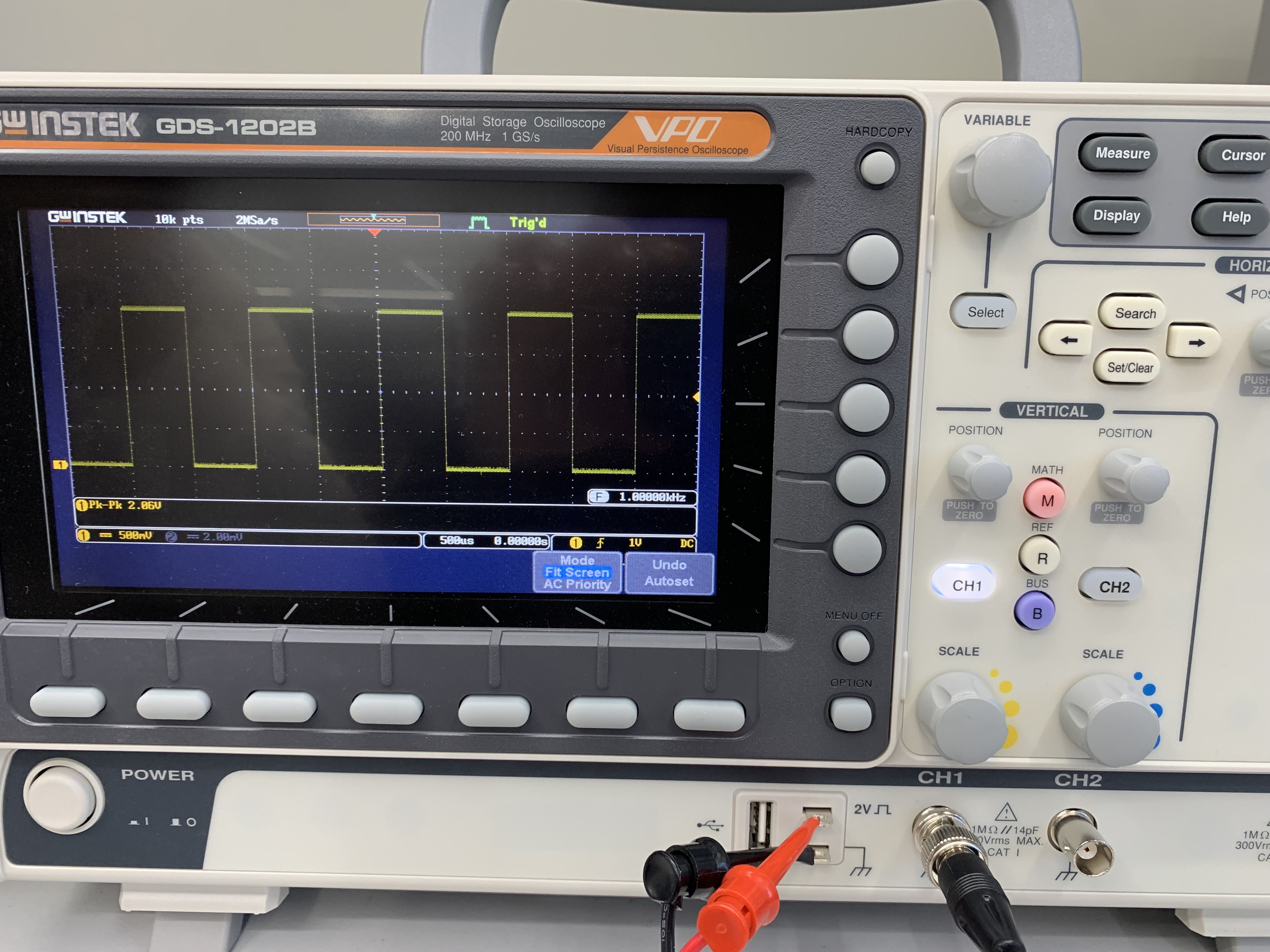
We can test if the oscilloscope is functioning or not by connecting the probes to the 2V square wave and checking the signal on the display
-
Connect the ground lead of the probe to the ground of the oscilloscope and the tip of the probe to the 2V square wave of the oscilloscope.

The display will show a square wave
-
The x-axis represent the volatge.
-
1 unit of x-axis= 500mV
-
The y-axis represent the time.
-
1 unit of y-axis= 500 micro sec
-
The signal signifies that
-
Voltage= 500mV* 4units= 2V
-
Time= 500 micro secs* 2= 1000 micro secs
Calibration
Calibration is the process of configuring an instrument to provide a result for a sample within an acceptable range. So ensure to calibrate your oscilloscope from time to time. We can calibrate the oscilloscope using a screw that is provided along with the oscilloscope.
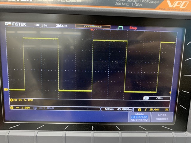
Testing microcontroller on oscilloscope
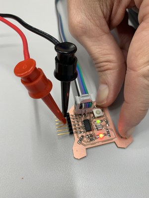
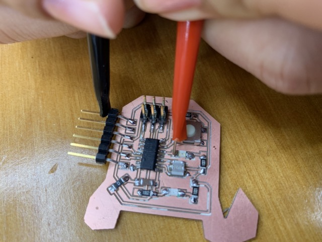
- To test the power signal in the board, I placed the red(positive) probe to the VCC pin in the male connector and the black (negative) probe to the GND in the Male connector
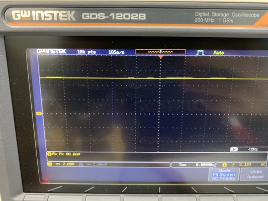
X-axis shows the voltage and the y-axis shows the time
- x-axis 1unit= 2V
- y-axis 1unit= 5 ns
- To test the signal that the green LED is receiving from the ATTINY 44 microcontroller, I placed the red(positive) probe to the positive of the Green LED. and the black (negative) probe to the GND.
Since the board to programed to blink, the volatge changes from 0V to 5V and then back to 0V with delay of 1000 ms
X-axis shows the voltage and the y-axis shows the time
- x-axis 1unit= 1V
- y-axis 1unit= 500ms